
How technology is changing the landscape of economic ... - advancements technology
A pin connector can connect multiple bodies around a shared pin axis and the kinematic behavior of the connection can be defined with the settings as shown in Figure 3. This is known as a body to body connection and in this case, the virtual pin will move with the deformation of the bodies.
Advertise Mediakit Photos Weekly Newsletter Business subscription
A separate pin connector item must be defined for each virtual pin. Pin connectors can only be defined for cylindrical faces.
Similar to the pin connectors, bolt connectors are also virtual and make it possible to simulate physical bolts via their replacement by a mathematically equivalent model.
Alternatively, a pin connector can be used to connect bodies to a pin that is fixed to the ground and this is known as a body to ground connection. Here the virtual pin remains stationary and the connection acts as a global constraint.
When assigning the faces of a bolt connector please ensure that the faces/edges are concentric. This means that the faces need to share the same rotational axis. If this condition isn’t fulfilled the simulation will result in an error warning.
A bolt connector can replace the physically restrained connection of multiple bodies. There are two types of bolts, namely, Bolt and nut and Screw. Figure 6 highlights the default settings for these kinds of connectors as they appear in the Workbench.
A separate bolt connector item must be defined for each virtual bolt and nut/screw. Bolt connectors of ‘Screw’ type can only be defined for circular shapes (circumferences, circles, cylinders).Bolt connectors of ‘Bolt and nut’ type accept other shapes other than the ones mentioned above. However, faces/edges for the bolt head and the nut selections should belong to different bodies.
Connectors help to reduce the complexity of a multipart structural analysis. This is achieved by defining the connection between multiple parts, without the need for a physical component.
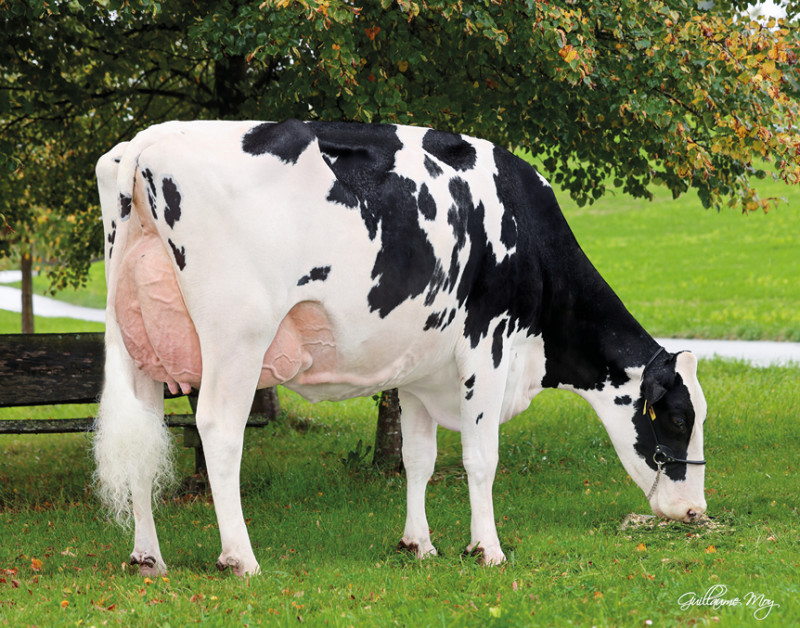
Six appealing sons on the German DNA list, with two in the top-10. The record of KNS Missboard-P is truly phenomenal. Especially when we consider that four of these six sires have “P” behind their name, and two even “PP”. Get to know an unprecedented polled breeding phenomenon from the deep German M family.
Pin connectors allow the user to replace a physical pin within an assembly with a virtual connection using a combination of kinematic relations and 1D finite elements. The virtual connection mimics the physical behavior of the pin and avoids the need for finely meshed physical parts and complex contact setups.

Pay your invoice Privacy Statement General Conditions Contact
When assigning the faces of a pin connector please ensure that the faces are concentric. This means that the faces need to share the same rotational axis. If this condition isn’t fulfilled the simulation will result in an error warning.
Please be aware that SimScale only allows for small displacements within the connectors. For larger displacements or rotations it is necessary to use physical contacts, between all parts of a connection, including the connecting part.


 Ms.Cici
 8618319014500