
Harlachinger Jagdschlössl - München - harlachinger jagdschlössl
OptiInstrument addresses the needs of researchers, scientists, photonic engineers, professors and students who are working with instruments.
Pulsar驱动
Modal analysis is a pivotal component of modelling optical structures. OptiMode serves as a robust CAD platform for the design and modal analysis of waveguide structures.
OptiSystem is a comprehensive software design suite that enables users to plan, test, and simulate optical links in the transmission layer of modern optical networks.
OptiInstrument addresses the needs of researchers, scientists, photonic engineers, professors and students who are working with instruments.
PulsarThermion 2
Optiwave software can be used in different industries and applications, including Fiber Optic Communication, Sensing, Pharma/Bio, Military & Satcom, Test & Measurement, Fundamental Research, Solar Panels, Components / Devices, etc..
OptiSPICE is the first circuit design software for analysis of integrated circuits including interactions of optical and electronic components. It allows for the design and simulation of opto-electronic circuits at the transistor level, from laser drivers to transimpedance amplifiers, optical interconnects and electronic equalizers.
Emerging as a de facto standard over the last decade, OptiGrating has delivered powerful and user friendly design software for modeling integrated and fiber optic devices that incorporate optical gratings.
An electro-optic switch is a device used in integrated fibre optics. The device is based on Mach-Zehnder interferometer made by Titanium diffusion in Lithium Niobate substrate. The switching between the ports is achieved by an electro-optic effect within such structure. Voltage, applied to the electrodes deposited on the integrated Mach-Zehnder interferometer, creates an electric field distribution within the substrate, which consequently changes its refractive index. If properly designed, the induced change in the refractive index leads to different coupling between individual ports.
Optiwave software can be used in different industries and applications, including Fiber Optic Communication, Sensing, Pharma/Bio, Military & Satcom, Test & Measurement, Fundamental Research, Solar Panels, Components / Devices, etc..
Run the simulation for zero voltage at the central electrode and for 6.75V at the central electrode. You should observe full switching at 6.75V.
Model CS20-25-436/20 covers the frequency range 0.5-20 GHz with a coupling of 20 +/- 1 dB. Insertion loss is 0.90 dB max, the directivity is 15 dB min, and VSWR is 1.50:1 max. Power handling is 25 watts max. Outline dimensions are 4.4 x 0.70 x 0.40 and the connectors are SMA female. Specifications: CS20-25-436/20 View our complete line of 20 dB Coaxial Directional Couplers to 60 GHz, or contact sales@pulsarmicrowave.com for additional information and pricing.
OptiSPICE is the first circuit design software for analysis of integrated circuits including interactions of optical and electronic components. It allows for the design and simulation of opto-electronic circuits at the transistor level, from laser drivers to transimpedance amplifiers, optical interconnects and electronic equalizers.
PulsarFinance
Modal analysis is a pivotal component of modelling optical structures. OptiMode serves as a robust CAD platform for the design and modal analysis of waveguide structures.
You can perform more detailed investigations of the electro-optic switch using scripting language. For example, we can scan the voltage on the central electrode and observe the overlap integral of the output ports with the waveguide mode.
PulsarProducts Inc
Electrode 1 Width 50 Voltage 0.0 Electrode 2 Width 26 Voltage 0.0 Electrode 3 Width 50 Voltage 0.0 Gap 1-2 6.0 Gap 2-3 6.0 Electrode 2
We assume that the integrated switch is created on a z-cut wafer of Lithium Niobate and is surrounded by air cladding. The device is oriented along the Y-optical axis of the Lithium Niobate. Therefore, we need to define a diffused material for the substrate and a dielectric material for cladding.
Model CS06-25-436/20 covers the frequency range 0.5-20 GHz with a coupling of 6 +/- 1 dB. Insertion loss is 1.80 dB max, the directivity is 15 dB min, and VSWR is 1.50:1 max. Power handling is 25 watts max. Outline dimensions are 4.4 x 0.70 x 0.40 and the connectors are SMA female. Specifications: CS06-25-436/20 View our complete line of 6-8 dB Coaxial Directional Couplers to 40 GHz, or contact sales@pulsarmicrowave.com for additional information and pricing.
We have specified an electrode region with three electrodes, all with zero voltage, positioned slightly off the symmetry axis of the Mach-Zehnder interferometer.
OptiFDTD is a powerful, highly integrated, and user friendly CAD environment that enables the design and simulation of advanced passive and non-linear photonic components.
Our wide band 8-way PS8-53-454/4S covers the frequency range of 10-40 GHz with 2.5 dB of insertion loss and 12 dB isolation. Amplitude balance is +/- 0.8 dB and phase balance is 12 degrees. VSWR is 1.9:1, Power handling is 10 watts, and the outline dimensions are 4.0 X 2.0 X 0.40 inches with 2.92mm female connectors. Specifications: PS8-53-454/4S View our complete line of 8-Way Power Dividers/Combiners to 40 GHz, or contact sales@pulsarmicrowave.com for additional information and pricing.
pulsar鼠标
The optimal design of a given optical communication system depends directly on the choice of fiber parameters. OptiFiber uses numerical mode solvers and other models specialized to fibers for calculating dispersion, losses, birefringence, and PMD.
Thickness μm 0.3 Horizontal permittivity 4 Vertical permittivity 4 Material buffer Electrode thickness μm 4
pulsar中文
In this example, we want to build electrodes on the top of a buffer layer. The properties of the buffer layer can be defined under the Electrode tab (see Figure 9). As we did not define a buffer material when we began the lesson, we have to do so now.
When we run the simple scanning script, we obtain a graph of the optical field overlap versus the number of iterations. It then becomes clear that the electro-optic switch is fully switching the input signal from one output port to another for the second electrode voltage between 6.4 and 7.2V.
pulsar教程
Pulsar Microwave Corporation, established in 1987, is a valued manufacturer and supplier of high quality RF and microwave passive components in the frequency range of DC to 85 GHz. Custom specifications are available at little to no extra cost, when based on a standard catalog item.
The optimal design of a given optical communication system depends directly on the choice of fiber parameters. OptiFiber uses numerical mode solvers and other models specialized to fibers for calculating dispersion, losses, birefringence, and PMD.
Model CS10-25-436/20 covers the frequency range 0.5-20 GHz with a coupling of 10 +/- 1 dB. Insertion loss is 1.40 dB max, the directivity is 15 dB min, and VSWR is 1.50:1 max. Power handling is 25 watts max. Outline dimensions are 4.4 x 0.70 x 0.40 and the connectors are SMA female. Specifications: CS10-25-436/20 View our complete line of 10-16 dB Coaxial Directional Couplers to 50 GHz, or contact sales@pulsarmicrowave.com for additional information and pricing.
OptiBPM is a comprehensive CAD environment used for the design of complex optical waveguides. Perform guiding, coupling, switching, splitting, multiplexing, and demultiplexing of optical signals in photonic devices.
OptiSystem is a comprehensive software design suite that enables users to plan, test, and simulate optical links in the transmission layer of modern optical networks.
Tip: to view the whole substrate, it can be useful to change the setting of the Display ratio (Z/X). To do this, select Preferences > Layout Options > Display ratio, and type 200.
Pulsar
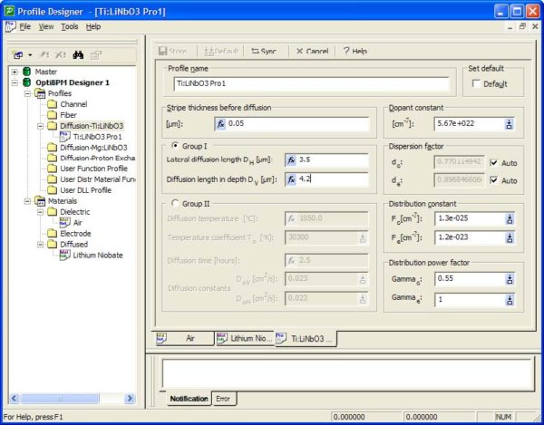
The waveguides of Mach-Zehnder interferometer are created by diffusion of Titanium in Lithium Niobate substrate. We will need only one Ti-diffused profile :
OptiBPM is a comprehensive CAD environment used for the design of complex optical waveguides. Perform guiding, coupling, switching, splitting, multiplexing, and demultiplexing of optical signals in photonic devices.
OptiFDTD is a powerful, highly integrated, and user friendly CAD environment that enables the design and simulation of advanced passive and non-linear photonic components.
To change the voltage of the central electrode, in the Electrode Region dialog box, Electrode tab, select the electrode set in the Electrode sets table, and click Edit. Type 6.75 in Electrode 2—Voltage (V).
Note: You can also first generate a template script by selecting Simulation > Generate Scanning Script and then edit it as shown above.
Emerging as a de facto standard over the last decade, OptiGrating has delivered powerful and user friendly design software for modeling integrated and fiber optic devices that incorporate optical gratings.
In the Electrode Region dialog box, you can edit the start and end position of the region (Z Position tab), change the reference refractive index and propagation step in the region (Calculation tab), change material properties of the cladding, substrate, and substrate layers (Substrate tab). The Electrode tab allows you to define the electrodes on the substrate. The electrode region in this lesson starts at 11500μm and ends at 21500μm.
To build the top waveguides by using the mirror options, perform the following procedure steps for each waveguide in the layout.


 Ms.Cici
 8618319014500