
Giant Light Bright - large light bright
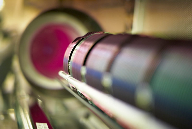
CCDs and CMOS imagers were both invented in the late 1960s and 1970s (DALSA founder Dr. Savvas Chamberlain was a pioneer in developing both technologies). CCD became dominant, primarily because they gave far superior images with the fabrication technology available. CMOS image sensors required more uniformity and smaller features than silicon wafer foundries could deliver at the time. Not until the 1990s did lithography develop to the point that designers could begin making a case for CMOS imagers again. Renewed interest in CMOS was based on expectations of lowered power consumption, camera-on-a-chip integration, and lowered fabrication costs from the reuse of mainstream logic and memory device fabrication. Achieving these benefits in practice while simultaneously delivering high image quality has taken far more time, money, and process adaptation than original projections suggested, but CMOS imagers have joined CCDs as mainstream, mature technology.
CMOS area and line scan imagers outperform CCDs in most visible imaging applications. TDI CCDs, used for high speed, low light level applications, outperform CMOS TDIs. The need to image in the NIR can make CCDs a better choice for some area and line scan applications. To image in the UV, the surface treatment after backside thinning is key, as is the global shutter requirement. The need for very low noise introduces new constraints, with CMOS generally still outperforming CCDs at high readout speeds. The price-performance trade-off can favor either CCD or CMOS imagers, depending on leverage, volume, and supply security.
UV response and backside thinning are achievable in all line scan imagers, but not all area imagers. No global shutter area CCD can be backside thinned. The situation is better in CMOS area imagers, though still not without trade-offs. CMOS area imagers with rolling shutter can be backside thinned. Conventional CMOS global shutter area imagers have storage nodes in each pixel that need to be shielded when thinned, but only if these UV sensitive imagers will also be imaging in the visible. In backside thinned area imagers, it is not possible to effectively shield part of the pixel from incident illumination, without severely degrading the imager’s fill factor (the ratio of the light sensitive area to the total pixel area). There are other types of CMOS global shutter area imagers that do not have light sensitive storage nodes, but have higher noise, lower full well, rolling shutter, or a combination of these.
CMOSimage sensorPDF
At Profcontrol GmbH we offer reasonably priced lab & research equipment. All devices you find on profcontrol.de are in stock and can be delivered any time. Every product and system is tested and overhauled before being offered in our online shop.
Waterproof platform scales H315/HR series is designed for operation in locations with high humidity (more)or direct contact with water. The scales is easily used in areas with no access to power supply from mains, as it features an internal rechargeable accumulator. Design Single load cell stainless steel platform scales H315 HR series is based on a terminal PUE H315 series. The terminal features large backlit LCD display and function buttons for easy operation. The terminal is installed on a pillar for easy readout of measurement result. Optionally, the scales is offered with indicator installed on a cable for mounting it on a wall. The weighing platform structure is made of stainless steel class AISI 316 with a stainless steel load cell providing the highest IP rating of 68. The scales features RS 232 interface, and optionally an additional display socket. The scales is powered from mains or internal rechargeable accumulator. Optionally, the scales can be powered from mains - 110/120VAC 60Hz (non-standard factory option).
If you buy a WPY Multifunctional Scale by July 31, 2024, you will receive each of these products alo (more)ng with a FREE lifetime license for the Workflow Module. Multifunctional scales WPY series is designed for fast and precise determining mass of weighed objects in industrial conditions and with application of a modern terminal PUE7 series. Application The device features simple structure and enables maximum automation of carried out weighing processes. Apart from standard weighing mode, the WPY series additionally allows for parts counting, labelling and formula making processes. The universal software implemented in the terminal enables scales cooperation with barcode scanners, receipt printers, label printers, RFID scanners and PC peripherals (including mouse, keyboard and external data storage devices) all connectable to built-in interfaces RS232, USB and Ethernet. The multifunctional WPY scales if connected to a label printer enables printing labels for matching goods weighed in industrial conditions. The labelling system based on the labelling scales WPY series is dedicated to printing labels for matching weighed products in a packaging process. The multifunctional WPY scales if connected to a label printer enables printing labels for matching goods weighed in industrial conditions. The labelling system based on the labelling scales WPY series is dedicated to printing labels for matching weighed products in a packaging process. Design and functionality The WPY series features a stainless steel weighing platform and a terminal comprising both, 5,7” TFT colourful touch screen display and a membrane keyboard. The system is ready to connect an additional weighing platform, and provides below functions: programming of display and functional keys, programming of infrared proximity sensors, designing printouts, designing text data that is displayed on terminal display. The Workflow Module will improve work in your company. It enables developing a path of customized weighing process adapted to individual requirements of a particular production system, and next sending it to all weighing instruments cooperating with the E2R. The given process is started on the weighing instrument upon operator logging or after selecting a product, a formulation or an ingredient to which it is assigned. Modifications are made with use of convenient and intuitive interface. Software functionality: available working modes: weighing, parts counting, percent setup, formulation, density determination, animal weighing; generating standard labels for matching single goods; generating C labels for matching cumulative containers; generating CC labels for matching containers with cumulative containers; three means of triggering a C and CC label printout: - manually, - by counter status, - by set mass value of a product; control scales mode (+/- control of measurement result); product identification using EAN-13 and EAN-128 codes; access to databases of operators, products, raw materials, clients, weighing records, universal variables and tares. The multifunctional WPY series enables quick searching of a product by means of a connected barcode scanner. This option considerably increases functionality of the system. The terminal enables cooperation with a computer software "LABEL EDITOR", and the software communicates with the scales either through RS 232 interface or through ETHERNET. Scale WPY series is available in dual range (non-verified) version on surchage. Dual and single range scales in non-verified version are named as: scale model/NL, e.g. WPY 150/C2/R/NL.
Active pixelsensor
Most CMOS imager fabrication processes are tuned for high volume applications that only image in the visible. These imagers are not very sensitive to the near infrared (NIR). In fact, they are engineered to be as insensitive as possible in the NIR. Increasing the substrate thickness (or more accurately, the epitaxial or epi layer thickness) to improve the infrared sensitivity will degrade the ability of the imager to resolve spatial features, if the thicker epi layer is not coupled with higher pixel bias voltages or a lower epi doping levels. Changing the voltage or epi doping will affect the operation of the CMOS analog and digital circuits.
It has the advantages of environmental protection and energy saving, wide color gamut, high color saturation, and long service life.
So far, we have focused on the performance differences between CMOS and CCD imagers. It would be naive to assume that business decisions are based on performance trade-offs alone. What matters more to many business decision-makers is value, or the performance received for the price paid.
CCD (charge coupled device) and CMOS (complementary metal oxide semiconductor) image sensors are two different technologies for capturing images digitally. Each has unique strengths and weaknesses giving advantages in different applications.
Express AMU3 at 103.0°E. America · Main | Asia | Asia | Asia | UHD | Headlines | Launches · Europe · 105.5°E 100.5°E · SatTracker | LyngSat Maps · 105.5°E < ...
Cover for baskets of termodesinfectadora. Mesh of 1 mm with an opening of 8 mm, under 4 mm For baske (more)ts accessories Miele E 103, E 104, E 105 and E 139.
Digital imaging
QuestPair is a platform to find and acquire laboratory equipment by connecting research organisations, universities, and companies with high-quality, affordable instruments. The platform facilitates multiple sales daily worldwide and works with partners around the globe to provide trusted, vetted products for a wide variety of scientific needs. Our in-house developed AI algorithms collect data on the usage and availability of scientific instruments, enabling us to provide tailor-made assistance in sourcing suitable laboratory equipment. With a focus on cost-effectiveness and sustainability, QuestPair has an excellent track record in streamlining acquisitions for laboratories to further scientific research and development.
The performance advantage of CMOS imagers over CCDs for machine vision merits a brief explanation. For machine vision, the key parameters are speed and noise. CMOS and CCD imagers differ in the way that signals are converted from signal charge to an analog signal and finally to a digital signal. In CMOS area and line scan imagers, the front end of this data path is massively parallel. This allows each amplifier to have low bandwidth. By the time the signal reaches the data path bottleneck, which is normally the interface between the imager and the off-chip circuitry, CMOS data are firmly in the digital domain. In contrast, high speed CCDs have a large number of parallel fast output channels, but not as massively parallel as high speed CMOS imagers. Hence, each CCD amplifier has higher bandwidth, which results in higher noise. Consequently, high speed CMOS imagers can be designed to have much lower noise than high speed CCDs.
Overdrive 620 8.5W 5000K Dimmable BR30 LED Light Bulb, White Daylight - Pack of 6. Sold By UnbeatableSale.com, Inc. a Kmart Marketplace seller.
Although backside thinning is now ubiquitous in mobile imagers, UV response is not. To achieve stable UV response, the imager surface requires specialty surface treatment, regardless of whether the imager is CMOS or CCD. Many backside thinned imagers developed for visible imaging have thick oxide layers that can discolor and absorb UV after extended UV exposure. Some backside thinned imagers have imaging surfaces that are passivated by a highly doped boron layer that extends too deep into the silicon epi, causing a large fraction of UV photogenerated electrons to be lost to recombination.
Much has been written about the relative advantages of CMOS versus CCD imagers. It seems that the debate has continued on for as long as most people can remember with no definitive conclusion in sight. It is not surprising that a definitive answer is elusive, since the topic is not static. Technologies and markets evolve, affecting not only what is technically feasible, but also what is commercially viable. Imager applications are varied, with different and changing requirements. Some applications are best served by CMOS imagers, some by CCDs. In this article, we will attempt to add some clarity to the discussion by examining the different situations, explaining some of the lesser known technical trade-offs, and introducing cost considerations into the picture.
CMOSimage sensortutorial
To image in the near infrared (700 to 1000nm), imagers need to have a thicker photon absorption region. This is because infrared photons are absorbed deeper than visible photons in silicon.
Third, supply security is important. It is very costly to be left with a product that is designed around an imager that is discontinued. In spite of a better value proposition, it may be wiser to choose the company which is best able to produce the imager – CMOS or CCD – long term.
Motic Moticam BTI10 Microscope Camera Highest Live Display Mode 1920x1080 Pixels Capture Resolution (more)4MP Maximum Frames per Second (FPS) 30 FPS Features - Fast live images up to 30 fps on any microscope with a vertical photo tube - 10-inch detachable android tablet - Wi-Fi and ethernet data transfer - Pre-installed MotiConnect app allows you to capture, save, edit and share - Sensor type: CMOS - Lens mount: C-mount - Image capture resolution: 4 MP - Video resolution: 720P (HD) - Built-in micro-SD port - Functions: image and video capture, image measurement, adjustments, white balance, exposure, and individual objective calibration system The Motic Moticam BTI10 is a digital microscope camera with a 10-inch Android tablet. The BTI10 will deliver fast live images up to 30 frames per second on any trinocular microscope with the right C-mount adapter. The Moticam BTI10 provides the convenience of a detachable tablet and Wi-Fi data transfer, making it easier than ever to capture your images and bring them anywhere. With the pre-installed MotiConnect app, you can view live camera streams, capture, edit, measure, annotate, save, and share your microscope image by simply touching the icons on the tablet. The MotiConnect app makes data sharing possible in a collaborative environment, encouraging teamwork and collective learning experiences. Please note, that the photo is for illustrative purposes; the Included tablet is an Android tablet. INCLUDED: The Motic Moticam BTI10 Microscope Camera includes: - USB cable - Motic 4-dot calibration slide - Power Cord - Manufacturer's Documentation - 5 Year Manufacturer's Warranty
Greenlight Green Machines - Online retailer of diecast toy cars, parts, decals and more. Greenlight - Motormax Goldvarg - Iconic Replicas - American ...
Infraredcamera
CCDs combine signal charges, while CMOS TDIs can combine either voltage or charge signals. The charge summing operation can be noiseless, but CMOS voltage summing cannot. When a CMOS voltage-domain TDI has more than a certain number of rows, the noise from the summing operation adds up to the point that it becomes impossible to match a charge-domain TDI. The tradeoff is in speed and cost. CCD TDI provides great sensitivity but eventually reaches a speed limit. CMOS has speed advantages, but charge-domain CMOS TDI is more difficult and costly to design and manufacture. For lower numbers of row summing, voltage-domain TDI summing can provide cost-effective high performance, but for the most challenging (highest speed, lowest light) applications, charge-domain CMOS TDI (like that found in Teledyne's Linea HS cameras) delivers the highest performance.
This is because the lens is the part of the camera that controls the image which is projected onto the cameras sensor. Without a lens you would only be able to ...
Motic AE2000 Digital Trinocular Transmitted Light Inverted Microscope w/ Moticam BMH4000X Microscope (more) Camera Objectives 0.75X to 5X Fine Focus Precision Greenough Transmitted Illumination (FPS) Quartz Halogen 6V/30W with Intensity Control Features - Greenough optical system for enhanced clarity and precision - Allows for simultaneous viewing and imaging, with 45° inclined observation for ergonomic use - Comes with a dust cover, black/white and frosted stage plates for versatile use - Ranges from 52-75mm to accommodate various users - New materials ensure electrostatic discharge (ESD) compatibility
Electron multiplication CCDs (EMCCDs) are CCDs with structures to multiply the signal charge packet in a manner that limits the noise added during the multiplication process. This results in a net signal-to-noise ratio (SNR) gain. In applications where the signal is so faint that it is barely above the imager noise floor, EMCCDs can detect previously indiscernible signals.
E2-class mass standards represent an exceptional standard of precision in mass measurement. Classed (more)as E2 metrology class, they are characterized not only by their high accuracy, but also by their versatility for use in laboratories, industry or scientific research. Versatility of Applications Varied Standards: The set consists of 12 flat polygonal sheets and 11 cylindrical standards, providing a wide range of calibration options. High-Quality Accessories: The set also includes a brush and tweezers, facilitating precise and safe cleaning and handling of the standards. Elegant Packaging: The standards are delivered in an elegant wooden box, ensuring their safe storage and transportation. *The mg unit mass standards are flat polygonal sheets. **The 1 mg, 2 mg and 5 mg mass standards are made of aluminum.
Both types of imagers convert light into electric charge and process it into electronic signals. In a CCD sensor, every pixel's charge is transferred through a very limited number of output nodes (often just one) to be converted to voltage, buffered, and sent off-chip as an analog signal. All of the pixel can be devoted to light capture, and the output's uniformity (a key factor in image quality) is high. In a CMOS sensor, each pixel has its own charge-to-voltage conversion, and the sensor often also includes amplifiers, noise-correction, and digitization circuits, so that the chip outputs digital bits. These other functions increase the design complexity and reduce the area available for light capture. With each pixel doing its own conversion, uniformity is lower, but it is also massively parallel, allowing high total bandwidth for high speed.
Secondly, volume matters. Although the cost to develop a new CMOS imager is higher, CMOS imagers that can leverage from larger economies of scale will have lower unit cost. With high volumes, a low unit cost can be financially more important than a low development cost.
The ring light comes in various sizes like 6, 8, 10, 12, 14, 18, and 22 Inches. You can choose to buy a specific size based on your creation needs, location, ...
CCDs that are specifically designed to be highly sensitive in the near infrared are much more sensitive than CMOS imagers.
These filters select the transmitted spectrum by constructive and destructive interference at the boundaries between high and low index dielectric layers.
Design and make an iris diaphragm, effortlessly! 1 year access to our online design software tool, f (more)or helping design and make mechanical iris diaphragm apertures quickly and precisely. Iris Calculator enables you to instantly determine the feasibility of an iris diaphragm design. By eliminating all the work involved in creating CAD or vector drawings of the mechanism, you can alter and refine your design on the fly - safe in the knowledge that each iteration will function perfectly. Dimensions for the blade array geometry, actuator ring, and housing are all calculated in software from the the initial dimensions you specify - along with minimum and maximum apertures - allowing you to review your design and components with ease. Simply enter any dimensions you know and the rest will be calculated for you! Features Rapidly assess design solutions, then export the DXF iris template for use in your CAD or vector application. React quicker, and more efficiently when designing custom-sized iris diaphragms. - Interactive animated iris design - Component layer visibility - DXF file export - Dynamically drawn with dimensions - Mathematically solved design - Software powered by industry tested design engine - Rotational movement calculated Learn more at iris-calculator.com
Thermal imaging
CMOSimage sensor
Compared to CMOS, EMCCDs are most advantageous when the imager does not need to image at high speed. Higher speed operation increases the read noise in CCDs. Hence, even with the SNR improvement from the EMCCD, the difference between an EMCCD and a CMOS imager may not be much, especially when compared to scientific CMOS imagers that are specifically designed to have very low read noise. High speed EMCCDs also dissipate significantly more power than conventional imagers.
Motic Moticam A16 Microscope Camera Highest Live Display Mode 4608x3456 Pixels Capture Resolution 16 (more)MP Maximum Frames per Second (FPS) 30 FPS (15FPS @ 4608x3456) Features - Can provide extensive full overview of preparations - The ultimate affordable package for live imaging, documentation, or analysis - Suitable to achieve educational goals in specific teaching areas such as forensic, botanic, medicine, pharmaceutic or other demanding fields - Features state-of-the-art sCMOS imaging unit packed in a high quality metal housing - Fits microscopes with available C-Mount for 1 / 2.3" sensor size - Still image and video capture - Still image measurement - Image adjustments - White balance - Automatic and manual exposure - Individual objective calibration system The Motic Moticam A Series of microscope cameras are digital cameras ultimately developed and designed for newcomers in digital imaging and young explorers with ambitious goals. For this reason, the newest technologies are hidden in a robust metal housing. It’s simple to use without time consuming training, thanks to the MotiConnect application software. This A16 model of the Moticam A Series is a microscope camera capable of delivering up to 15 frames per second at 4608x3456 pixels per frame, or up to 30 frames per second at 1920x1080 pixels per frame. The A16 is the ultimate affordable package for live imaging, documentation, or analysis. Time is precious and limited. For this reason alone, the Moticam A Series is easy to install and ready for immediate use. When Motic promises all-in-one, they mean that all accessories are included. A calibration slide, eyepiece adapters for any eyepiece tube, a focusable lens and even a macro tube is part of the package. The all-in-one solution for a headstart is the Moticam A Series. The MotiConnect is a free multi-platform toolbox to make the most out of your new Moticam A Series product. Capture, annotate, measure and evaluate using simple to understand and easy to use tools. This free software can also be enhanced by purchasing the more advanced Motic Images Plus 3.1. Click Here to View Product Video INCLUDED: The Motic Moticam A16 Microscope Camera includes: - 30mm and 38mm Eyepiece Adapters - Calibration Slide and Card - C-Ring - Focusable Lens - Macro Viewing Tube - Dust Cap - Power Cord - Manufacturer's Documentation - 5 Year Manufacturer's Warranty
Sie haben sich für die Variante einer hinterleuchteten Wand, einer indirekt beleuchteten Nische oder einer einfachen Hintergrundbeleuchtung entschieden.
Sprache: Deutsch. en English · de Deutsch · es Español · fr Français · it Italiano · nl ... Keep In Touch. Musik (CD & MP3). Künstler: Orchester Etienne Cap. 12, ...
CMOSsensor
Choosing the correct imager for an application has never been a simple task. Varied applications have varied requirements. These requirements impose constraints that affect performance and price. With these complexities at play, it is not surprising that it is impossible to make a general statement about CMOS versus CCD imagers that applies to all applications.
Since ultraviolet photons are absorbed very close to the silicon surface, UV imagers must not have polysilicon, nitride or thick oxide layers that impede the absorption of UV photons. Modern UV imagers are hence backside thinned, most with only a very thin layer of AR coating on top of the silicon imaging surface.
First, leverage is key. At the risk of stating the obvious, imagers that are already on the market will cost much less than a full custom imager, regardless of whether it is a CMOS or a CCD imager. If customization is necessary, unless the change is minor, it is generally cheaper to develop a custom CCD than it is to develop a custom CMOS imager. CMOS imager development is generally more expensive because CMOS uses more expensive deep submicron masks. There is also much more circuitry to design in a CMOS device. As a result, even in applications where a custom CMOS imager clearly has better performance, the value proposition can still favor a custom CCD.
Low noise CMOS imagers may not have the NIR, UV, or TDI integrating advantages of a CCD. Consequently, because the signal can be much weaker, even when the read noise is comparable to what an EMCCD can achieve, an EMCCD solution may still be better overall.
With the promise of lower power consumption and higher integration for smaller components, CMOS designers focused efforts on imagers for mobile phones, the highest volume image sensor application in the world. An enormous amount of investment was made to develop and fine tune CMOS imagers and the fabrication processes that manufacture them. As a result of this investment, we witnessed great improvements in image quality, even as pixel sizes shrank. Therefore, in the case of high volume consumer area and line scan imagers, based on almost every performance parameter imaginable, CMOS imagers outperform CCDs.
Learn about the solar maximum and its impact on the Northern Lights with Hurtigruten. Explore the science behind the auroras. Begin your journey now!
Aside from area and line scan imagers, there is another important type of imager. Time delay and integration (TDI) imagers are commonly used in machine vision and remote sensing and operate much like line scan imagers, except that a TDI has many, often hundreds, of lines. As the image of the object moves past each line, each line captures a snapshot of the object. TDIs are most useful when signals are very weak, since the multiple snapshots of the object are added together to create a stronger signal.
In machine vision, area and line scan imagers rode on the coattails of the enormous mobile phone imager investment to displace CCDs. For most machine vision area and line scan imagers, CCDs are also a technology of the past.
CCDs can be fabricated with thicker epi layers while preserving their ability to resolve fine spatial features. In some near infrared CCDs, the epi is more than 100 microns thick, compared to the 5 to 10 micron thick epi in most CMOS imagers. The CCD pixel bias and epi concentration also has to be modified for thicker epi, but the effect on CCD circuits is much easier to manage than in CMOS.


 Ms.Cici
 8618319014500