
Zero Aperture Iris Diaphragms | Unmounted - iris aperture
Again, I will use special rays 1 and 3. Figure 47.2.8 shows the construction with these rays from the object point P. The reflected rays \(1^\prime\) and \(3^\prime\) cross at point Q in space which is where image will be located. Since, this is just a space point, you will have to place a screen, such as cardboard, at Q to see the image. This will be a real image.
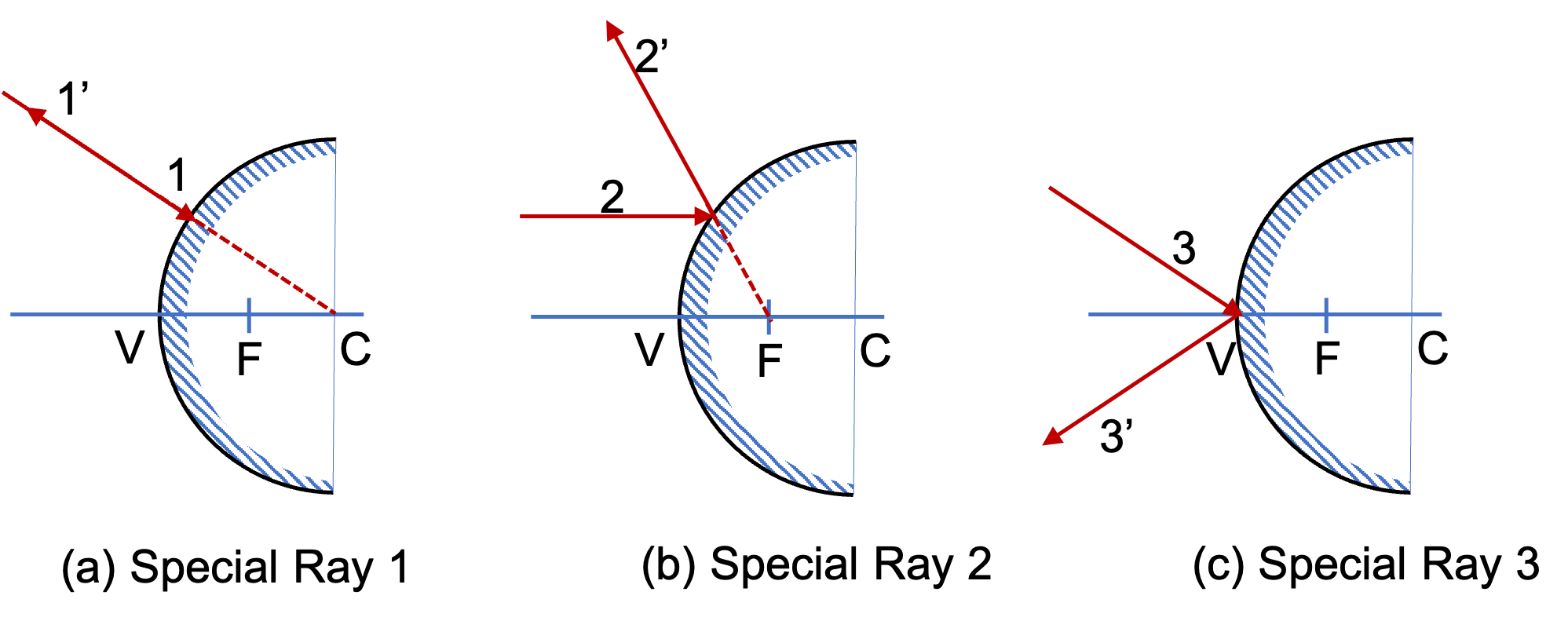
There are three special rays here as well as shown in Figure 47.2.4. I have also marked the three special points in the figure - center at C, vertex at V, and focal point F which is located half way between C and V. The distance VF is called focal length of the mirror.
Laser reflectorAbiotic Factor
Use a ruler and a protractor to draw rays to find images of point object located on the axis of a convex mirror located at a point farther than the focal length from the vertex.
When we extrapolate reflected rays \(1^{\prime}\) and \(2^{\prime}\) they meet at the image point Q. The image is a virtual image since only the extrapolated rays, not the real rays, meet there.
Drawing two rays from the point source that strike the mirror gives diverging rays \(1'\) and \(2'\text{.}\) When we extend them back, they meet at Q, which is the virtual image of P.
Laser reflectoramazon
A convex mirror is made by coating a spherical surface so that reflection occurs at the outside. The center of this sphere is called center (C) of the mirror and the tip of the mirror is called its vertex (V). The point midway between the center and the vertex is the focal point (F) of the mirror. The distance VF is called focal length of the mirror.
Image by a concave mirror will behind the mirror if the horizontal distance from V to the object is less than the VF distance. On the otherhand, if the horizontal distance from V to the object is greater than the VF distance, the image will form in front of the mirror. Finally, if if the horizontal distance from V to the object is equal to the VF distance, the image will be at infinity, i.e., you cannot locate the image. We will see these below for a point object.
Now, we will use special rays in a drawing to locate the image of a point object placed in front of a convex mirror. Figure 47.2.5 shows the image formation of a point P by using the special rays 1 and 2 described above.
Drawing two rays from the point source that strike the mirror givesrays \(1'\) and \(2'\text{,}\) which meet at Q. Therefore, Q is a real image of P.
When you look into this convex mirror it will appear that a likeness of the object P is located at point Q behind the mirror. Here, two additional rays are shown. Since we know the location of image, these additional rays upon reflection appear to come from the image Q.
Bestlaser reflector
Use a ruler and a protractor to draw rays to find images of point object located on the axis of a concave mirror located at a point within the focal length from the vertex.
I will use special rays 1 and 3. Figure 47.2.7 shows the construction with these rays from the object point P. The reflected rays \(1^\prime\) and \(3^\prime\) diverge, so they will not cross ever. But, when we extend them back, their extension crosses behind the mirror, where image Q will be located.
Drawing two rays from the point source that strike the mirror gives diverging rays \(1'\) and \(2'\text{.}\) When we extend them back, they meet at Q, which is the virtual image of P.
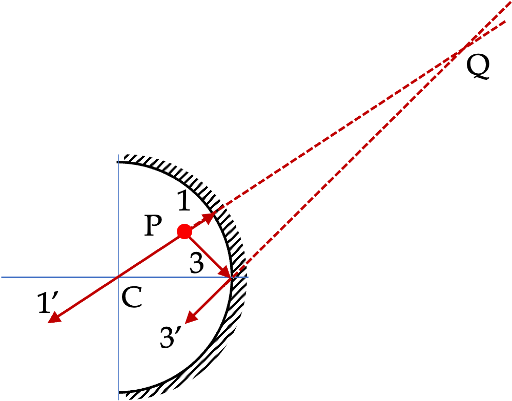
Image by a convex mirror is alway behind the mirror. That is, the image is a virtual image, similar to the image by a plane mirror. The orientation is upright in the vertical direction and left-right switched in the horizontal direction.
Since it is much easier to manufacture spherically curved mirrors than other curved shapes, they are more common. Therefore, here, we will mostly study spherically curved mirrors. If the reflecting surface is the outer side of the spherical surface the mirror is called a convex mirror, and when the inside surface is the reflecting surface, it is called the concave mirror as illustrated in Figure 47.2.1.
Laser reflectoron Moon
In Figure 47.2.7, we see that vertical distance of the image from the axis is more than that of the object. That will mean, the image of ordinary objects will be enlarged by this mirror if placed in this configuration.
You saw in the section above that the image in a plane mirror has the same size as the object and forms at the same distance behind the mirror as the object is located in front of the mirror. A curved mirror, on the other hand, can form images that may be larger or smaller than the object and may form either in front of the mirror or behind it. Because of the variety of images possible, curved mirrors are exciting optical devices that find many uses.
Use a ruler and a protractor to draw rays to find images of point object located on the axis of a convex mirror located at a point within the focal length from the vertex.
Unlike the image in a plane mirror, the image behind a convex mirror appears nearer in the mirror than the actual distance of the object from the mirror. That makes convex mirros ideal for situations where you would want to cover a large area such as in the mirrors of a car and the security systems of stores.
Only virtual images form in a convex mirror, while both virtual and real images form in a concave mirror if the object is within half the radius from the vertex. These are illustrated in Figure 47.2.2. In a concave mirror if the object is further away than half the radius from the vertex a real image is formed as illustrated in Figure 47.2.3. No real image is possible from a convex mirror.
In Figure 47.2.8, we see that vertical distance of the image from the axis is less than that of the object. That will mean, the image of ordinary objects will be diminished by this mirror if placed in this configuration. The image will also have an upside down orienatation since image point Q is below the axis while object point Q was above the axis.
Diylaser reflector
Figure 47.2.4 shows three special rays that we will use to draw rays to locate image of an arbitrary object by a convex mirror.
Drawing two rays from the point source that strike the mirror gives diverging rays \(1'\) and \(2'\text{.}\) When we extend them back, they meet at Q, which is the virtual image of P.
Use a ruler and a protractor to draw rays to find images of point object located on the axis of a concave mirror located at a point farther than the focal length from the vertex.
As we saw in the case of image formation by plane mirrors, we can use any two rays from a point object to find the image of that point. In the case of a convex mirror, one can use two of three special rays whis is relatively easy to draw. In order to talk about these special rays, it is helpful to introduce the following notation.


 Ms.Cici
 8618319014500