
ZEISS Microscopy Online Campus | Objectives - what does the objective lens do on a microscope
Compressed air is regular air, the volume of which has been decreased with the help of a compressor. This is how it is used and the benefits.
Dichroic MirrorDichroic mirrors are designed to reflect light whose wavelength is below a specific value (i.e. the cutoff wavelength) while permitting all other wavelengths to pass through it unaltered. In a microscope, the dichroic mirror directs the proper wavelength range to the sample as well as to the image plane. The cutoff wavelength value associated with each mirror indicates the wavelength that corresponds to 50% transmission. For example, as shown in the graph to the right, the cutoff wavelength for the Yellow Fluorescent Protein (YFP) Dichroic Mirror (MD515) is ~515 nm. The Specs tab provides information on the reflectance and transmission for each type of dichroic mirror.
A single fluorophore can be continually excited unless it is destroyed by photobleaching (i.e. the nonreversible destruction of a fluorophore due to photon-induced chemical damage or covalent modification). The average number of excitation and emission cycles that a particular fluorophore can undergo prior to photobleaching depends on its molecular structure and the local environment; some fluorophores bleach quickly after emitting only a few photons while others are far more robust and can undergo thousands or even millions of cycles before bleaching occurs.
Click on the below to view the filter set transmission with the absorption and emission spectra of the fluorophore. The key to the right details the meaning of all check marks in the table below. Please note that absorption and emission spectra are unavailable if any is red.
These filters provide excellent transmission of the desired excitation wavelength (>90%), with a sharp spectral cutoff and low transmission at other wavelengths (<0.001%). Click on the icons above to view product-specific transmission data. For additional fluorophore compatability, please see the Fluorophores tab.
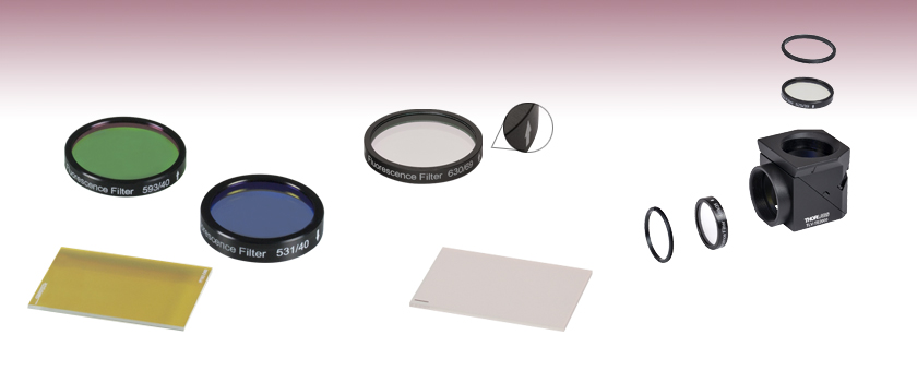
These excitation fluorescence imaging filters are specifically designed to be used in microscopy and imaging applications. Each Ø25 mm filter is mounted in a 5 mm thick black anodized housing. The housing has an arrow engraved on it that points in the recommended light propagation direction.
2014912 — A prism is a transparent, geometric, optical object with a minimum of two polished plane faces inclined relative to each other, from which light is reflected ...
Colorfilters
Sep 13, 2024 — The Fresnel lens, developed in 1822 by Augustine Fresnel, was the most magnificent lighthouse lens ever made. It was used in many of the world's ...
Lensimaging
OVERCOME BARREL DISTORTION WITH THESE 5 EASY TIPS · 1) SHOOT WITH A 50MM LENS (FULL FRAME SENSOR). On a 35mm format camera a focal length of 50mm is almost ...
2023322 — Wavelength Opto-Electronic design and manufacture ZnSe beam splitters at 9.4µm and 10.6µm wavelengths which are ideal for your CO2 laser ...
Each excitation or emission filter is housed in a Ø25 mm black anodized aluminum ring which makes handling easier and enhances the blocking OD by limiting scattering. These filters can be mounted in our extensive line of filter mounts and wheels. As the aluminum rings are not threaded, Ø1" retaining rings will be required to mount the Ø25 mm filters in one of our internally-threaded SM1 lens tubes. For customers who wish to use these filters in Thorlabs, Olympus, or Nikon fluorescence microscopes, Thorlabs manufactures a family of Drop-In Microscope Filter Cubes. Additionally, the unmounted 25 mm x 36 mm dichroic filters can be mounted in the KM2536 kinematic mount, which is designed to secure a 1 mm thick rectangular optic with minimal stress.
DielectricFilters
FluorophoresA fluorophore is a molecule or portion of a molecule that is capable of producing fluorescence. When light of the appropriate frequency necessary to excite a molecule from its ground state to an excited state is present, excitation will occur. However, once in an excited state, the molecule will be unstable. After some short period of time (typically 10-15 to 10-9 s), a photon will be released, thereby enabling the molecule to return to a lower energy state. The emitted radiation will be at a longer wavelength (lower energy) than the absorbed radiation due to the loss of energy through various mechanisms such as vibrations, sound, and thermal energy.
Description. PEC PADs are the ideal photo wipes for cleaning your film. PEC PADs are extremely strong, lint-free and so soft and pure it is almost impossible to ...
Filter DesignOur filters are manufactured to high-performance optical specifications and designed for durability. They are produced via multiple dielectric layers deposited on a high-precision, fused silica substrate. The substrate is ground and polished to ensure that the highest possible image quality is maintained. The resulting hard-coated optics consist of filter layers that are denser than those obtained from electron beam deposition techniques, and which reduce water absorption while greatly enhancing durability, stability, and performance of the filter. Each filter layer is monitored during growth to ensure minimal deviation from design specification thickness, ensuring overall high-quality filter performance.
Emission FilterAn emission filter serves the purpose of allowing the desirable fluorescence from the sample to reach the detector while blocking unwanted traces of excitation light. Like the excitation filter, this filter only allows a narrow band of wavelengths to pass through it, around the peak fluorophore emission wavelength. For example, as shown in the graph to the right, the bandpass region corresponding to greater than 90% transmission for the Yellow Fluorescent Protein (YFP) Emission Filter (MF535-22) is 524 - 546 nm; incident radiation outside of this range is either partially (for regions near the transmission region) or totally (for regions further from the bandpass region) blocked by the filter.
The table below displays all of the fluorophores that are compatible with our filter sets. The filter set item numbers are listed across the top row and the fluorophores are listed down the first column. Scroll through the table to view fluorophore compatibility with our filter sets.
Vn filter
Please Note: The excitation and emission filter housings have an arrow engraved on them that points in the recommended direction of light propagation. Dichroic filters have a marking on the side with the beamsplitter coating. Light should be incident on the marked side of the optic for optimal performance. For further fluorophore compatability, please see the Fluorophores tab.
Rca In-Line Ethernet Coupler (cat 5e) ... This website uses third party advertising cookies to serve you relevant ads. You may opt-out from these third party ad ...
MidwestFilters
These excitation, emission, and dichroic filters are designed specifically for use in fluorescence imaging applications. They are fabricated at industry-standard dimensions that make them compatible with filter cubes from all major manufacturers. We offer individual filters and filter sets targeted at common fluorophores: BFP, CFP, WGFP, GFP, FITC, Alexa Fluor® 488, YFP, tdTomato, TRITC, Texas Red, mCherry, and Cyanine (CY3.5). In addition, the Fluorophores tab provides information on the alternative fluorophores suitable for these filters. These filters are also available pre-installed into our microscope filter cubes.
Sep 26, 2024 — The Lens Distortion Correction algorithm is implemented by warping the distorted input image into a rectified, undistorted output image. · The ...
Edgefilters
Optical Glass Cube Dichroic Beam Splitter Prism Ratio 50:50 Spectrome Sicence : Amazon.ca: Toys & Games.
What is a laser? A laser consists of two fundamental elements: ... These two components are sufficient to amplify an existing light source. This is known as a ...
These filters provide excellent transmission of the desired emission wavelength (>90%), with a sharp spectral cutoff and low transmission at other wavelengths (<0.001%). Click on the icons above to view product-specific transmission data. For additional fluorophore compatability, please see the Fluorophores tab.
Long passfilters
Absorptivefilters
Filters for Fluorescence MicroscopyThe experimental setup to the right shows the typical filters used for epi-fluorescence microscopy, a form of microscopy in which both the excitation and emission light travel through the microscope objective. By carefully choosing the appropriate filters and mirrors for a given application, the signal-to-noise ratio can be maximized. As shown in the schematic to the right, three types of filters are used to maximize the fluorescence signal while minimizing the unwanted radiation. Each optical element is discussed below.
Thorlabs' Dichroic Filters are designed to separate light of different wavelengths. When light is incident on the filter at a 45° angle with respect to the normal, the excitation light and its associated back reflection are reflected while the longer wavelength fluorescence signal is transmitted. These filters are unmounted, but are marked by a dash to indicate the coated side of the filter, which light should be incident on. Each filter is 25.0 mm x 36.0 mm. If your application would benefit from a round, mounted dichroic filter, consider our round Dichroic Filters. Click on the icons above to view product-specific transmission data. For further fluorophore compatability, please see the Fluorophores tab.
Although dichroic mirrors play a crucial role in fluorescence microscopy, they are not perfect when it comes to blocking unwanted light; typically, ~90% of the light at wavelengths below the cutoff wavelength value are reflected and ~90% of the light at wavelengths above this value are transmitted by the dichroic mirror. Hence, some of the excitation light can be transmitted through the dichroic mirror along with the longer wavelength fluorescence emitted by the sample. To prevent this unwanted light from reaching the detection system, an emission filter is used in addition to the dichroic mirror.
By placing one of these mirrors into the experimental setup at 45° with respect to the incident radiation, the excitation radiation (shown in blue in the above right schematic) is reflected off of the surface of the dichroic mirror and directed towards the sample and microscope objective, while the fluorescence emanating from the sample (shown in red in the above right schematic) passes through the mirror to the detection system.
Dichroic filters are marked on the side with the dichroic coating. Light should be incident on this side for best performance.
Since standard fluorescence imaging applications generally incorporate three different filters (i.e., one excitation, one emission, and one dichroic filter) to maximize the signal-to-noise ratio, Thorlabs offers these filters as a set at a savings over purchasing them separately.
These emission fluorescence imaging filters are specifically designed to be used in microscopy and imaging applications. Each Ø25 mm filter is mounted in a 3.5 mm thick black anodized housing. The housing has an arrow engraved on it that points in the recommended light propagation direction.
Excitation FilterThe excitation filter only allows a narrow band of wavelengths to pass through it, around the peak fluorophore excitation wavelength. For example, as shown in the graph to the right, the bandpass region corresponding to greater than 90% transmission for the Yellow Fluorescent Protein (YFP) Excitation Filter (MF497-16) is 489 - 505 nm; incident radiation outside of this range is either partially (for regions near the transmission region) or totally (for regions further from the bandpass region) blocked by the filter.


 Ms.Cici
 8618319014500