
ZEISS Microscopy Online Campus | Microscope Optical Systems - microscope ocular lens function
Wang X, Wang X, Zhou P, Su R, Geng C, Li X, Xu X, Shu B (2012) 350-W coherent beam combining of fiber amplifiers with tilt-tip and phase-locking control. IEEE Photon Technol Lett 24:1781–1784
The imaging medium between the objective front lens and the specimen cover slip is another important element in respect to correction for spherical aberration and coma in the design of lens elements for objectives. Lower power objectives are designed to be used with only air as the imaging medium between the objective front lens and the coverslip. The maximum theoretical numerical aperture obtainable with air is 1.0, however in practice it is virtually impossible to produce a dry objective with a numerical aperture above 0.95. The effect of coverslip thickness variation is negligible for dry objectives having numerical apertures less than 0.4, but such deviation becomes significant at numerical apertures exceeding 0.65, where fluctuations as small as 0.01 millimeter can introduce spherical aberration.
Poulton CV, Byrd MJ, Russo P, Timurdogan E, Khandaker M, Vermeulen D, Watts MR (2019) Long-range LiDAR and free-space data communication with high-performance optical phased arrays. IEEE J Sel Top Quantum Electron 25:1–8
Dixit A, Sooraj MS, Linslal CL, Padmanabhan A, Venkitesh D, Srinivasan B (2021) Experimental validation of free-space coherent beam combining simulations for filled aperture configuration. In: Conference on lasers and electro-optics (CLEO 2021), OSA technical digest (Optical Society of America)
Scanningobjectivelens
Ma Y, Zhou P, Wang X, Ma H, Xu X, Si L, Liu Z, Zhao Y (2011b) Active phase locking of fiber amplifiers using sine-cosine single-frequency dithering technique. Appl Opt 50:3330–3336
A majority of the microscope objectives being produced today offer extraordinarily low degrees of aberration and other imperfections, assuming the appropriate objective is selected and utilized properly. Even still, the microscopist must be conscious of the fact that objectives are not perfectly crafted from every standpoint, but are designed to meet a certain set of qualifications depending on intended use, constraints on physical dimensions, and price ranges. Consequently, objectives are made with degrees of correction that differ for chromatic and spherical aberration, field size and flatness, transmission wavelengths, freedom from fluorescence, birefringence, and additional factors contributing to background noise. Additionally, they are intended to be used under certain limited conditions, such as with particular tube lengths and tube lenses, type and thickness of immersion media and coverslips, wavelength ranges, field sizes, ocular types, and special condensers.
Ayyaswamy P, Linslal CL, Dixit A, Venkitesh D, Srinivasan B (2021) Data-driven modeling of phase noise sources in coherent beam combining. In: Laser applications conference, OSA laser congress
The third type of objective, the apochromatic objective, possesses the highest level of correction (Figure 2). Lower power apochromat objectives (5x, 10x, and 20x) have a longer working distance than higher power (40x and 100x) apochromat objectives. Apochromats almost eliminate chromatic aberration, are usually corrected chromatically for three colors (red, green, and blue), and are corrected spherically for either two or three wavelengths (see Table 1). Apochromatic objectives are the best choice for color photomicrography in white light. Because of their high level of correction, apochromat objectives usually have, for a given magnification, higher numerical apertures than do achromats or fluorites. Many of the newer high-performance fluorite and apochromat objectives are corrected for four (dark blue, blue, green, and red) or more colors chromatically and four colors spherically.
Stiles E (2009) New developments in IPG fiber laser technology. In: Proceedings of the 5th international workshop on fiber lasers
In situations where the specimen is designed to be imaged without a coverslip, the working distance is measured at the actual surface of the specimen. Working distance typically decreases in a series of matched objectives as the magnification and numerical aperture increase. Objectives intended to view specimens with air as the imaging medium should have comparatively long working distances providing that numerical aperture requirements are satisfied. Alternatively, immersion objectives should have shallower working distances in order to keep the immersion liquid between the front lens and the specimen in place. Many objectives designed with similar working distances have a spring-loaded retraction stopper that allows the front lens assembly to be withdrawn by pushing it into the objective body and twisting to secure its place. Twisting the retraction stopper in the opposite direction releases the lens assembly for use. In some applications (see below), a long free working distance is indispensable, and special objectives are designed for such use despite how difficult it is to achieve large numerical apertures and the necessary degree of optical correction.
Oil immersionobjective microscope function
All three types of objectives suffer from pronounced field curvature, thus they project curved images rather than flat ones. Such artifact increases in severity with higher magnification. To overcome this inherent condition, optical designers have produced flat-field corrected objectives, which yield images that are in common focus throughout the viewfield. Objectives that have flat-field correction and low distortion are called plan achromats, plan fluorites, or plan apochromats, depending upon their degree of residual aberration. This correction, although expensive, is extremely valuable in digital imaging and conventional photomicrography.
Anderegg J, Brosnan S, Cheung E, Epp P, Hammons D, Komine H, Weber M, Wickham M (2006) Coherently coupled high-power fiber arrays. In: Proceedings of SPIE 6102, fiber lasers III: technology, systems, and applications, 61020U (23 February)
Objectivelens magnification
Bai Y, Lei G, Chen H, Feng X, Li D, Bai J (2019) Incoherent space beam combining of fiber-transmitted semiconductor lasers for oil well laser perforation. IEEE Access 7:154457–154465
Satyan N, Vasilyev A, Rakuljic G, White JO, Yariv A (2012) Phase-locking and coherent power combining of broadband linearly chirped optical waves. Opt Express 20:25213–25227
Shay TM, Baker JT, Sanchez AD, Robin CA, Vergien CL, Zeringue C, Gallant D, Lu CA, Pulford B, Bronder TJ, Lucero A (2009) High-power phase locking of a fiber amplifier array. In: Proceedings of SPIE 7195, fiber lasers VI: technology, systems, and applications, 71951M (19 February)
Nosepiecemicroscope function
Flores A, Dajani I, Holten RH, Ehrenreich T, Anderson BT (2016) Multi-kilowatt diffractive coherent combining of pseudorandom-modulated fiber amplifiers. Opt Eng 55(9):096101
Augst SJ, Fan TY, Sanchez A (2004) Coherent beam combining and phase noise measurements of ytterbium fiber amplifiers. Opt Lett 29:474–476
Zhi D, Zhang Z, Ma Y, Wang X, Chen Z, Wu W, Zhou P, Si L (2017) Realization of large energy proportion in the central lobe by coherent beam combination based on conformal projection system. Sci Rep 7:2199
Prossotowicz M, Flamm D, Heimes A, Jansen F, Otto H, Budnicki A, Killi A, Morgner U (2021) Dynamic focus shaping with mixed-aperture coherent beam combining. Opt Lett 46:1660–1663
The authors would like to acknowledge funding support by DRDO Laser Science & Technology Centre (LASTEC) and Centre for High Energy Systems & Sciences (CHESS) through Contract for Acquisition of Research Services (CARS) projects, and MHRD/DRDO, Government of India through the Impacting Research Innovation and Technology scheme (IMPRINT/5375), as well as technical discussions with Drs. Anup Shah and Jagannath Nayak. The authors are thankful to Prof. Johan Nilsson and Dr. Yusuf Panbiharwala for the technical discussions.
Sumida DS, Jones DC, Rockwell DA (1994) An 8.2 J phase-conjugate solid-state laser coherently combining eight parallel amplifiers. IEEE J Quantum Electron 30:2617–2627
When the objective is assembled, spherical aberration is corrected by selecting the best set of spacers to fit between the hemispherical and meniscus lens (the lower lens mounts). The objective is parfocalized by translating the entire lens cluster upward or downward within the sleeve with locking nuts so that focus will not be lost while objectives housed on a multiple nosepiece are interchanged. Adjustment for coma is accomplished with three centering screws that optimize the position of internal lens groups with respect to the optical axis of the objective.
Shirakawa A, Saitou T, Sekiguchi T, Ueda K (2002) Coherent addition of fiber lasers by use of a fiber coupler. Opt Express 10:1167–1172
In the past 100 years, construction techniques and materials used to manufacture objectives have greatly improved. Composed up of numerous internal glass lens elements, modern objectives have reached a high state of quality and performance considering the extent of correction for aberrations and flatness of field. Objectives are currently designed with the assistance of Computer-Aided-Design (CAD) systems, which use advanced rare-element glass formulations of uniform composition and quality characterized by highly specific refractive indices. These advanced techniques have allowed manufacturers to produce objectives that are very low in dispersion and corrected for most of the common optical artifacts such as coma, astigmatism, geometrical distortion, field curvature, spherical and chromatic aberration. Not only are microscope objectives now corrected for more aberrations over wider fields, but image flare has been dramatically reduced thanks to modern coating technologies, with a substantial increase in light transmission, yielding images that are remarkably bright, sharp, and crisp.
Mediumpower objective microscope function
Zhou P, Liu Z, Wang X, Ma Y, Ma H, Xu X, Guo S (2009) Coherent beam combining of fiber amplifiers using stochastic parallel gradient descent algorithm and its application. IEEE J Sel Top Quantum Electron 15:248–256
Billaud A, Gomez F, Allioux D, Laurenchet N, Jian P, Pinel O, Labroille G (2020) Optimal coherent beam combining based on Multi-Plane Light Conversion for high throughput optical feeder links (conference presentation). In: Proceedings of SPIE 11272,free-space laser communications XXXII
Qiu Y, Xie Y, Wang W, Liu W, Kuang L, Bai X, Hu M, Ho J (2019) Ultra-high-power and high-efficiency 905 nm pulsed laser for LiDAR. In: 2019 IEEE 4th optoelectronics global conference (OGC), pp 32–35
Redmond SM, Ripin DJ, Yu CX, Augst SJ, Fan TY, Thielen PA, Rothenberg JE, Goodno GD (2012) Diffractive coherent combining of a 2.5 kW fiber laser array into a 1.9 kW Gaussian beam. Opt Lett 37:2832–2834
Song H, Yan D, Wu W, Shen B, Feng X, Liu Y, Li L, Chu Q, Li M, Wang J, Tao R (2021) SRS suppression in multi-kW fiber lasers with a multiplexed CTFBG. Opt Express 29:20535–20544
Huo Y, Cheo PK, King GG (2004) Fundamental mode operation of a 19-core phase-locked Yb-doped fiber amplifier. Opt Express 12:6230–6239
Carlson NW, Evans GA, Hammer JM, Lurie M, Palfrey SL, Dholakia A (1987) Phase-locked operation of a grating-surface-emitting diode laser array. Appl Phys Lett 50:1301–1303
Wang M, Liu L, Wang Z, Xi X, Xu X (2019) Mitigation of stimulated Raman scattering in kilowatt-level diode-pumped fiber amplifiers with chirped and tilted fiber Bragg gratings. High Power Laser Sci Eng 7
Goodno GD, McNaught SJ, Rothenberg JE, McComb TS, Thielen PA, Wickham MG, Weber ME (2010a) Active phase and polarization locking of a 1.4 kW fiber amplifier. Opt Lett 35:1542–1544
Augst SJ, Ranka JK, Fan TY, Sanchez A (2007) Beam combining of ytterbium fiber amplifiers (Invited). J Opt Soc Am B 24:1707–1715
Rothenberg JE, Thielen PA, Wickham M, Asman CP (2008) Suppression of stimulated Brillouin scattering in single-frequency multi-kilowatt fiber amplifiers. In: Proceedings of SPIE 6873, fiber lasers V: technology, systems, and applications, 68730O (22 February)
Zhou T, Sano T, Wilcox R (2017a) Coherent combination of ultrashort pulse beams using two diffractive optics. Opt Lett 42:4422–4425
Erin E. Wilson and Michael W. Davidson - National High Magnetic Field Laboratory, 1800 East Paul Dirac Dr., The Florida State University, Tallahassee, Florida, 32310.
Tünnermann H, Shirakawa A (2020) Tiled aperture beam combining with reinforcement learning. In: 2020 conference on lasers and electro-optics (CLEO), pp 1–2
Honea E, Afzal RS, Savage-Leuchs M, Henrie J, Brar K, Kurz N, Jander D, Gitkind N, Hu D, Robin C, Jones AM, Kasinadhuni R, Humphreys R (2016) Advances in fiber laser spectral beam combining for power scaling. In: Proceedings ’components and packaging for laser systems II’, vol 9730
Tünnermann H, Shirakawa A (2019) Deep reinforcement learning for coherent beam combining applications. Opt Express 27:24223–24230
Leger JR, Scott ML, Veldkamp WB (1988) Coherent addition of AlGaAs lasers using microlenses and diffractive coupling. Appl Phys Lett 52:1771–1773
Thielen PA, Ho JG, Burchman DA, Goodno GD, Rothenberg JE, Wickham MG, Flores A, Lu CA, Pulford B, Robin C, Sanchez AD, Hult D, Rowland KB (2012) Two-dimensional diffractive coherent combining of 15 fiber amplifiers into a 600 W beam. Opt Lett 37:3741–3743
For several years, most manufacturers conformed to an international standard of parfocal distance when designing objective lenses for biological applications. As a result, a majority of objectives had a parfocal distance of 45.0 millimeters and were considered interchangeable. As it became commonplace to produce infinity-corrected tube lengths, a new set of design criteria was created to correct for aberrations in the objective and tube lenses. Alongside a demand for greater flexibility to accommodate the requirement of expanding working distances with higher numerical apertures and field sizes, interchangeability between objective lenses from different manufacturers is now more limited.
Baumeister T, Brunton SL, Kutz JN (2018) Deep learning and model predictive control for self-tuning mode-locked lasers. J Opt Soc Am B 35:617–626
Shiner B (2013) The impact of fiber laser technology on the world wide material processing market. In: Proceedings of the CLEO, OSA, San Jose, CA, USA, p AF2J.1
Wang X, Ma Y, Zhou P, He B, Xiao H, Xue Y, Liu C, Li Z, Xu X, Zhou J, Liu Z, Zhao Y (2011) Coherent beam combining of 137W 2×2 fiber amplifier array. Opt Commun 284:2198–2201
Anderegg J, Brosnan SJ, Weber ME, Komine H, Wickham MG (2003) 8-W coherently phased 4-element fiber array. In; Proceedings of SPIE 4974, advances in fiber lasers (3 July)
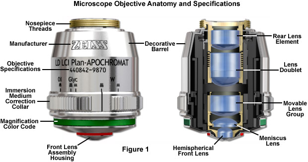
Major microscope manufacturers offer a wide range of objective designs that feature excellent optical characteristics under a wide spectrum of illumination conditions and provide various degrees of correction for the primary optical aberrations. The objective illustrated in Figure 1 is a 20x multi-immersion media plan-apochromat, which contains 9 optical elements that are cemented together into two groups of lens doublets, a movable lens triplet group, and two individual internal single-element lenses. The objective also has a hemispherical front lens and a meniscus second lens, which work synchronously to assist in capturing light rays at high numerical aperture with a minimum of spherical aberration. Many high magnification objectives are equipped with a spring-loaded retractable nosecone assembly that protects the front lens elements and the specimen from collision damage. Internal lens elements are carefully oriented and tightly packed into a tubular brass housing that is encapsulated by the decorative objective barrel. Specific objective parameters such as numerical aperture, magnification, optical tube length, degree of aberration correction, and other important characteristics are imprinted or engraved on the external portion of the barrel. The objective featured in Figure 1 is designed to operate utilizing water, glycerin, or a specialized hydrocarbon-based oil as the imaging medium.
Hou T, Chang Q, Chang H, Liu W, Ma P, Su R, Ma Y, Zhou P (2020) Structuring orbital angular momentum beams by coherent laser array systems with tip-tilt optimization. Results Phys 19:103602
Goodno GD, Shih C, Rothenberg JE (2010b) Perturbative analysis of coherent combining efficiency with mismatched lasers. Opt Express 18:25403–25414
Wang D, Du Q, Zhou T, Li D, Wilcox R (2021) Stabilization of the 81-channel coherent beam combination using machine learning. Opt Express 29:5694–5709
If you take a look at the objective barrel, you will discover that there is a large amount of detail inscribed on it. Each objective is inscribed with the magnification; the tube length for which the objective was designed to give its finest images; and the thickness of coverslip protecting the specimen, which the designer assumed to have a constant value, correcting for spherical aberration. The objective will be engraved OIL or OEL or HI if the objective is designed to function with immersion oil. If not, the objective is meant to be used dry. Objectives are also always engraved with their numerical aperture value. If the objective does not indicate a higher correction, it is most likely an achromatic objective (more highly corrected objectives have inscriptions such as apochromat or apo, plan, FL, fluor, etc).
Bruesselbach H, Wang S, Minden M, Jones DC, Mangir M (2005b) Power-scalable phase-compensating fiber-array transceiver for laser communications through the atmosphere. J Opt Soc Am B 22:347–353
Linslal, C.L., Ayyaswamy, P., Maji, S. et al. Challenges in coherent beam combining of high power fiber amplifiers: a review. ISSS J Micro Smart Syst 11, 277–293 (2022). https://doi.org/10.1007/s41683-022-00099-4
Li X, Xiao H, Dong X, Ma Y, Xu X (2011) Coherent beam combining of two slab laser amplifiers and second-harmonic phase locking based on a multi-dithering technique. Chin Phys Lett 28:094210
A dramatic improvement in contrast and transmission of visible wavelengths is the result of most microscope manufacturers currently producing their own proprietary formulations, along with a simultaneous destructive interference in harmonically-related frequencies lying outside the transmission band. The microscopist should be aware of the fact that these specialized coatings can be easily damaged by mis-handling. A good rule to employ in order to distinguish between coatings is that multilayer antireflection coatings have a slightly greenish tint, as opposed to the purplish tint of single-layer coatings. Also, the surface layer of antireflection coatings used on internal lenses is often much softer than corresponding coatings. Special care should be taken when cleaning optical surfaces that have been coated with thin films, especially if the microscope has been disassembled and the internal lens elements are subject to inspection.
Corcoran CJ, Rediker RH (1991) Operation of five individual diode lasers as a coherent ensemble by fiber coupling into an external cavity. Appl Phys Lett 59:759–761
A number 1½ coverslip is standard, with a thickness of 0.17 millimeters. Unfortunately, not all 1½ coverslips are manufactured to this standard (they range from 0.16 to 0.19 millimeters), and many specimens have media between them and the coverslip. By adjusting the mechanical tube length of the microscope, or by the utilization of specialized correction collars, compensation for coverslip thickness can be provided. Objective numerical aperture can be radically increased if the objective is used with an immersion medium such as oil, glycerin, or water. Typical immersion oils have a refractive index of 1.51 and a dispersion profile similar to that of glass cover slips. An immersion medium with a refractive index similar to that of the glass cover slip will practically eliminate image degradation due to thickness variations of the coverslip whereby rays of wide obliquity no longer undergo refraction and are more readily grasped by the objective. Light rays passing through the specimen encounter a homogeneous medium between the cover slip and immersion oil and are not refracted as they enter the lens, but only as they leave its upper surface. Therefore, if the specimen is placed at the aplanatic point of the first objective lens, imaging this portion of the lens system is totally free of spherical aberration.
Kim J, Dupriez P, Codemard C, Nilsson J, Sahu JK (2006) Suppression of stimulated Raman scattering in a high power Yb-doped fiber amplifier using a W-type core with fundamental mode cut-off. Opt Express 14:5103–5113
Geng C, Luo W, Tan Y, Liu H, Mu J, Li X (2013) Experimental demonstration of using divergence cost-function in SPGD algorithm for coherent beam combining with tip/tilt control. Opt Express 21:25045–25055
Goodno GD, Asman CP, Anderegg J, Brosnan S, Cheung EC, Hammons D, Injeyan H, Komine H, Long WH, McClellan M, McNaught SJ, Redmond S, Simpson R, Sollee J, Weber M, Weiss SB, Wickham M (2007) Brightness-scaling potential of actively phase-locked solid-state laser arrays. IEEE J Sel Top Quantum Electron 13:460–472
Coherent combining of light from multiple high power fiber amplifiers is a promising pathway to scaling the output power to hundreds of kiloWatts. In the last decade, substantial progress has been made in terms of scaling number of elements along with improvement in phase control techniques to achieve stable locking, resulting in tens of kiloWatts of output power. In this paper, we review the progress in coherent beam combining of fiber amplifiers in the master oscillator power amplifier configuration. We also discuss the challenges in power scaling as well as the current trends in the corresponding mitigation strategies. Specifically, the use of optimized phase modulation waveforms for mitigation of stimulated Brillouin scattering in high power amplifiers, scaling of the number of beam combining elements through deep-learning based phase control, and the use of micro-lens array for enhancing beam combination efficiency are discussed.
Chang H, Chang Q, Xi J, Hou T, Su R, Ma P, Wu J, Li C, Jiang M, Ma Y, Zhou P (2020) First experimental demonstration of coherent beam combining of more than 100 beams. Photon Res 8:1943–1948
Kono Y, Takeoka M, Uto K, Uchida A, Kannari F (2000) A coherent all-solid-state laser array using the Talbot effect in a three-mirror cavity. IEEE J Quantum Electron 36:607–614
Microscope manufacturers produce objectives with restricted tolerances to refractive index and dispersion. This means they require matching values in the liquid placed between the coverslip and objective front lens. It is advisable to employ only the oil intended by the objective manufacturer, and to not mix immersion oils between manufacturers. Additionally, objectives that use water and/or glycerin as an imaging medium are also available for applications with living cells in culture or sections of tissue immersed in physiological saline solution.
The most common objectives used on laboratory microscopes are the achromatic objectives. Such objectives are corrected for axial chromatic aberration in blue and red wavelengths, which are about 486 and 656 nanometers, respectively. Both are brought into a single common focal point. Achromatic objectives are also corrected for spherical aberration in the color green (546 nanometers; see Table 1). Achromatic objectives' limited correction can result in images with a magenta halo if focus is chosen in the green region of the spectrum. The lack of correction for flatness of field (or field curvature) presents a further problem. Plan achromats provide flat-field corrections for achromat objectives (Figure 2). An even higher level of correction and cost is found in objectives called fluorites or semi-apochromats (illustrated by center objective in Figure 2), named for the mineral fluorite, which was originally used in their construction.
The most important imaging component in the optical microscope is the objective, a complex multi-lens assembly that focuses light waves originating from the specimen and forms an intermediate image that is subsequently magnified by the eyepieces. Objectives are responsible for primary image formation and play a central role in establishing the quality of images that the microscope is capable of producing. Furthermore, the magnification of a particular specimen and the resolution under which fine specimen detail also heavily depends on microscope objectives. The most difficult component of an optical microscope to design and assemble, the objective is the first element that light encounters as it passes from the specimen to the image plane. Objectives received name from the fact that they are, by proximity, the closest component to the object, or specimen, being imaged.
Charles Lailabai Linslal, Padmanabhan Ayyaswamy, Satyajit Maji, Mundakkolly Sureshbabu Sooraj, Awakash Dixit, Deepa Venkitesh & Balaji Srinivasan
Shpakovych M, Maulion G, Kermene V, Boju A, Armand P, Desfarges-Berthelemot A, Barthélemy A (2021) Experimental phase control of a 100 laser beam array with quasi-reinforcement learning of a neural network in an error reduction loop. Opt Express 29:12307–12318
Stage clipsmicroscope function
Flores A, Shay TM, Lu CA, Robin C, Pulford B, Sanchez AD, Hult DW, Rowland KB (2011) Coherent beam combining of fiber amplifiers in a kW regime. In CLEO:2011—laser applications to photonic applications, OSA technical digest (CD) (Optical Society of America)
Fan X, Liu J, Liu J, Wu J (2010) Coherent combining of a seven-element hexagonal fiber array. Opt Laser Technol 42:274–279
Older objectives typically have lower numerical apertures, and are subject to chromatic difference of magnification, an aberration that requires correction by the use of specially designed compensating oculars or eyepieces. This type of correction was prevalent during the popularity of fixed tube length microscopes, but is not necessary with modern infinity-corrected objectives and microscopes. Recently, correction for chromatic difference of magnification is either built into the modern microscope objectives themselves (Olympus and Nikon), or corrected in the tube lens (Leica and Zeiss). The intermediate image in an infinity-corrected system appears behind the tube lens in the optical pathway at the reference focal length. The tube lens focal length varies between 160 and 250 millimeters, depending upon design constraints imposed by the manufacturer. By dividing the reference focal length by the focal length of the objective lens, the magnification of an infinity-corrected objective can be calculated.
Liu Y, Lv Z, Dong Y, Li Q (2009) Research on stimulated Brillouin scattering suppression based on multi-frequency phase modulation. Chin Opt Lett 7:29–31
Klenke A, Müller M, Stark H, Tünnermann A, Limpert J (2018) Sequential phase locking scheme for a filled aperture intensity coherent combination of beam arrays. Opt Express 26:12072–12080
Jabczyński JK, Gontar P (2021) Impact of atmospheric turbulence on coherent beam combining for laser weapon systems. Defence Technol 17:1160–1167
Azarian A, Bourdon P, Lombard L, Jaouën Y, Vasseur O (2014) Orthogonal coding methods for increasing the number of multiplexed channels in coherent beam combining. Appl Opt 53:1493–1502
where Resolution is the minimum separation distance between two point objects that are clearly resolved, λ is the illumination wavelength, n is the imaging medium refractive index, and θ is equal to one-half of the objective angular aperture. With this in mind, it is apparent that resolution is directly proportional to the illumination wavelength. The human eye responds to the wavelength region between 400 and 700 nanometers, which represents the visible light spectrum that is utilized for a majority of microscope observations. Resolution is also dependent upon the refractive index of the imaging medium and the objective angular aperture. Objectives are intended to image specimens either through air or a medium of higher refractive index between the front lens and the specimen. The field of view is often highly restricted, and the front lens element of the objective is placed close to the specimen with which it must lie in optical contact. A gain in resolution by a factor of about 1.5 is attained when immersion oil is substituted for air as the imaging medium.
Moyer RH, Valley M, Cimolino MC (1988) Beam combination through stimulated Brillouin scattering. J Opt Soc Am B 5:2473–2489
Montoya J, Hwang C, Martz D, Aleshire C, Fan TY, Ripin DJ (2017) Photonic lantern kW-class fiber amplifier. Opt Express 25:27543–27550
Jones DC, Turner AJ, Scott AM, Stone SM, Clark RG, Stace C, Stacey CD (2010) A multi-channel phase locked fibre bundle laser. In: Proceedings of SPIE 7580, fiber lasers VII: technology, systems, and applications, 75801V (17 February)
Labroille G, Denolle B, Jian P, Genevaux P, Treps N, Morizur J (2014) Efficient and mode selective spatial mode multiplexer based on multi-plane light conversion. Opt Express 22:15599–15607
Prossotowicz M, Heimes A, Flamm D, Jansen F, Otto H, Budnicki A, Killi A, Morgner U (2020) Coherent beam combining with micro-lens arrays. Opt Lett 45:6728–6731
Zhu J, Zhou P, Ma Y, Xu X, Liu Z (2011) Power scaling analysis of tandem-pumped Yb-doped fiber lasers and amplifiers. Opt Express 19:18645–18654
Hou T, An Y, Chang Q, Ma P, Li J, Zhi D, Huang L, Su R, Wu J, Ma Y, Zhou P (2019) Deep-learning-based phase control method for tiled aperture coherent beam combining systems. High Power Laser Sci Eng 7:e59
Panbiharwala Y, Harish AV, Feng Y, Venkitesh D, Nilsson J, Srinivasan B (2021) Stimulated Brillouin scattering mitigation using optimized phase modulation waveforms in high power narrow linewidth Yb-doped fiber amplifiers. Opt Express 29:17183–17200
Vikram BS, Prakash R, Balaswamy V, Supradeepa VR (2021) Determination and analysis of line-shape induced enhancement of stimulated Brillouin scattering in noise broadened, narrow linewidth, high power fiber lasers. IEEE Photon J 13:1–12. https://doi.org/10.1109/JPHOT.2021.3067350
White JO, Young JT, Wei C, Hu J, Menyuk CR (2019) Seeding fiber amplifiers with piecewise parabolic phase modulation for high SBS thresholds and compact spectra. Opt Express 27:2962–2974
Uberna R, Bratcher A, Alley TG, Sanchez AD, Flores AS, Pulford B (2010) Coherent combination of high power fiber amplifiers in a two-dimensional re-imaging waveguide. Opt Express 18:13547–13553
Yu CX, Augst SJ, Redmond SM, Goldizen KC, Murphy DV, Sanchez A, Fan TY (2011) Coherent combining of a 4 kW, eight-element fiber amplifier array. Opt Lett 36:2686–2688
Hansryd J, Dross F, Westlund M, Andrekson PA, Knudsen SN (2001) Increase of the SBS threshold in a short highly nonlinear fiber by applying a temperature distribution. J Light Technol 19:1691–1697
Müller M, Aleshire C, Klenke A, Haddad E, Légaré F, Tünnermann A, Limpert J (2020) 10.4 kW coherently combined ultrafast fiber laser. Opt Lett 45:3083–3086
In many biological and petrographic applications, when mounting the specimen, a glass coverslip is used to both protect the integrity of the specimen and to provide a clear window for observation. The coverslip acts to converge the light cones originating from each point in the specimen. But it also introduces chromatic and spherical aberration that must be corrected by the objective. The refractive index, dispersion, and thickness of the coverslip determine the degree to which light rays are converged. An additional concern is the aqueous solvent or excess mounting medium that lies between the specimen and coverslip in wet or thickly mounted preparations, which add to the variations in refractive index and thickness of the cover slip.
The rear aperture or exit pupil of the objective restricts the light rays as they pass through an objective. The diameter of this aperture varies between 12 millimeters for low magnification objectives down to around 5 millimeters for the highest power apochromatic objectives. Close consideration of aperture size is absolutely imperative for epi-illumination applications that rely on the objective to act as both an imaging system and condenser, where the exit pupil also becomes an entrance pupil. The image of the light source must entirely fill the objective rear aperture to produce even illumination across the viewfield. If the light source image is smaller than the aperture, the viewfield will experience vignetting from uneven illumination. Conversely, if the light source image is larger than the rear aperture, all of the light will not enter the objective and the intensity of illumination is reduced.
Jin Y, Hassan A, Jiang Y (2016) Freeform microlens array homogenizer for excimer laser beam shaping. Opt Express 24:24846–24858
Harish AV, Nilsson J (2015) Optimization of phase modulation with arbitrary waveform generators for optical spectral control and suppression of stimulated Brillouin scattering. Opt Express 23:6988–6999
It is possible to correct for variations in coverslip thickness. Several high-performance apochromat dry objectives are fitted with correction collars that allow adjustment by a rotating collar, which causes two of the lens element groups in the objective to move closer together or farther apart (see Figure 4). Various specialized phase contrast objectives that are designed for tissue culture observation with an inverted microscope have an even broader compensation range of between 0 to 2 millimeters. In this way, specimens can be viewed through the bottom of most culture vessels, which in this size range, often have dramatic thickness fluctuations.
Liu Z, Ma P, Su R, Tao R, Ma Y, Wang X, Zhou P (2017) High-power coherent beam polarization combination of fiber lasers: progress and prospect [Invited]. J Opt Soc Am B 34:A7–A14
One of the most significant improvements in objective design during recent years is the enhancement of antireflection coating technology, which aides in reducing unnecessary reflections that occur as light passes through the lens system. Each uncoated air-glass interface is capable of reflecting between four and five percent of an incident light beam normal to the surface, resulting in a transmission value of 95-96 percent at normal incidence. If a quarter-wavelength thick antireflection coating with the appropriate refractive index is applied, it can increase this value by three to four percent. Multilayer coatings, which produce transmission values exceeding 99.9 percent in the visible spectral range, have replaced the single-layer lens coatings once used to reduce glare and improve transmission.
Dawson JW, Messerly MJ, Beach RJ, Shverdin MY, Stappaerts EA, Sridharan AK, Pax PH, Heebner JE, Siders CW, Barty CPJ (2008) Analysis of the scalability of diffraction-limited fiber lasers and amplifiers to high average power. Opt Express 16:13240–13266
Yu-Hao X, Bing H, Jun Z, Zhen L, Yuan-Yuan F, Yun-Feng Q, Chi L, Zhi-Jun Y, Hai-Bo Z, Qi-Hong L (2011) High power passive phase locking of four Yb-doped fiber amplifiers by an all-optical feedback loop. Chin Phys Lett 28:054212
There are three vital design characteristics of the objective that set the ultimate resolution limit of the microscope: The wavelength of light used to illuminate the specimen, the angular aperture of the light cone captured by the objective, and the refractive index in the object space between the objective front lens and the specimen. Resolution for a diffraction-limited optical microscope can be described as the minimum visible distance between two closely spaced specimen points:
Song J, Li Y, Che D, Guo J, Wang T (2020) Coherent beam combining based on the SPGD algorithm with a momentum term. Optik 202:163650
Tünnermann H, Shirakawa A (2018) Reinforcement learning for coherent beam combining. In: 2018 conference on lasers and electro-optics Pacific Rim (CLEO-PR), pp 1–2
Cao J, Zhao X, Liu W, Gu H (2017) Performance analysis of a coherent free space optical communication system based on experiment. Opt Express 25:15299–15312
Cheung EC, Ho JG, Goodno GD, Rice RR, Rothenberg J, Thielen P, Weber M, Wickham M (2008) Diffractive-optics-based beam combination of a phase-locked fiber laser array. Opt Lett 33:354–356
Jiang M, Su R, Zhang Z, Ma Y, Wang X, Zhou P (2017) Coherent beam combining of fiber lasers using a CDMA-based single-frequency dithering technique. Appl Opt 56:4255–4260
Mnih V, Kavukcuoglu K, Silver D, Graves A, Antonoglou I, Wierstra D, Riedmiller M (2013) Playing Atari with deep reinforcement learning. arXiv preprint arXiv:1312.5602
Fluorite objectives are fashioned from advanced glass formulations that contain materials such as fluorspar or newer synthetic substitutes that allow for greatly improved correction of optical aberration. Similar to the achromats, the fluorite objectives are also corrected chromatically for red and blue light, however, the fluorites are also spherically corrected for two or three colors instead of a single color, as are achromats. Compared to achromats, fluorite objectives are made with a higher numerical aperture, which results in brighter images. Fluorite objectives also have better resolving power than achromats and provide a higher degree of contrast, making them better suited for color photomicrography in white light.
Bruesselbach H, Jones DC, Mangir MS, Minden M, Rogers JL (2005a) Self-organized coherence in fiber laser arrays. Opt Lett 30:1339–1341
Ma Y, Liu Z, Zhou P et al (2009) Coherent beam combination of three fiber amplifiers with multi-dithering technique. Chin Phys Lett 26:44204
Tünnermann H, Pöld JH, Neumann J, Kracht D, Willke B, Weßels P (2011) Beam quality and noise properties of coherently combined ytterbium doped single frequency fiber amplifiers. Opt Express 19:19600–19606
Poulton CV, Yaacobi A, Cole DB, Byrd MJ, Raval M, Vermeulen D, Watts MR (2017) Coherent solid-state LIDAR with silicon photonic optical phased arrays. Opt Lett 42:4091–4094
Ma P, Chang H, Ma Y, Su R, Qi Y, Wu J, Li C, Long J, Lai W, Chang Q, Hou T, Zhou P, Zhou J (2021) 7.1 kW coherent beam combining system based on a seven-channel fiber amplifier array. Opt Laser Technol 140:107016
Lombard L, Canat G, Durecu A, Bourdon P (2014) Coherent beam combining performance in harsh environment. In: Proceedings of SPIE 8961, fiber lasers XI: technology, systems, and applications, 896107 (12 March)
Jauregui C, Eidam T, Limpert J, Tünnermann A (2011a) Impact of modal interference on the beam quality of high-power fiber amplifiers. Opt Express 19:3258–3271
Jauregui C, Limpert J, Tünnermann A (2011b) On the Raman threshold of passive large mode area fibers. In: Proceedings of SPIE 7914, fiber lasers VIII: technology, systems, and applications, 791408 (10 February)
Anderson B, Flores A, Holten R, Dajani I (2015) Comparison of phase modulation schemes for coherently combined fiber amplifiers. Opt Express 23:27046–27060
Ng AY, Coates A, Diel M, Ganapathi V, Schulte J, Tse B, Berger E, Liang E (2006) Autonomous inverted helicopter flight via reinforcement learning. In Experimental robotics IX. Springer, Berlin, Heidelberg, pp 363–372
What isobjectivelens inmicroscope
Present address: Joint Advanced Technology Centre, Indian Institute of Technology Delhi, New Delhi, Delhi, 110016, India
The common design of a practical oil immersion objective includes a hemispherical front lens element, followed by a positive meniscus lens and a doublet lens group. Aplanatic refractions occur at the first two lens elements in a typical apochromatic oil immersion objective. Oil immersion objective lenses can also correct for chromatic defects that are introduced by the first two lens elements, while initiating a minimum amount of spherical aberration. Employing an oil immersion objective without oil between the cover slip and first lens element will result in defective images due to refraction that cannot be corrected by subsequent lens components within the objective.
Ricklin JC, Davidson FM (2002) Atmospheric turbulence effects on a partially coherent Gaussian beam: implications for free-space laser communication. J Opt Soc Am A 19:1794–1802
Finally, the last but perhaps most important factor in determining the resolution of an objective is the angular aperture, which has a practical upper limit of about 72 degrees (with a sine value of 0.95). When combined with refractive index, the product:
Vasilyev A, Petersen E, Satyan N, Rakuljic G, Yariv A, White JO (2013) Coherent Power Combining of Chirped-Seed Erbium-Doped Fiber Amplifiers. IEEE Photon Technol Lett 25:1616–1618
McNaught SJ, Asman CP, Injeyan H, Jankevics A, Johnson AMF, Jones GC, Komine H, Machan J, Marmo J, McClellan M, Simpson R, Sollee J, Valley MM, Weber M, Weiss SB (2009) 100-kW coherently combined Nd:YAG MOPA laser array. In Frontiers in optics 2009/laser science XXV/fall
Ma Y, Wang X, Leng J, Xiao H, Dong X, Zhu J, Du W, Zhou P, Xu X, Si L, Liu Z, Zhao Y (2011a) Coherent beam combination of 1.08 kW fiber amplifier array using single frequency dithering technique. Opt Lett 36:951–953
Loftus TH, Thomas AM, Norsen M, Minelly JD, Jones P, Honea E, Shakir SA, Hendow S, Culver W, Nelson B, Fitelson M (2008) Four-channel, high power, passively phase locked fiber array. In Advanced solid-state photonics, OSA technical digest series (CD) (Optical Society of America)
is known as the numerical aperture (NA), and provides an important indicator of the resolution for any particular objective. Other than magnification, numerical aperture is generally the most important design criteria when considering which microscope objective to choose. Values range from 0.025 for very low magnification objectives (1x to 4x) to as much as 1.6 for high-performance objectives that employ specialized immersion oils. As numerical aperture values increase for a series of objectives of the same magnification, a greater light-gathering ability and increase in resolution occurs. Under the best circumstances, detail that is just resolved should be enlarged sufficiently to be viewed with comfort, but not to the point that empty magnification obstructs observation of fine specimen detail. The microscopist should carefully choose the numerical aperture of an objective to match the magnification produced in the final image. Magnifications higher than this value will yield no additional useful information (or finer resolution of image detail), and will lead to image degradation. Exceeding the limit of useful magnification causes the image to suffer from empty magnification, where increasing magnification will simply cause the image to become more magnified with no corresponding increase in resolution.
Stagemicroscope function
Fu X, Brunton SL, Kutz JN (2014) Classification of birefringence in mode-locked fiber lasers using machine learning and sparse representation. Opt Express 22:8585–8597
Just as the brightness of illumination in a microscope is directed by the square of the working numerical aperture of the condenser, the brightness of an image produced by the objective is determined by the square of its numerical aperture. Additionally, objective magnification also plays a role in determining image brightness, which is inversely proportional to the square of the lateral magnification. The square of the numerical aperture/magnification ratio expresses the light-gathering power of the objective when used with transmitted illumination. High numerical aperture objectives collect more light and produce a brighter, more corrected image that is highly resolved because they also are often better corrected for aberration. In cases where the light level is a limiting factor (image brightness decreases rapidly as the magnification increases), choose an objective with the highest numerical aperture with the lowest magnification factor capable of producing sufficient resolution.
Linslal CL, Sooraj MS, Panbiharwala Y, Padmanabhan A, Dixit A, Venkitesh D, Srinivasan B (2019) Investigation of line broadening scheme dependence on coherent beam combination efficiency. In Laser congress 2019 (ASSL, LAC, LS&C), OSA technical digest (Optical Society of America)
Zhou P, Xiao H, Leng J, Xu J, Chen Z, Zhang H, Liu Z (2017b) High-power fiber lasers based on tandem pumping. J Opt Soc Am B 34:A29–A36
Hu Q, Zhao X, Tian X, Li H, Wang M, Wang Z, Xu X (2022) Raman suppression in 5 kW fiber amplifier using long period fiber grating fabricated by CO2 laser. Opt Laser Technol 145:107484
Richardson DJ, Nilsson J, Clarkson WA (2010) High power fiber lasers: current status and future perspectives [Invited]. J Opt Soc Am B 27:B63–B92
Beyer E (2008) High power laser materials processing—new developments and trends. In: Pacific international conference on applications of lasers and optics 2008, pp 5–9
The distance from the lens center to a point where parallel rays are focused on the optical axis is defined as the focal length of a lens system. An imaginary plane perpendicular to the principal focal point is called the focal plane of the lens system. There are two principal focal points, one in front and one at the rear, for light entering each side of every lens. Conventionally, the objective focal plane found nearer to the front lens element is known as the front focal plane and the focal plane located behind the objective is known as the rear focal plane. The specific position of the rear focal plane varies with construction of the objective, but is usually situated somewhere inside the objective barrel for high magnification objectives. Lower magnification objectives often have a rear focal plane that is located on the exterior, in the thread area or within the microscope nosepiece.
For many years, field curvature went uncorrected as the most severe optical aberration that occurred in fluorite (semi-apochromat) and apochromat objectives, tolerated as an unavoidable artifact. The introduction of flat-field (plan) correction to objectives perfected their use for photomicrography and video microscopy, and today these corrections are standard in both general use and high-performance objectives. Figure 3 illustrates how correction for field curvature (for a simple achromat) adds a considerable number of lens elements to the objective. The significant increase in lens elements for plan correction also occurs with fluorite and apochromat objectives, frequently resulting in an extremely tight fit of lens elements (see Figure 1) within the internal objective sleeve.
Shekel E, Vidne Y, Urbach B (2020) 16 kW single mode CW laser with dynamic beam for material processing. In: Proceedings of SPIE 11260, fiber lasers XVII: technology and systems, p 1126021 (21 February)
Fini JM, Mermelstein MD, Yan MF, Bise RT, Yablon AD, Wisk PW, Andrejco MJ (2006) Distributed suppression of stimulated Raman scattering in an Yb-doped filter-fiber amplifier. Opt Lett 31:2550–2552


 Ms.Cici
 8618319014500