
Working Hours Calculator | Free Timesheet ... - shift calculator
The positive targets with Item # suffixes P, P1, and P2 consist of low-reflectivity chrome patterns plated onto a clear substrate and are useful for front-lit and general applications. Alternatively, the negative targets with Item # suffixes N, N1, and N2 use the same low-reflectivity chrome coating to cover the substrate, leaving the pattern itself clear, and work well in back-lit and highly illuminated applications.
In many cases though, the advantages of using focus (i.e. crisp targets and distinct features) with subtle effects on principal distance/focal length, outweigh the advantages of keeping focus and principal distance constant (i.e. potentially causing blur in some photos taken at a different distance).
The test targets include an NBS 1963A pattern, a sector (Siemens) star, concentric circles, grids, Ronchi rulings, and more (see table below). These targets are useful for testing resolution, field distortion, focus errors, and astigmatism. The NBS 1963A, sector star, and concentric circle targets are useful for measuring imaging resolution. For more information, please see our Resolution Targets page. The grids can be used to measure the distortion introduced by an imaging system. The Ronchi rulings are excellent for evaluating resolution, field distortion, and parfocal stability.
Birefringent Target Manufacturing Our R3L1S1B and R2L2S1B Birefringent Resolution Targets have a pattern that is invisible unless viewed through a pair of crossed polarizers, making them ideal for calibration of polarization-sensitive systems. The pattern is created by using a photo alignment process to set the fast axis of the liquid crystal polymer layer, which is protected by two layers of glass. These devices are engineered so that the fast axis of the overall target is aligned parallel to the side of the glass covers, whereas the fast axis for the patterned area is aligned 45° to this edge. The entire targets have a retardation of 280 ± 20 nm. Additionally, they can display both positive and negative patterns by changing the orientation of the crossed polarizers. If the crossed polarizers are aligned with the sides of the target, the positive image will be formed. If the crossed polarizers are aligned at 45° to the sides of the target, the negative image will be formed.
Resolution testfree
This tab details an optimal cleaning technique developed by our engineers for cleaning reticles, test targets, distortion targets, and calibration targets.
Thorlabs offers positive and negative 1" x 1" (25.4 mm x 25.4 mm) resolution test targets that are made by plating low-reflectivity, vacuum sputtered chrome on a soda lime glass substrate. These targets have 8 groups (0 to +7) with 6 elements, offering a maximum resolution of 228.0 line pairs (one light line and one dark line) per millimeter. For more information on the 1951 USAF pattern, please see the Resolution Targets tab above.
4Kresolution test
Thorlabs' 3" x 3" (76.2 mm x 76.2 mm) NBS 1952 Resolution Target offers 48 sets of lines with 24 different frequencies ranging from 0.48 to 16 line pairs (one light line and one dark line) per millimeter (lp/mm), as listed in the table below. In the center of the NBS 1952 target is a crosshair with a length and width of 3100 µm and two concentric circles with diameters of 1250 µm and 2500 µm. Because the line sets on this target are arranged such that every resolution can be viewed by traveling in only one direction (either horizontally or vertically) along the pattern, the resolution of an optical system can be determined with one pass. For more information about the NBS 1952 pattern, please see the Resolution Targets tab above.
Thorlabs offers two dedicated sector star targets (R1L1S2P and R1L1S3P) and three targets that include sector stars along with other patterns (R1L3S5P, R1L1S1P, and R1L1S1N). The table below summarizes the sector star pattern on each target.
What is my screenresolutionAndroid
The pattern on this target is made from plating low-reflectivity, vacuum-sputtered chrome on a 0.06" (1.5 mm) thick soda lime glass substrate to achieve an optical density of ≥3.0 at 430 nm. The dark pattern and clear substrate are useful for front-lit and general applications.
Thorlabs offers positive and negative 3" x 1" (76.2 mm x 25.4 mm) resolution test targets that are made by plating vacuum-sputtered low-reflectivity chrome on a soda lime glass substrate. The single targets (Item #s R3L1S4P1 and R3L1S4N1) each have 8 groups (0 to +7) with 6 elements. The wheel pattern targets (Item #s R3L1S4P, R3L1S4N, and R3L1S4PR) have nine 1951 USAF targets, each with 6 groups (+2 to +7). Both sets have a maximum resolution of 228.0 line pairs (one light line and one dark line) per millimeter. For more information on the 1951 USAF pattern, please see the Resolution Targets tab above.
Thorlabs offers positive and negative Ø1" (Ø25.4 mm) resolution test targets that are made by plating low-reflectivity, vacuum sputtered chrome on a soda lime glass substrate. These targets are available with either 6 groups (+2 to +7) or 8 groups (0 to +7), each with 6 elements, offering a maximum resolution of 228.0 line pairs (one light line and one dark line) per millimeter. We also offer wheel pattern targets that have nine 1951 USAF targets, each with 6 groups (+2 to +7). For more information on the 1951 USAF pattern and available configurations, please see the Resolution Targets tab above.
NBS 1963A Targets have line sets of five vertical and five horizontal lines. Each line and the space between it and the next line can be thought of as a line pair or a cycle. The resolution that each target is able to test is given by the frequency of the cycles in cycles/mm. On Thorlabs' NBS 1963A targets, each line set is labeled with its frequency. By determining the smallest lines that are distinguishable (highest cycles/mm), you can determine the resolution of an imaging system.
Focal length is a number that is vital to photography and photogrammetry but often misunderstood. What is focal length?
Because this target features sets of three lines, it reduces the occurrence of spurious resolution and thus helps prevent inaccurate resolution measurements. For more information on spurious resolution, please see the Resolution Targets tab.
The diagram to the right illustrates the resolution limit of a system. The line pair imaged by the camera on the left cannot be resolved; the two lines are registered by adjacent pixels on the camera sensor, causing them to appear as a single object. In contrast, the line pair on the right has a greater spacing, and thus can be resolved by the system.
1920x1080resolution test
Because these targets feature sets of three lines, they reduce the occurrence of spurious resolution and thus help prevent inaccurate resolution measurements. For more information on spurious resolution, please see the Resolution Targets tab.
Thorlabs offers two 1" (25.4 mm) square targets with positive Sector star (also known as Siemens star) patterns. The R1L1S2P target has 36 bars over 360°. The resolution at the center circle of this target is 57.5 lp/mm. Alternatively, the R1L1S3P target has 72 bars over 360°, and the resolution at the center is 115 lp/mm. Both targets also have a Ø200 µm center circle and are useful for determining the resolution of an optical system by noting how close to the center of the pattern an optical system is able to resolve adjacent bars. For more information about sector star patterns, please see the Resolution Targets tab.
These resolution targets are offered in positive and negative versions. The R1L1S1P positive target consists of a low-reflectivity chrome pattern plated on to a clear substrate and is useful for front-lit and general applications. Alternatively, the R1L1S1N negative target uses the same low-reflectivity chrome coating to cover the substrate, leaving the pattern itself clear, and works well in back-lit and highly illuminated applications.
These targets offer two main advantages: the minimization of spurious resolution and the feasibility of one-pass scanning. Spurious resolution occurs when a set of lines is sufficiently blurred such that the overlap appears to form inverted, more distinct lines. This can cause a misreading of the resolution of the optical system, since it will appear that the lines are distinguishable. Spurious resolution also results in the appearance of one less line than exists in the line set. Since the difference between three lines and two is more easily noticed than the difference between five lines and four, for example, it is easier to recognize the occurrence of spurious resolution in targets with sets of only three lines.
Cameras can have fixed lenses (sometimes called ‘prime’ lenses) which have just one focal length, or zoom lenses which allow the focal length to be varied (for example between 18mm-55mm, or 55mm-200mm). For high accuracy photogrammetric work in PhotoModeler, a fixed (or prime) wide lens (such as a 20mm lens on an APS-C frame camera) is recommended as the primary option, but different applications may require different focal lengths, and cameras with adjustable zoom lenses can still be used to achieve very good results with some extra procedural care over the focal length.
Because these targets feature sets of three lines, they reduce the occurrence of spurious resolution and thus help prevent inaccurate resolution measurements. For more information on spurious resolution, please see the Resolution Targets tab.
Thorlabs' 3" x 3" (76.2 mm x 76.2 mm) Concentric Circles and Crosshairs Grid Target offers 289 individual grids, arranged in a larger, 2" x 2" grid of 17 rows and 17 columns. The smaller grids each have four concentric circle patterns and five crosshair patterns of varying sizes. The concentric circle and crosshair patterns on the smaller grids are labeled in the image to the right but not on the target itself. Each concentric circle pattern features seven different radii, while the crosshairs each have a single or a double cross. For details on the dimensions of these patterns, see the tables below.
This target has 26 sets of five horizontal and five vertical lines. Each set of lines is labeled with a number, which refers to the number of cycles per mm. With a maximum frequency of 18 cycles/mm, the smallest cycles are only 0.0556 mm. For more information, please see the Resolution Targets tab above. Since the pattern is only visible through crossed polarizers, the target is inscribed with two rectangles for reference. The image on the far right shows the pattern placement with respect to these inscribed rectangles.
Let’s say you take a picture of an automobile with two cameras, a 35mm film camera and a smartphone camera. You stand in the same spot and take two photos, one with each camera. In both cases you want to take a photo of the automobile that fills the frame. If the 35mm film camera lens has a 50mm focal length, the digital camera’s focal length might be 4mm. So even though they are very different numbers they produce the same result because of the size of the imaging surface. So the “equivalent 35mm focal length” for this smartphone camera at 4mm is 50mm.
A strict technical definition of focal length is difficult without providing a lot of background in lens theory, so we will use a simplification. You can think of focal length as the distance between the imaging plane (e.g. the image chip in a digital camera) and a point where all light rays intersect inside the lens (the ‘optical center’). So a focal length of 20mm means that the distance from the optical center to the imaging plane is 20mm long (about ¾ of an inch). What does the focal length number mean?
Because these targets feature sets of three lines, they reduce the occurrence of spurious resolution and thus help prevent inaccurate resolution measurements. For more information on spurious resolution, please see the Resolution Targets tab.
Thorlabs' 2" x 2" (50.8 mm x 50.8 mm) NBS 1963A resolution test targets offer 26 line sets with frequencies from 1 to 18 cycles/mm, corresponding to cycle sizes from 1.0 mm to 55.6 µm (see the table to the right and the Resolution Targets tab for more information). Each set of lines on the pattern contains five horizontal and five vertical lines and is labeled with the frequency of the lines in cycles/mm, as shown in the images to the right. The resolution of an optical system can be determined by identifying the highest frequency line set that the system is able to resolve.
Because of its polarization sensitivity, this resolution target is ideal for calibrating and testing the resolution of our birefringence imaging system and microscopes, polarizing microscopes, microscopes with a Nomarski mode, polarization imaging systems, or Mueller Matrix polarimeters.
Because these targets feature sets of three lines, they reduce the occurrence of spurious resolution and thus help prevent inaccurate resolution measurements. For more information on spurious resolution, please see the Resolution Targets tab.
Our in-house photolithographic design and production capabilities enable us to create a range of patterned optics. We manufacture test targets, distortion grids, and reticles at our Thorlabs Spectral Works facility in Columbia, South Carolina. These components have served a wide variety of applications, being implemented in microscopes, imaging systems, and optical alignment setups.
Resolution testonline
Thorlabs' 2" x 2" (50.8 mm x 50.8 mm) high-frequency NBS 1963A resolution test targets offer 48 line sets with frequencies from 1 to 228 cycles/mm, corresponding to cycle sizes from 1.0 mm to 4.4 µm (see the table below and the Resolution Targets tab for more information). Each set of lines on the pattern contains five horizontal and five vertical lines and is labeled with the frequency of the lines in cycles/mm, as shown in the images to the right. The resolution of an optical system can be determined by identifying the highest frequency line set that the system is able to resolve.
The R1L1S7P positive target consists of a low-reflectivity chrome pattern plated on to a clear substrate and is useful for front-lit and general applications. Alternatively, the R1L1S7N negative target uses the same low-reflectivity chrome coating to cover the substrate, leaving the pattern itself clear, and works well in back-lit and highly illuminated applications.
Because these targets feature sets of three lines, they reduce the occurrence of spurious resolution and thus help prevent inaccurate resolution measurements. For more information on spurious resolution, please see the Resolution Targets tab.
Thorlabs offers the R1L3S6P positive target composed of a low-reflectivity chrome pattern etched on clear soda lime glass, useful for front-lit and general applications. The R1L3S6PR positive reflective target is composed of a dark low-reflectivity chrome pattern on a chrome background; the high contrast between the pattern and the background makes this target ideal for reflective applications. See the Graphs tab for details.
Thorlabs offers a birefringent 2" x 2" (50.8 mm x 50.8 mm) NBS 1963A resolution test target that is made by sandwiching a birefringent pattern between a glass substrate and protective glass, both made from N-BK7. The test pattern is only observable if the target is placed between a pair of crossed polarizers (see image to the right).
Thorlabs' 3" x 1" (76.2 mm x 25.4 mm) NBS 1952 Resolution Target offers 48 sets of lines with 24 different frequencies ranging from 2.4 to 80 line pairs (one light line and one dark line) per millimeter (lp/mm), as listed in the table below. In the center of the NBS 1952 target is a crosshair with a length and width of 610 µm and two concentric circles with diameters of 250 µm and 500 µm. Because the line sets on this target are arranged such that every resolution can be viewed by traveling in only one direction (either horizontally or vertically) along the pattern, the resolution of an optical system can be determined with one pass. For more information about the NBS 1952 pattern, please see the Resolution Targets tab above.
Because this target features sets of three lines, it reduces the occurrence of spurious resolution and thus helps prevent inaccurate resolution measurements. For more information on spurious resolution, please see the Resolution Targets tab.
A camera typically has focal length in a range of 10mm to 500mm. Different types of camera can have different ranges and speciality lenses can extend outside this range as well. A 10mm focal length would be a very wide lens (capturing a lot of the scene), and 500mm would be a very narrow lens (capturing only a small part of the scene – giving a large magnification like binoculars or a telescope).
Line gratings consist of dark, parallel bars with widths that are equal to the distance between them. In any line grating, one dark bar and one blank space compose a line pair. The resolution of an optical system is dependent on its ability to distinguish adjacent line pairs. Thus, the grating resolution is defined by the number of line pairs in a given amount of space and is typically given in line pairs per millimeter (lp/mm). A variable line grating has some number of grating sections, which increase or decrease in resolution as you move from one to the next. By identifying the highest resolution line grating that an optical system is able to resolve, the user determines the resolution of the system.
The target is designed so that it can display both positive and negative patterns by adjusting the orientation of the crossed polarizers relative to the test target. If the cross polarizers are aligned with the sides of the glass covers, the positive image will be formed. If the cross polarizers are aligned at 45° to the sides of the glass covers, the negative image will be formed. Because of its polarization sensitivity, this resolution target is ideal for calibrating and testing the resolution of our birefringence imaging system and microscopes, polarizing microscopes, microscopes with a Nomarski mode, polarization imaging systems, or Mueller Matrix polarimeters.
The target is designed so that it can display both positive and negative patterns by adjusting the orientation of the test target relative to the crossed polarizers. If the polarizers are aligned with the sides of the slide, the positive image will be formed. If the polarizers are aligned at ~45° to the sides of the slide, the negative image will be formed.
Thorlabs offers the R3L3S1P positive target composed of a low-reflectivity chrome pattern etched on soda lime glass, useful for front-lit and general applications, with a clear soda lime substrate background for for front-lit and general applications. Alternatively, the R3L3S1N negative target uses low-reflectivity chrome to cover the substrate, leaving the pattern itself clear, and works well in back-lit and highly illuminated applications. The R3L3S1PR positive reflective target is composed of a dark low-reflectivity chrome pattern on a chrome background; the high contrast between the pattern and the background makes this target ideal for reflective applications. See the Graphs tab for details.
All lenses have a stated or specified focal length value (or range of values for a zoom lens). This printed number is actually its nominal length or the principal distance when the lens is focused at infinity. As you focus on objects that are closer to the camera, the principal distance changes. So for example, a 50mm lens focused on an object a few feet away might have a principal distance of 55mm lens at that time. The most extreme example of this is with a macro setting (a lens setting that allows you to focus on very close, very small objects, under 5″ in size for example). A lens that has a 50mm nominal focal length (so a 50mm principal distance when focused at infinity) might in fact have a 100mm principal distance when focused at a few inches! This is why it is good with photogrammetry (where precise geometry is needed) to calibrate a camera at the distance you will be working with.
What is my screenresolution
Sector star targets, also known as Siemens star targets, consist of a number of dark bars that increase in thickness as they radiate out from a shared center. The blank spaces between the bars can themselves be thought of as light bars, and they are designed to be the same thickness as the dark bars at any given radial distance. Theoretically, the bars meet only at the exact middle point of the target. Some sector star targets, including all those sold on this page, have a blank center circle that cuts the bars off before they touch. However, depending on the resolution of the optical system through which the targets are viewed, the bars will appear to touch at some distance from the center. By measuring this distance, the user is able to define the resolution of the optical system.
Thorlabs offers positive and negative 18 mm x 18 mm x 1.5 mm combined resolution / distortion test targets that are made by low-reflectivity, vacuum-sputtered chrome with an optical density of ≥3 at 430 nm on a soda lime glass substrate. They are ideal for calibration of imaging systems and microscope stages.
Thorlabs offers a variable line grating target with a range of resolutions from 1.25 lp/mm to 250 lp/mm. The table below gives the included resolutions along with a conversion of the line pair size.
The pattern on this target is made from plating low-reflectivity, vacuum-sputtered chrome on a 0.06" (1.5 mm) thick soda lime glass substrate to achieve an optical density of ≥3 at 430 nm. The dark pattern and clear substrate are useful for front-lit and general applications.
Resolution TestChrome extension
The advantage of one-pass scanning is made possible by the arrangement of the line sets on these targets. The horizontal and vertical line sets are arranged in an identical fashion, with identical frequencies, such that the target is symmetric across a diagonal line from the upper left to the lower right. If one scans from left to right or from top to bottom on the target, the frequency of the lines will increase until the center is reached and then decrease to the opposite edge. Whether done horizontally or vertically, this single pass across the full pattern covers each frequency available on the target. Thus, movement in only one direction is required to determine the resolution of an optical system.
Above we mention that focal length is related to focus distance. Focal length is the principal distance of a camera when it is focused at infinity. In photogrammetry we are interested in the camera’s internal geometry at the time photos were taken – so it is the principal distance that we want to know precisely in photogrammetry.
Our standard NBS 1963A targets offer 26 line sets with resolutions scaled from 1.0 cycles/mm to 18.0 cycles/mm. For more rigorous resolution testing, our high-frequency NBS 1963A targets have 48 line sets with frequencies from 1.0 cycles/mm to 228 cycles/mm, and our R1L3S5P combined resolution and distortion test target has 35 line sets with frequencies from 4.5 cycles/mm to 228 cycles/mm. The size of each cycle is simply the reciprocal of the frequency and is given for all available frequencies in the table below. For the individual line width, divide the cycle size in half.
When you buy a digital camera you will often see the specification “equivalent 35mm focal length”. What does this mean? Most digital cameras have imaging chips that cover much less area than a standard 35mm film frame. Since 35mm film cameras were the standard for so long in photography, much of the techniques and methods were developed around them. A 35mm film camera has a negative that is about 36mm wide by 24mm high (the “35” comes from the physical width of the film stock that is exactly 35mm wide). A ‘normal lens’ (has a field of view that appears ‘natural’ to humans) on a 35mm film camera has a focal length of 50mm.
NBS 1952 Targets have sets of three vertical lines and sets of three horizontal lines. Each line and the space between it and the next line can be thought of as a line pair or a cycle. The resolution that each target is able to test is given by the frequency of line pairs in line pairs/mm (lp/mm). A list of every frequency available between our two NBS 1952 targets is given in the table below, along with the corresponding line widths.
The resolution of an imaging system is often specified in line pairs per millimeter (lp/mm), where a line pair is one light line and one dark line. This value represents the smallest distance between two objects that can be registered by the system; a higher value in lp/mm means the distance between each pair of lines is smaller.
There is some ability to calibrate a camera (which solves the principal distance) at one focus and execute your photogrammetric project at another focus. The actual discrepancy that is acceptable depends on your accuracy requirements and how much the focus changes. Generally a calibration done at 2m/6ft focus distance is acceptable for projects up to infinite focus (again depending on accuracy requirements), but may not be acceptable for a project where the focus distance was 50cm/20in.
The test targets include a 1951 USAF pattern (Groups 2 - 7), a sector star, concentric circles, grids (100 µm, 50 µm, and 10 µm), and Ronchi rulings (30 - 150 lp/mm). These targets are useful for testing resolution, field distortion, focus errors, and astigmatism. The 1951 USAF targets are useful for measuring imaging resolution. For more information, please see the Resolution Targets tab above. The grids can be used to measure image distortion, while the concentric circles are ideal for identifying focus errors, astigmatism, and other aberrations existing in an imaging system. The Ronchi rulings are excellent for evaluating resolution, field distortion, and parfocal stability.
These resolution targets are offered in positive and negative versions. The R2L2S1P positive target consists of a low-reflectivity chrome pattern plated on to a clear substrate and is useful for front-lit and general applications. Alternatively, the R2L2S1N negative target uses the same low-reflectivity chrome to cover the substrate, leaving the pattern itself clear, and works well in back-lit and highly illuminated applications.
Thorlabs' R3L1S4P1 and R3L1S4P positive targets are composed of a low-reflectivity chrome pattern etched on clear soda lime glass, useful for front-lit and general applications. Alternatively, the R3L1S4N1 and R3L1S4N negative targets use low-reflectivity chrome to cover the substrate, leaving the pattern itself clear, and work well in back-lit and highly illuminated applications. The R3L1S4PR positive reflective target is composed of a dark low-reflectivity chrome pattern on a chrome background; the high contrast between the pattern and the background makes this target ideal for reflective applications. See the Graphs tab for details.
PhotoModeler is one of the leading tools for photogrammetry (the science of generating measurements and accurate 3d data from photography).
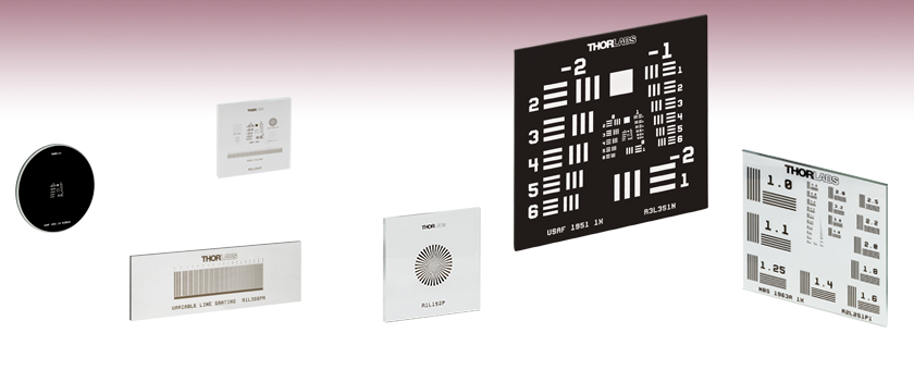
All of our resolution test target patterns are manufactured using photolithography and available as positive targets; and many have negative versions as well. We also offer several versions of high-contrast positive reflective targets. The positive targets consist of low-reflectivity, vacuum-sputtered chrome patterns plated on clear substrates and are useful for front-lit and general applications. The negative targets use low-reflectivity chrome to cover the substrates, leaving the patterns clear, and work well in back-lit and highly illuminated applications. The positive reflective targets are composed of a low-reflectivity chrome pattern etched on soda lime glass with a chrome background for high contrast in reflective applications. See the Graphs tab for spectral data of the materials used in these test targets.
In addition to our catalog test targets and reticles offered from stock, we can provide custom chrome patterns on soda lime, UV fused silica, or quartz substrates from 8 mm by 8 mm up to 85 mm by 85 mm. Substrates can be cut to shape for your application. Our photolithographic coating process allows us to create chrome features down to 1 µm. A few sample patterns are shown below, which can be made positive or negative, as shown in the image directly below.
Camera manufacturers sometimes list these equivalents because some photographers are more familiar with 35mm cameras and they want to make it easier to understand. It also gives us a standard of reference for all the different format sizes. They may also list the multiplier factor. For example, the APS-C multiplier is around 1.6x. So a 32mm lens on an APS-C camera (like the Nikon D3200) would act like a 50mm lens on a 35mm film camera. Does focusing affect the focal length?
Photolithographic Target Manufacturing Our extensive production capabilities enable us to provide solutions for imaging system calibration and measurements. We use contact photolithography with a mask aligner to define the pattern on the glass substrate. Once the pattern is defined, we chemically etch the substrates and clean them in a class 100 cleanroom.
Thorlabs offers positive and negative 1.5" x 1.5" (38.1 mm x 38.1 mm) resolution test targets that are made by plating low-reflectivity, vacuum sputtered chrome on a soda lime glass substrate. These targets have 8 groups (0 to +7) with 6 elements, offering a maximum resolution of 228.0 line pairs (one light line and one dark line) per millimeter. For more information on the 1951 USAF pattern, please see the Resolution Targets tab above.
To calculate the resolution at any given radial distance from the center of the sector star, start by calculating the thickness of a line pair, or one dark bar and one light bar, at that radius. This can be done using the formula for the chord length, given below, where r is the radial distance from the center. The angle Θ is the number of degrees covered by one pair of light and dark bars and is equal to 360° divided by the total number of bars. Once the thickness of the line pair is calculated, the resolution is the reciprocal of the thickness.
Learn how to use PhotoModeler with your camera to create detailed digital models: www.photomodeler.com/products/why.html
These resolution targets have a series of horizontal and vertical lines that are used to determine the resolution of an imaging system. A set of six elements (horizontal and vertical line pairs) are in one group, and ten groups compose the resolution chart. The image below shows Elements 2 and 3 of Group -2 on a resolution target.
The R2L2S4P positive target consists of a low-reflectivity chrome pattern plated on to a clear substrate and is useful for front-lit and general applications. Alternatively, the R2L2S4N negative target uses the same low-reflectivity chrome coating to cover the substrate, leaving the pattern itself clear, and works well in back-lit and highly illuminated applications.
Thorlabs offers two 3" x 1" positive variable line gratings with 18 sections of line grating with resolutions ranging from 1.25 line pairs (one light line and one dark line) per millimeter (lp/mm) to 250 lp/mm. The table below lists each of the available resolutions. The resolution of an optical system can be measured by determining the highest resolution grating with lines that the system is able to resolve.
Note: A technical photogrammetry term that you may come across is the “Principal Distance”. Strictly, the Principal Distance is the distance mentioned above (i.e. distance from imaging plane to the lens optical sensor), and the focal length is the principal distance when the lens is focused at infinity. See below for more information on focus vs focal length. When PhotoModeler lists focal length for a camera, it is actually the Principal Distance that is shown.
The spacing between the lines in each element is equal to the thickness of the line itself. When the target is imaged, the resolution of an imaging system can be determined by viewing the clarity of the horizontal and vertical lines. The largest set of non-distinguishable horizontal and vertical lines determines the resolving power of the imaging system. The chart below lists the number of line pairs per millimeter for a given element within a group based on the equation below. With our resolution targets, the maximum resolution is 228.0 line pairs per millimeter, which equates to roughly 4.4 µm per line pair. The 3" x 3" targets feature ten groups from -2 to +7; the 3" x 1" targets feature eight groups from 0 to +7; the 3" x 1" wheel pattern versions feature nine targets, each with six groups from +2 to +7; the 3" x 1" birefringent target features six group, from 0 to +5; the 1.5" x 1.5" targets feature eight groups from 0 to +7; the 1" x 1" targets feature eight groups from 0 to +7; the 18 mm x 18 mm (0.71" x 0.71") combined targets feature six groups from +2 to +7; the Ø1" targets feature either six groups, from +2 to +7, or eight groups, from 0 to +7; and the Ø1" wheel pattern versions feature six targets, each with six groups from +2 to +7.
Resolution test targets are typically used to measure the resolution of an imaging system. They consist of reference line patterns with well-defined thicknesses and spacings and are designed to be placed in the same plane as the object being imaged. By identifying the largest set of non-distinguishable lines, one determines the resolving power of a given system. Thorlabs offers resolution test targets with 1951 USAF, NBS 1952, and NBS 1963A patterns. Targets are also available with sector star (also known as Siemens star) patterns, Ronchi rulings, a variable line grating, or a combination of patterns for resolution and distortion testing. For more information on each pattern, see the Resolution Targets tab.
These resolution targets are offered in positive and negative versions. The R2L2S1P1 positive target consists of a low-reflectivity chrome pattern plated on to a clear substrate and is useful for front-lit and general applications. Alternatively, the R2L2S1N1 negative target uses the same low-reflectivity chrome coating to cover the substrate, leaving the pattern itself clear, and works well in back-lit and highly illuminated applications.
With line sets of three, these targets offer the advantage of an increased ability to recognize spurious resolution. Spurious resolution occurs when a set of lines is sufficiently blurred such that the overlap appears to form inverted, more distinct lines. This can cause a misreading of the resolution of the optical system, since it will appear that the lines are distinguishable. Spurious resolution also results in the appearance of one less line than exists in the line set. Since the difference between three lines and two is more easily noticed than the difference between five lines and four, for example, it is easier to recognize the occurrence of spurious resolution in targets with sets of only three lines.
Mounting These resolution test targets can be mounted in one of four of our microscopy slide holders. Our MAX3SLH Fixed Slide Holder provides two spring clips to mount the optic and can be mounted to any of our 3-axis translation stages. The MAX3SLH is only compatible with test targets greater than or equal to 2" wide and provides a clear aperture of 1", which may cover the chrome pattern on some of the test targets. Thorlabs also offers our XYF1(/M) Test Target Positioning Mount (see photo to the right) capable of translating a 1" to 3" wide rectangular target over a 50 mm x 30 mm area. The mount offers five 8-32 (M4) taps for six post-mountable orientations. The XYF1 uses nylon-tipped setscrews to secure the optic. Please note that the mount's support arms overlap the optic by 4.4 mm on each side. For users of the MLS203 Microscopy stage we offer the MLS203P2 Slide Holder for Inverted Microscopes, which can mount slides 25 mm to 26.5 mm wide and petri dishes 30 mm to 60 mm in diameter.
We do not suggest using a towel, rag, or wipe to dry the surface. If contamination persists, soak the reticle or target in a detergent and water solution for 1 hour, repeating as necessary.
Thorlabs offers positive and negative 3" x 3" (76.2 mm x 76.2 mm) resolution test targets that are made by plating low-reflectivity chrome on a soda lime glass substrate. The 3" x 3" targets have 10 groups (-2 to +7) with 6 elements per group, offering a maximum resolution of 228.0 line pairs (one light line and one dark line) per millimeter. For more information on the 1951 USAF pattern, please see the Resolution Targets tab above.
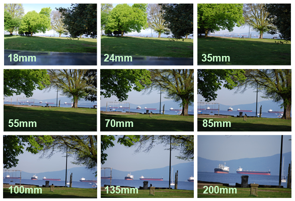
The focal length number tells us how much of the scene is captured in the picture. The lower the number the wider the view, and the more we can see. The higher the number, the narrower the view, and the less we can see. This is illustrated below – where the camera is stationary and the focal length (in white numerals) changes:
Thorlabs offers Ronchi ruling targets with resolutions ranging from 10 line pairs (one light line and one dark line) per millimeter (lp/mm) to 350 lp/mm. These square wave, constant-interval bar and space patterns are fabricated from the deposition of a dark low-reflectivity chrome pattern on a 3.00" x 1.00" x 0.06" (76.2 mm x 25.4 mm x 1.5 mm) soda lime glass substrate. This leaves a large 65 mm x 17 mm clear aperture, and works well in back-lit and highly illuminated applications. The dimensions of the glass substrate are the same as a standard microscope slide. These Ronchi rulings are excellent for evaluating resolution, field distortion, and parfocal stability in optical systems.
Thorlabs offers a birefringent 1" x 3" (25.4 mm x 76.2 mm) 1951 USAF resolution test target that is made by sandwiching a birefringent pattern between a soda lime glass slide and a Schott D 263®† M cover slip. The R3L1S1B target features eight groups (0 to 7) with six elements per group, offering a maximum resolution of 57.0 line pairs (one light line and one dark line) per millimeter. The test pattern is only observable if the target is placed between a pair of crossed polarizers, as shown in the image to the right. See the Resolution Targets tab above for more details on the test pattern.
Screenresolution test
Modern digital cameras can have imaging chips that are as small as 6mm by 4mm; some Smartphone cameras are even smaller, and then up to full 24mm by 35mm size. A very common size is the APS-C format at 16mm by 24mm. This smaller size affects what is considered to be a ‘normal’ focal length.
The pattern on this target is made from plating low-reflectivity, vacuum-sputtered chrome on a 0.06" (1.5 mm) thick soda lime glass substrate to achieve an optical density of ≥3.0 at 430 nm. The dark pattern and clear substrate are useful for front-lit and general applications.
The R1L3S5P positive 3" x 1" x 0.06" (76.2 mm x 25.4 mm x 1.5 mm) combined resolution / distortion test targets that are made by vacuum-sputtering low-reflectivity chrome with an optical density of ≥3 at 430 nm on a soda lime glass substrate. They are ideal for calibration of imaging systems and microscope stages. They are sized to fit in our MLS203P2 stage slide holder for use with our MLS203 microscope stages.


 Ms.Cici
 8618319014500