
What is polarization (wave polarization)? | Definition from ... - what is polarization
Tired of dealing with rubbery one-size-fits-none follow focus gears? Perhaps it’s time to level-up to custom-fit seamless follow focus gears.
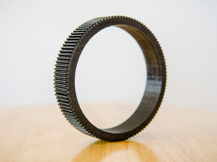
The gears are designed to cover as much of the focus ring as possible. This gives you more flexibility when positioning the follow focus on your rig. It also means that you are less likely to run into issues with the follow focus disengaging from lenses that extend as focus is adjusted.
Though there are several good reasons for rehousing still lenses for video work, it is an expensive endeavor. If all you really need is a solid gear to use your lenses with a follow focus, these seamless follow focus gears are a cost-effective and near-native solution.
The gear fit so closely to the lens barrel that I was afraid it was too tight and might damage the lens, but in fact, the fit was perfect. Once the gear slid over the focus ring’s rubber coating, it stayed put as if part of the lens.
Sean offers free revisions for anyone not happy with the fit, and after a few revisions, we had gears that fit perfectly for each lens. A set of spacer rings were even provided to help with finding the right fit for any lens.
The gears performed very well with standard follow focus units such as Zacuto’s Z-Drive and Fotga’s DP500II2. There were no issues with slippage or skipping, even during fast rack focusing with a speed crank.
Find lens focus ring sizecalculator
Also, the triangle formed by rays to the left of 0o is identical to the triangle formed by rays to the right of 0o but the angles R and L (Right and Left) would be the same only if the grating is perpendicular to the incident beam. This perpendicularity is inconvenient to achieve so, in practice, R and L are both measured and their average is used as in the grating equation. PROCEDURE Calibrating the Spectrometer Read and follow the procedures for calibrating the spectroscope found in the previous experiment. The calibration can be performed with the grating in place on the table. Measuring CAUTION: The diffraction grating is a photographic reproduction and should NOT be touched. The deeper recess in the holder is intended to protect it from damage. Therefore, the glass is on the shallow side of the holder and the grating is on the deep side. Place the grating on the center of the table with its scratches running vertically, and with the base material (glass) facing the light source. In this way, one can study diffraction without the complication of refraction (recall from the previous lab how light behaves when traveling through glass at other than normal incidence). Fix the grating in place using masking tape. Rotate the table to make the grating perpendicular to the incident beam by eye. This is not critical since the average of R and L accommodates a minor misalignment. Affirm maximum brightness for the straight through beam by adjusting the source-slit alignment. At this step, the slit should be narrow, perhaps a few times wider than the hairline. Search for the spectrum by moving the telescope to one side or the other. This spectrum should look much like that observed with the prism except that the order of the colors as you move away from zero degrees is reversed. Search for the second- and third-order spectra. Do not measure the higher-order angles, but record the order of colors away from zero degrees. For each of the seven colors in the mercury spectrum, measure the angles R and L to the nearest tenth of a degree by placing the hairline on the stationary side of the slit. Analysis Average the right and left angles for each color. Use the grating equation with d=(1/6000) cm to find the wavelength for each color. Remember that 108 angstrom = 1 cm. Calculate the percent deviation for each wavelength using % deviation = (data-theory)/theory x 100% where "theory" is the tabulated wavelength from the last experiment. Do not ignore the sign; it contains information. A positive % deviation means that the value is above the theory; a negative % deviation means that the value is below the theory. Do you notice any systematic problems in your seven % deviations? Use the grating equation with the tabulated values of from last time and your measured values of to calculate seven different values of N, the grating constant (N=1/d). Average the seven values of N. For the error on N, use the standard deviation on the mean (SDOM). Compare your answer to the accepted value of 6000 lines/cm. Does your value of N agree with the manufacturer's value within the error range? See Taylor page 5 if you are confused. What could be causing any discrepancy? Why is it necessary that the base side of the grating face toward the light source? Draw a ray diagram for the two cases: a) base toward the source (correct) and b) grating toward the source (incorrect). A certain color emerges at 15o in the first-order spectrum. At what angle would this same color emerge in the second order if the same source and grating are used? Don't forget your two random and two systematic error sources. Back to the Electricity and Magnetism Manual
These gears currently support a wide variety of lenses, but if you have a lens that is not already supported, you can send in measurements to get a custom gear made for the lens. This means that you can add a follow focus gear to virtually any lens.
LensFollowFocus Ring
With such a close fit, removing the gear from the lens’ rubber-coated focus ring does require a bit of pressure. By working the gear off slowly, it came off safely without leaving any marks on the lens.
Thus, the colors present in the light from the source incident on the grating would emerge each at a different angle since each has a different wavelength . Furthermore, a complete spectrum would be observed for n = 1 and another complete spectrum for n = 2, etc., but at larger angles. Also, the triangle formed by rays to the left of 0o is identical to the triangle formed by rays to the right of 0o but the angles R and L (Right and Left) would be the same only if the grating is perpendicular to the incident beam. This perpendicularity is inconvenient to achieve so, in practice, R and L are both measured and their average is used as in the grating equation. PROCEDURE Calibrating the Spectrometer Read and follow the procedures for calibrating the spectroscope found in the previous experiment. The calibration can be performed with the grating in place on the table. Measuring CAUTION: The diffraction grating is a photographic reproduction and should NOT be touched. The deeper recess in the holder is intended to protect it from damage. Therefore, the glass is on the shallow side of the holder and the grating is on the deep side. Place the grating on the center of the table with its scratches running vertically, and with the base material (glass) facing the light source. In this way, one can study diffraction without the complication of refraction (recall from the previous lab how light behaves when traveling through glass at other than normal incidence). Fix the grating in place using masking tape. Rotate the table to make the grating perpendicular to the incident beam by eye. This is not critical since the average of R and L accommodates a minor misalignment. Affirm maximum brightness for the straight through beam by adjusting the source-slit alignment. At this step, the slit should be narrow, perhaps a few times wider than the hairline. Search for the spectrum by moving the telescope to one side or the other. This spectrum should look much like that observed with the prism except that the order of the colors as you move away from zero degrees is reversed. Search for the second- and third-order spectra. Do not measure the higher-order angles, but record the order of colors away from zero degrees. For each of the seven colors in the mercury spectrum, measure the angles R and L to the nearest tenth of a degree by placing the hairline on the stationary side of the slit. Analysis Average the right and left angles for each color. Use the grating equation with d=(1/6000) cm to find the wavelength for each color. Remember that 108 angstrom = 1 cm. Calculate the percent deviation for each wavelength using % deviation = (data-theory)/theory x 100% where "theory" is the tabulated wavelength from the last experiment. Do not ignore the sign; it contains information. A positive % deviation means that the value is above the theory; a negative % deviation means that the value is below the theory. Do you notice any systematic problems in your seven % deviations? Use the grating equation with the tabulated values of from last time and your measured values of to calculate seven different values of N, the grating constant (N=1/d). Average the seven values of N. For the error on N, use the standard deviation on the mean (SDOM). Compare your answer to the accepted value of 6000 lines/cm. Does your value of N agree with the manufacturer's value within the error range? See Taylor page 5 if you are confused. What could be causing any discrepancy? Why is it necessary that the base side of the grating face toward the light source? Draw a ray diagram for the two cases: a) base toward the source (correct) and b) grating toward the source (incorrect). A certain color emerges at 15o in the first-order spectrum. At what angle would this same color emerge in the second order if the same source and grating are used? Don't forget your two random and two systematic error sources. Back to the Electricity and Magnetism Manual
Tilta SeamlessFocusGearRing
There are some great stills lenses, so I’ve been on the hunt for the perfect follow focus gears for a while. Then I discovered Sean McCurry’s custom-made follow focus gears. These gears appeared to meet all of my requirements– they were rigid, seamless, wide, and best of all each gear was tailor-made for a particular lens.
These focus gears stay put well enough that you could consider them a semi-permanent solution, but the nice thing is that they can be easily removed as well, so you’re not locked into particular way of using them. If you frequently shoot with a follow focus, you can safely leave the gears mounted on the lenses. Otherwise, you can keep the gears in a pocket and slide them on whenever the need arises.
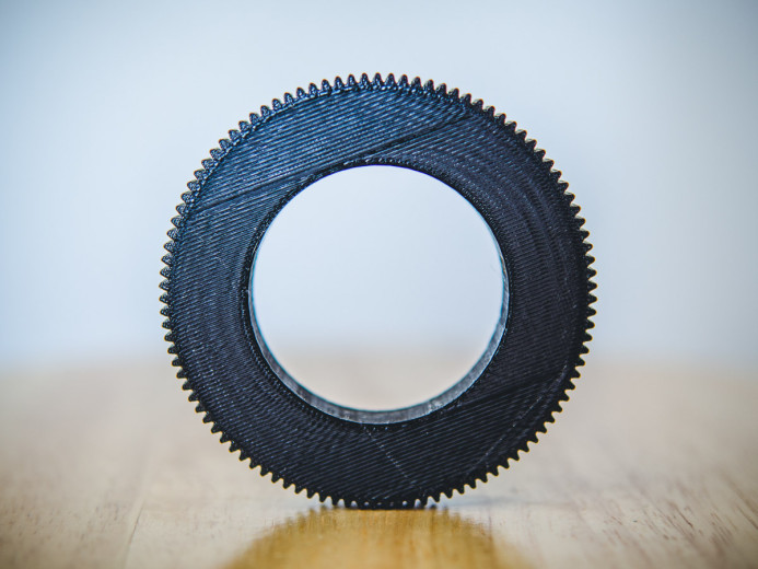
The plastic focus gears are lightweight (~18g) and do not add a significant amount of weight to the lens that could throw off your rig’s balance. Despite being lightweight, the gears are have proven to be quite solid and have not taken any damage in the field.
The follow focus gears are made out of plastic. The striations in the plastic are indicative of a 3D printing process, which explains how these gears can be custom designed to such precise tolerances.
Finally, you can also request a custom outer diameter for the gears. This allows you to keep the follow focus at the same distance from all of your lenses, saving you time when swapping lenses on set.
Consider two rays which emerge making an angle with the straight through line. Constructive interference (brightness) will occur if the difference in their two path lengths is an integral multiple of their wavelength () i.e., difference = n where n = 1, 2, 3, ... Now, a triangle is formed, as indicated in the diagram, for which n = d sin( ) and this is known as the DIFFRACTION GRATING EQUATION. In this formula is the angle of emergence (called deviation, D, for the prism) at which a wavelength will be bright, d is the distance between slits (note that d = 1 / N if N, called the grating constant, is the number of lines per unit length) and n is the "order number", a positive integer (n = 1, 2, 3, ...) representing the repetition of the spectrum. Thus, the colors present in the light from the source incident on the grating would emerge each at a different angle since each has a different wavelength . Furthermore, a complete spectrum would be observed for n = 1 and another complete spectrum for n = 2, etc., but at larger angles. Also, the triangle formed by rays to the left of 0o is identical to the triangle formed by rays to the right of 0o but the angles R and L (Right and Left) would be the same only if the grating is perpendicular to the incident beam. This perpendicularity is inconvenient to achieve so, in practice, R and L are both measured and their average is used as in the grating equation. PROCEDURE Calibrating the Spectrometer Read and follow the procedures for calibrating the spectroscope found in the previous experiment. The calibration can be performed with the grating in place on the table. Measuring CAUTION: The diffraction grating is a photographic reproduction and should NOT be touched. The deeper recess in the holder is intended to protect it from damage. Therefore, the glass is on the shallow side of the holder and the grating is on the deep side. Place the grating on the center of the table with its scratches running vertically, and with the base material (glass) facing the light source. In this way, one can study diffraction without the complication of refraction (recall from the previous lab how light behaves when traveling through glass at other than normal incidence). Fix the grating in place using masking tape. Rotate the table to make the grating perpendicular to the incident beam by eye. This is not critical since the average of R and L accommodates a minor misalignment. Affirm maximum brightness for the straight through beam by adjusting the source-slit alignment. At this step, the slit should be narrow, perhaps a few times wider than the hairline. Search for the spectrum by moving the telescope to one side or the other. This spectrum should look much like that observed with the prism except that the order of the colors as you move away from zero degrees is reversed. Search for the second- and third-order spectra. Do not measure the higher-order angles, but record the order of colors away from zero degrees. For each of the seven colors in the mercury spectrum, measure the angles R and L to the nearest tenth of a degree by placing the hairline on the stationary side of the slit. Analysis Average the right and left angles for each color. Use the grating equation with d=(1/6000) cm to find the wavelength for each color. Remember that 108 angstrom = 1 cm. Calculate the percent deviation for each wavelength using % deviation = (data-theory)/theory x 100% where "theory" is the tabulated wavelength from the last experiment. Do not ignore the sign; it contains information. A positive % deviation means that the value is above the theory; a negative % deviation means that the value is below the theory. Do you notice any systematic problems in your seven % deviations? Use the grating equation with the tabulated values of from last time and your measured values of to calculate seven different values of N, the grating constant (N=1/d). Average the seven values of N. For the error on N, use the standard deviation on the mean (SDOM). Compare your answer to the accepted value of 6000 lines/cm. Does your value of N agree with the manufacturer's value within the error range? See Taylor page 5 if you are confused. What could be causing any discrepancy? Why is it necessary that the base side of the grating face toward the light source? Draw a ray diagram for the two cases: a) base toward the source (correct) and b) grating toward the source (incorrect). A certain color emerges at 15o in the first-order spectrum. At what angle would this same color emerge in the second order if the same source and grating are used? Don't forget your two random and two systematic error sources. Back to the Electricity and Magnetism Manual
Sean sent over a few sample gears for us to test and we put them to work immediately. Simply put, these gears deliver. Read on for all the details.
Find lens focus ring sizenikon
From slow reveals to split-second focus racking, nothing beats a good follow focus unit when you need the ultimate control over your focus adjustments. However, in order to use a follow focus, your lenses need gears that allow the follow focus to turn the focus ring.
Camerafocus ring
As a result, the lens’ focus throw could even be over 360° of rotation, which means adjustable focus gears are unusable (due to the clamp on the gear). With these custom-made seamless focus gears, we can finally use a follow focus with native MFT glass.
The gears for the other lenses were custom-made based on measurements I had sent in. It turned out my measurements were a bit too tight and caused the focus rings to bind and skip a bit.
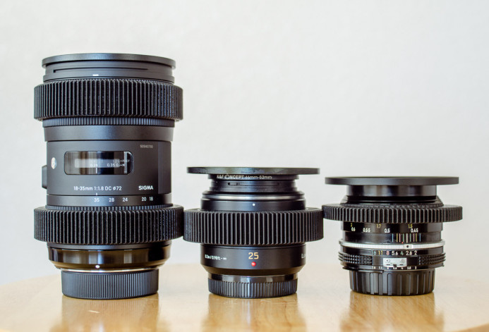
These seamless gears are particularly useful on native MFT lenses– such as Panasonic’s fast 25mm f/1.4 prime— which feature a unique style of fly-by-wire focus control. Not only do these lenses lack hard stops on the focus ring, but the amount of focus throw varies based on the speed at which the focus ring is turned.
Still photography lenses– which many shooters use on Panasonic GH4’s and Red Epics alike– do not have built-in follow focus gears, so we need to add gears to use a follow focus with these lenses.


 Ms.Cici
 8618319014500