
Front End Developer - hr front end
The advantages of both ruled and holographic gratings can be combined into the so-called blazed holographic gratings. The grooves on a blazed holographic grating are produced by applying a two-laser-beam-interference method, which is the same method used to produce conventional holographic gratings. Then, the ion-beam etching technique creates the standard “sawtooth” design that is used in conventional ruled gratings.
Bild 4: Schärfentiefe für unterschiedliche Abbildungsmaßstäbe und Blendenwerte, bei 20 µm Unschärfekreisdurchmesser.erschienen in: inVision ePaper | Objektive und Beleuchtungen
Ruled gratings are produced by physically forming a series of triangular grooves onto the surface of a substrate, using a diamond tool mounted on a ruling engine. The slope of the triangular groove is usually adjusted to improve the brightness of the grating at a specific wavelength. Once the triangular grooves have been formed, the substrate is coated with a highly reflective material, see Figure 3.

Sarspec uses regularly three types of gratings in its spectrometers depending on the purpose of the application and required specifications. A brief description of Ruled, Holographic, and Blazed Holographic grating can be found within the following sections.
Die maximal scharfe Abbildung entsteht nur in der Bildebene. Allerdings sind reale Objekte selten völlig flach. Es ist daher notwendig einen gewissen Tiefenraum abzubilden, in dem die Unschärfe einen Maximalwert nicht überschreitet. Für die Abbildung im Nahbereich ist diese Schärfentiefe direkt proportional zu Blendenzahl und dem Quadrat des Abbildungsmaßstabs. Für das oben genannte Beispiel mit 5 µm erforderlicher Auflösung, erzielt man bei einem Abbildungsmaßstab von 2, mit Blende 11 lediglich eine Schärfentiefe von 0,3 mm (Siehe Bild 4). Mit einem Abbildungsmaßstab von 1 und der Blendenzahl 8 erreicht man zwar nur 5,5 µm Auflösung, aber einen doppelt zu großen Schärfentiefebereich. Ein kleiner Verlust an Schärfe steht hier einem großen Gewinn an Tiefe gegenüber.
Um eine möglichst große Schärfentiefe zu erreichen, sind kleine Abbildungsmaßstäbe und entsprechend kleinerem Sensor günstig. Ein Objektiv mit großem Abbildungsmaßstab mit einem großen Sensor einfach nur abzublenden, führt nicht zum Erfolg.
Bild 3: Auflösung in der Objektebene für unterschiedliche Abbildungsmaßstäbe bei 550 nm Wellenlänge. Für 450 nm sind die Auflösungswerte mit 0,82; für 880 nm mit 1,6 zu multiplizieren.
Vielfach sind die erforderliche Auflösung und das Gesichtsfeld bereits vorgegeben. Gilt es beispielsweise eine Struktur von 5 µm noch kontrastreich darzustellen, muss deren Abbildung größer als die Grenzauflösung nach dem Rayleigh-Kriterium sein. Die Pixelauflösung des Sensors sollte dabei mindestens das Doppelte betragen. Für eine geläufige Pixelgröße von 3,45 µm muss die Struktur daher auf mindestens 7 µm, besser noch 10 µm abgebildet werden. Daher ist ein Abbildungsmaßstab von 2 erforderlich.
Because there is no need for mechanical ruling, the periodic structure errors found in conventional ruled grating are no longer present, and that ensures less amount of stray light and ghosting. Owing to their high efficiency and minimal stray light and ghosting, blazed holographic gratings are the ideal optical components to be used in instrumentation that require extreme efficiency and resolution and are included as standard in our UV/Vis, UV/Vis/NIR and Vis/NIR configurations.
Selbst bei einem Objektiv ohne Abbildungsfehler ist das Auflösungsvermögen durch die Beugung begrenzt. Ein Objektpunkt wird vom optischen System immer als Beugungsscheibchen, mit einem hellen Zentrum, umgeben von hellen und dunklen Interferenzringen, abgebildet. Dessen Radius in µm ergibt sich aus dem Produkt der Wellenlänge des abgestrahlten Lichts mal der Blendenzahl und dem Faktor 1,22. Sind zwei benachbarte Bildpunkte um den Radius dieses Airy-Scheibchens verschoben, fällt das helle Zentrum des einen Punktes gerade in das erste Minimum des anderen. Gemäß dem Rayleigh-Kriterium ist damit die Grenze „für die bequeme Beobachtung mit dem Auge“ erreicht. Neben einer möglichst kleinen Blendenzahl ist die Wellenlänge der Beleuchtung von entscheidender Bedeutung. Mit grünem Licht (550 nm) sind zwei benachbarte Punkte im Abstand von 5,4 µm gerade noch zu unterscheiden. Unter Verwendung von blauem Licht (450 nm) können sie sogar auf 4,4 µm zusammenrücken.
Die wichtigsten Größen der Bildverarbeitung sind ein gegensätzliches Paar. Einseitiges Maximieren führt hier nicht zum Erfolg. Das Jonglieren mit optischen Gesetzen ist gefragt.

The drawback of ruled diffraction gratings is that due to the nature of the production process, they have defects that can occur in the form of periodic errors, surface irregularities, or spacing errors. As a consequence of these defects, ruled gratings have increased stray light and ghosting effects.
The diffraction grating is the main element in the optical system of a spectrometer that separates incident polychromatic radiation (white light) into monochromatic radiation (light of one color). It consists of a series of parallel grooves, equally spaced and formed in a reflective coating deposited onto a glass substrate. The distance between each groove and the angles the grooves form with the substrate influence both the dispersion and efficiency of a grating.
Holographic gratings are produced by interfering with two laser beams to create a sinusoidal pattern on the surface of the substrate, then coating it with a highly reflective material, see Figure 4.
In der Bildverarbeitung ist oft beides notwendig: maximale Auflösung und perfekte Schärfentiefe. Aber leider arbeiten diese optischen Kerngrößen gegeneinander. Nur durch geschicktes balancieren mit Blende, Wellenlänge und Abbildungsmaßstab erreicht man für jede Aufgabe die bestmögliche Abbildung.
While ruled gratings offer higher efficiencies at a particular wavelength (blazed wavelength), they suffer from periodic errors in groove production, therefore generating high amounts of stray light. With holographic gratings, these errors are strongly reduced. The drawback of holographic gratings when compared to blazed gratings is reduced efficiency.
In ruled and ruled holographic gratings, changing the groove angle (the angle created by the longer side of the groove and the plane of the grating) moves the diffracted radiation along the spectral region and changes the blaze wavelength. When selecting the best grating for your spectrometer, take into consideration the grating efficiency – its maximum will, normally (also depending on the efficiency curve of the detector), correspond to the maximum sensitivity of the operational wavelength range (see Figure 2).
All spectrometers manufactured by Sarspec are equipped with fixed diffraction gratings that can be selected by the user according to the wavelength range of interest. The two key parameters when choosing the right grating for your spectrometer are the groove density which allows you to set the operational wavelength range and optical resolution and the grating groove efficiency for the selection of the wavelength range where your system sensitivity is at its maximum. Detailed information about these two parameters can be found in the following sections.
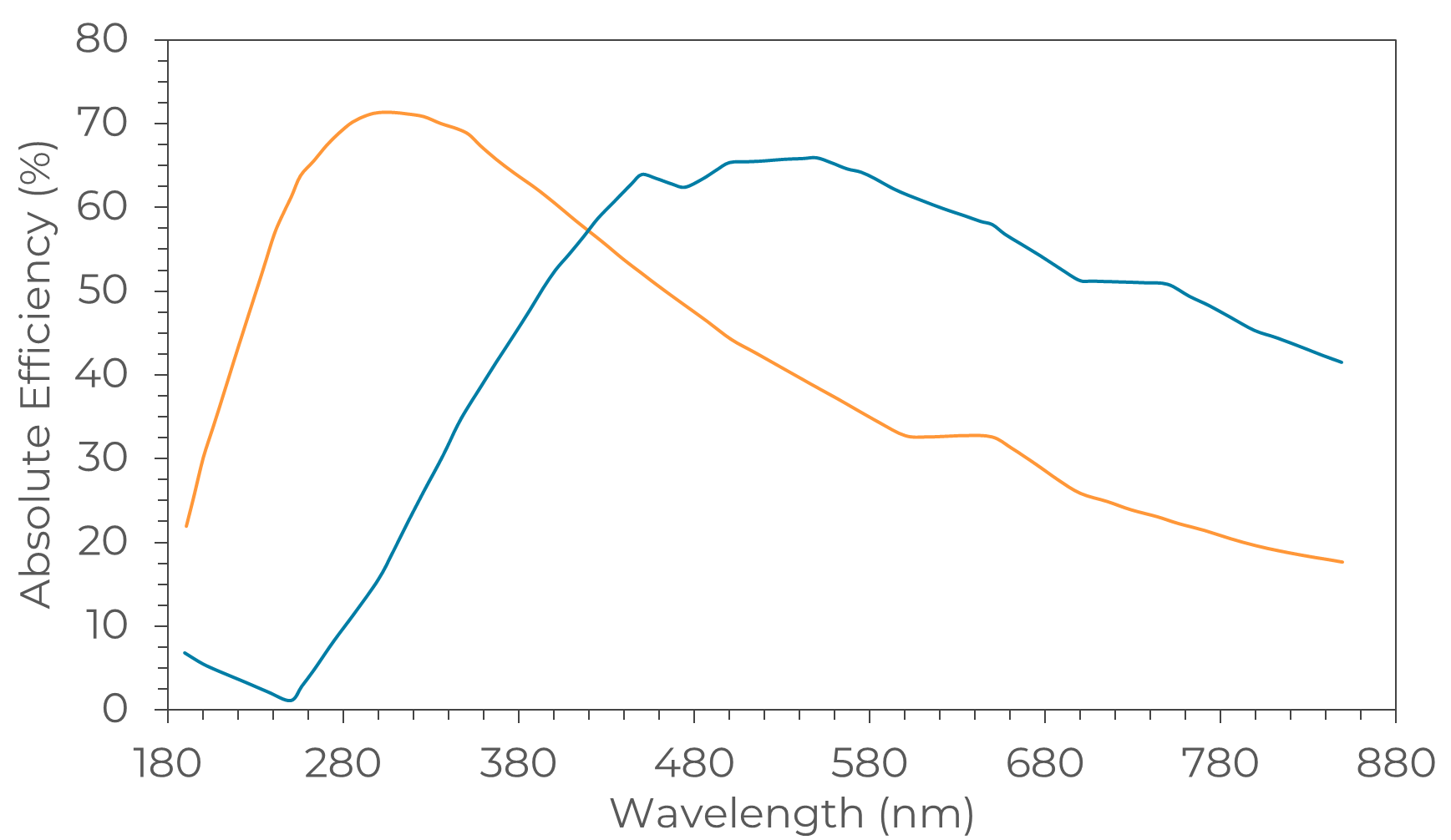
Figure 2 – Absolute efficiency curve of two 600 grooves/mm gratings, maximum efficiency peaks at 300 nm (orange) and 500 nm (blue).
The groove density or groove frequency is usually expressed in nm/mm and determines the range of wavelengths that are dispersed by the grating into the detector. The increase of the groove density (grooves (or lines)/mm) results in an improvement of the optical resolution for a certain slit width. On the other hand, groove density also defines the operational range of wavelengths of the grating, being that a higher groove density will generate shorter operational ranges for your spectrometer. Increasing the groove density leads to a higher optical resolution but also to a shorter wavelength operational range (see Figure 1).
Bild 2: Ist ein Objektpunkt um den Betrag a’ aus der Bildebene verschoben, entsteht ein Unschärfekreis u’. Die Größe der entstehenden Unschärfekreise u’1 und u’2 ist proportional zu den Blendendurchmessern D1 und D2.
Bild 1: Gemäß Rayleigh-Kriterium ist die Grenze der Auflösung erreicht, wenn bei benachbarten Bildpunkten Maximum und Minimum der Beleuchtungsstärken zusammenfallen.
As grating diffracts the incident radiation, it does not do so with uniform efficiency. The overall shape of the grating efficiency curve (a plot of absolute or relative diffracted efficiency as a function of the diffracted wavelength) shows normally a single maximum, at the peak of maximum brightness (or blaze wavelength) and is generally a rather complex function of wavelength and polarization of the incident radiation and depends on the groove density, plane of polarization, shape, and angle of the grooves and the reflectance of the coating material.


 Ms.Cici
 8618319014500