
What Is Infrared? - ir wavelength
Linepair resolution
For instance, if you are using See3CAM_CU135 – a 13 MP high-resolution USB camera from e-con Systems™ – to read barcodes, you need to make sure that the lens you pick can meet the maximum desired resolution.
lp/mm to pixel size
The resolving power of a lens is measured in line pair per millimeter or lp/mm. It is a measurement of spatial resolution used to calculate how small a detail in an image can be resolved by a lens. The unit expresses the number of line pairs you can fit within one millimeter.
The application photo to the right shows one possible fly's eye homogenizer configuration mounted in a 30 mm cage system. The light source is a PL201 compact laser module fixed in an AD11F SM1-threaded adapter held in a CP33(/M) cage plate. Alternatively, other light sources can be used such as a fiber-coupled LED connected to a collimator or mounted LED with a collimation adapter. The light passes through the first of two MLAs held in CP6T cage plates. These cage plates are thin enough to hold the mounted MLAs and secure them with a retaining ring while allowing the user to place the MLAs as close as possible to each other to maximize the rectangular output size. The lensed side of the first MLA should face the source. It is key to accurately align the rotation of the MLAs relative to each other; there will be artifacts on screen otherwise. The light then passes through an LB1471 N-BK7 bi-convex lens to produce a rectangular 9 mm x 12 mm area on an EDU-VS2(/M) screen, as seen in the photo to the right. A similar setup can be produced using our Fly's Eye Homogenizer devices as seen here.
In a camera system, the image sensor receives incident light (photons) – either focused through a lens or any other optics. Hence, lens selection plays a major role in determining image quality, FoV (Field of View), DoF (Depth of Field), etc.
Please note that the output rectangle is only sharply defined at a specific distance from the focusing lens. The actual size of the rectangle can be adjusted by changing the distance between the two MLAs. Decreasing the distance will increase the size of the rectangle and increasing the distance will make the rectangle smaller. Smaller rectangle sizes can also be produced by using lenses with shorter focal lengths. A simplified diagram of the setup is shown on the bottom right.
Vinoth Rajagopalan is an embedded vision expert with 15+ years of experience in product engineering management, R&D, and technical consultations. He has been responsible for many success stories in e-con Systems – from pre-sales and product conceptualization to launch and support. Having started his career as a software engineer, he currently leads a world-class team to handle major product development initiatives
lp/mm calculator
In the IMA test method – which is the automated method – the LW/PH value is calculated by considering the MTF30 value. This is an objective measurement of sharpness, which is better than the subjective analysis. The data in the IMA chart is in the units LW/PH, and it can be converted to lp/mm as shown in the above calculation.
For the mounted versions, the MLA is glued into a Ø1", 4.0 mm thick mount that is externally SM1-threaded (1.035"-40). The aperture of the lens window is 9.0 mm by 9.0 mm. The plate has slots that are compatible with a SPW602, SPW606, SPW801, or SPW909 spanner wrench. Their unmounted counterparts are most easily held using one of our cylindrical lens mounts, which are specifically designed to hold square or rectangular optics.
The reason why this is called the human eye perception method is that the number of lines counted may differ depending on the ability of the observer to distinguish between two consecutive lines.
The resolving power of a lens can be calculated manually as well as in automated manner. The manual method is called the human eye perception method, and the automated technique is called the IMA Test method. We will look at both these in detail in this section.
In today’s blog, let’s look at how to determine the resolving power of a lens, which is one of the most critical parameters to consider while choosing a lens for your application.
Image space resolution is inversely proportional to the sensor’s pixel size. This means the smaller the pixel size, higher will be the image space resolution value.
Line pairs per mmand pixel size
Image Space Resolution is the resolution in the image plane in consideration of the sensor pixel size. Generally, two pixels or one line pair is the highest frequency which can be resolved by a sensor – using the Nyquist frequency. Therefore, image space resolution is theoretically calculated as:
Line pairs per mmconverter
To understand how the theoretical and practical methods of calculating resolving power differ, we will look at how these are done for e-con Systems’ See3CAM_CU135 in the next section.
In this example, the setup was mounted using Ø1/2" posts and post holders that were secured to an MB3045(/M) breadboard using clamping forks.
Given below is the comparison of image space resolution and object space resolution values obtained using the theoretical and practical methods.
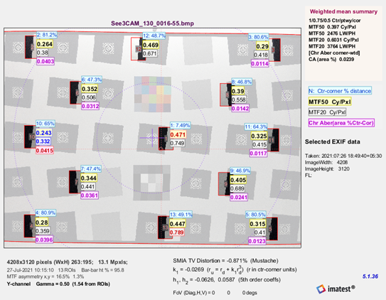
To give you an example, if the aspect ratio considered for See3CAM_CU135 – 13MP USB camera – is 4:3, the image of the resolution chart has to be captured at that aspect ratio to finally arrive at the resolving power. Below is a sample image of the resolution chart taken at an aspect ratio of 4:3.
For microlens arrays that are ideal for use in custom-built Shack-Hartmann wavefront sensors, please visit the Fused Silica Microlens Arrays page.
For instance, if you want to calculate the resolving power of See3CAM_CU135 – 4K USB camera – with the default product lens, you should capture the image of the resolution chart with the desired aspect ratio at the prescribed working distance.
lp/mm to resolution
Let’s say you have to decode an object like a small barcode and that too at a longer distance. You would have to differentiate the bars by allowing a certain amount of space between them. This minimum distance depends on the resolution of the camera. However, when you use a sensor with the desired resolution, it is also important to choose a lens that can help capture the level of detail expected from that resolution. This is where knowing the resolving capacity of the lens becomes important.
As mentioned above, Object Space Resolution denotes the resolving power of a lens. It defines the size elements of the object that can be resolved. It is calculated as:
There are multiple ways to homogenize the output of a light source. Microlens arrays (MLAs) used in a fly's eye homogenizer configuration transform a round collimated beam with a Gaussian profile into a rectangular homogeneous area. The size of the rectangle is defined by the size and pitch of the microlenses.
To calculate the resolving power or object space resolution value using the human eye perception method, you need to first find the LW/PH (line width per picture height) value. To do this, you must observe the line pair highlighted in red (horizontal or vertical) in the resolution chart given in the previous section (Figure 1).
Line pairs per mmradiology
Calculating the resolving power value of a camera lens practically involves taking into consideration the real aspect ratio of the camera.
These PMMA Microlens Arrays (MLAs) are available mounted or unmounted. MLAs are excellent for homogenizing and shaping light, yielding a flat top profile output or square spot patterns. PMMA has excellent UV resistance, filtering out UV light less than 300 nm. The microlenses have a plano-convex shape and are arranged in a 10.0 mm by 9.8 mm rectangular grid with a lens pitch of 1.0 mm by 1.4 mm. These can be used in fly's eye homogenizer configurations, where a round beam is transformed into a rectangular spot (see the Application tab for details). Alternatively, Thorlabs offers a line of Fly's Eye Homogenizer devices using these MLAs with 40 mm or 95 mm working distances.
Resolving power is calculated as object space resolution. And object space resolution is derived from what is called the image space resolution. We will now look at both the terms and learn now they are calculated.
A line pair is a pair of black and white lines next to each other with the same width and orientation. The ability to differentiate two bars as separate entities in a specific resolution would be based on the contrast level. It means that calculating resolution in terms of lp/mm is extremely useful when comparing lenses. This can act as one of the criteria while choosing the best-fit lens for a given sensor and application.
Please note that the Zemax file provided below is not the common sequential (SC) raytracing file which we typically provide, but the non-sequential (NSC) raytracing file. Be aware that the standard version of Zemax OpticStudio® does not support the NSC mode.
Using the above data, you can validate how much lp/mm a particular lens would resolve at a specific working distance. Based on this, you can select the right lens for your application. It is pertinent to note that a change in FoV will affect the magnification factor, which will end up affecting the practical image space resolution.
Use Microlens Arrays to transform a round collimated beam into a rectangular homogeneous spot.See the Application tab for details.
AR Coating OptionsWhile our uncoated PMMA microlens arrays offer excellent performance, improved transmission can be gained by choosing a lens with an antireflective coating on both sides to reduce the surface reflections. Our broadband antireflection (BBAR) coatings provide <0.8% average reflectance over one of the following wavelength ranges: 420 - 700 nm or 650 - 1050 nm.
Line pairs per mmcalculator
As shown in the chart, you can count the number until the line pair degrades. It is where you can’t distinguish the black and white lines (due to merge, grey colors will appear). Typically, the values of this line will be mentioned in the resolution chart (100 x per picture height).
If you are looking for help in selecting a camera solution with the best-fit lens for your application – no matter the industry, please write to us at camerasolutions@e-consystems.com. You can also visit our Camera Selector to get a full view of e-con Systems’ camera portfolio.


 Ms.Cici
 8618319014500