
What Is Focal Length? (And Why It Matters in Photography) - focal range explained
Confocalmicroscopy applications
Typical fluorescence microscopy involves illuminating the entire sample and detecting the resulting fluorescence. Illuminating and detecting from the entire sample includes collection of out-of-focus light above and below the focal plane, causing blurriness and image degradation. This effect is exacerbated when imaging 3D samples such as cells that contain liquid-filled areas that scatter light, causing information to be lost.
Confocalmicroscopy diagram
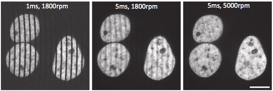
Figure 4: The effects of disk rotation speed and exposure time on the resultant image. From left to right, images show increasing exposure times and/or disk rotation speeds, which results in a cleaner image without streaks. Scale bar 10 µm.Image obtained from Stehbens et al. 2012.
Figure 3: Using a secondary micro-lens disk to improve lighttransmittance through the primary pinhole disk. Laser illumination is focused through the pinholes by the micro-lenses, with both disks spinning in sync over the sample.Image obtained from Graf et al. 2005.
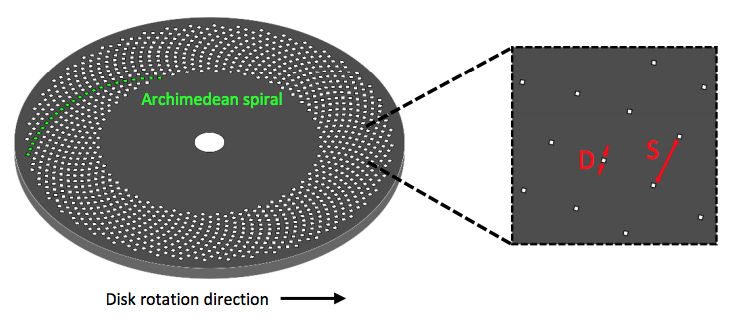
Figure 2: A standard Nipkow-Petran disk used in SDCMs. Hundreds of pinholes are arranged in Archimedeanspirals (left), which pass over the sample as the disk spins. The pinholes have diameter D and separation distance S, changing these values can optimize the resultant image received.
Confocalmicroscopy
Spinning disk confocal microscopy (SDCM) represents an alternative to LSCM. Rather than a single pinhole, a SDCM has hundreds of pinholes arranged in spirals on an opaque disk (figure 2), which rotates at high speeds. When spun, the pinholes scan across the sample in rows, building up an image. Using a spinning disk vastly improves the speed of image acquisition (allowing for imaging of fast dynamic processes and live specimens), and considerably reduces photo damage.
At the same time, with the continuous improvement of cylindrical lens processing technology, a mature and efficient processing technology has been formed, and its good quality reproducibility and repeatability are gradually recognized by the market. At present, the technology is gradually replacing the relatively backward traditional technology.
The main disadvantage of SDCM is that only a small proportion of light is transmitted through the disk to the sample, but with customizable pinhole disks, secondary micro-lens disks and highly sensitive cameras these limitations can be easily overcome, while also improving imaging speed and field of view even further to produce high resolution images faster than ever.
Spherical lenses are lenses taken out from a sphere such as a ball. Where as, cylindrical lenses are lenses taken out from a surface of a cylinder like a tumbler. Cylindrical lenses have an axis associated with them. Both, spherical and cylindrical power can keep changing through life.
This is the most wide use of cylindrical lens. Taking a plano concave cylindrical lens as an example, it can be a beam of collimated light that expands into a linear light source according to the magnification.
Such as line aggregation system, film camera system, fax machine and scanning imaging system of printing and typesetting, gastroscopy and laparoscopy in the medical field, vehicle video system in the automotive field with the participation of cylinder mirror. Also in linear detector lighting, barcode scanning, holographic lighting, light information processing, computer, laser emission. It is also widely used in strong laser system and synchrotron radiation beam line.
Optical cylindrical lens can be used for converging or diverging light beams in a single axis. Cylindrical lens is used in many industries and fields such as optical metrology, laser scanning, spectroscopy, laser diode output beam shaping, and light-sheet illumination microscopic imaging.
Optical Cylindrical Lens, mainly used to change the size of the imaging design requirements. Such as converting a spot to a line spot or changing the height of the image without changing the width of the image. Cylindrical lens has special optical properties. With the rapid development of high technology, cylindrical lens is used more and more widely.
Confocalmicroscopy ppt
How do confocal microscopes workphysics
A cylindrical lens is typically used to focus, condense or expand incoming light. A cylindrical lens has one cylindrical surface, causing light to be focussed in a single dimension or axis. It can also be used to expand the output of a laser diode into a symmetrical beam.
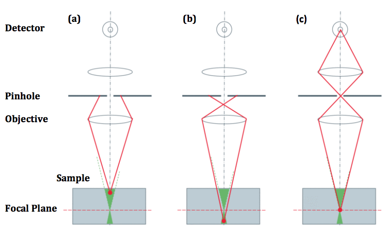
Confocal microscopy improves on standard fluorescence microscopy by using pinholes to reject out-of-focus light (figure 1), which results in greater resolution, greater contrast and reduced noise. However, this pinhole only images a tiny area of a sample (approx. 100 nm) and consequently needs to be scanned across the whole sample, which takes time and can cause photo damage. This format is known as laser scanning confocal microscopy (LSCM).
A cylindrical optical lens is typically used to focus, condense or expand incoming light. A cylindrical lens has one cylindrical surface, causing light to be focussed in a single dimension or axis. It can also be used to expand the output of a laser diode into a symmetrical beam. Cylinder lenses are technically more difficult to manufacture than spherical or flat lenses which is why Ecoptik uses state-of-the-art polishing techniques alongside stringent lens assessment to manufacture each lens.
Disadvantages ofconfocalmicroscopy
Confocalmicroscopy protocol
The cylindrical lens is also used for astigmatism. Collimation of diode output beam The output beam of the laser diode diverges in an asymmetrical form, and its collimation work is more challenging. For example, for a diode light source with a divergence angle, if only a standard spherical lens is used, it can only be collimated in a single direction, and divergence or convergence will occur in the other direction. Using cylindrical mirrors can decompose the problem into two one-dimensional directions. By combining two orthogonal cylindrical mirrors, the two directions can be collimated simultaneously.
According to the quantity of the customer's order and the requirements of the lens index, the appropriate processing technology is selected. There are two types of classical processing methods and high-polishing processing methods.
Confocalmicroscopy principle and working PDF
An important point to consider is that SDCMs excite/image multiple points at once and can spin at very high speeds, meaning that high-quality scientific cameras are needed in order to capture images from the sample. These cameras need to have high framerates due to the speed of the spinning disk, because longer exposure times or a slow disk rotation speed may result in a streaky image. By using cameras that can match high rotation speeds, high-quality images are produced, as seen in figure 4.
The pinholes in the disk are arranged so that every part of the image is scanned as the disk is spun. By altering the disk rotation speed, pinhole diameter and/or pinhole spacing; the image brightness, contrast and quality can be optimized, making SDCMs highly customizable. However, while larger pinhole diameters results in improved light transmittance through the disk it also reduces resolution, and while having big pinhole spacing eliminates any pinhole cross-talk, it also reduces light transmittance.
Having small pinholes with large spacing would result in higher resolution but the lowest transmittance of light through the disk. Transmittance can be improved with the addition of a second disk which contains micrometer-scale lenses in the place of pinholes. The micro-lens disk focuses light through each pinhole of the primary disk, with considerably improves light transmittance to the sample, as seen in figure 3.
SDCM offers a clear improvement on LSCM and conventional fluorescence microscopy, allowing for fast and efficient imaging of live samples, dynamic processes and optical sectioning of 3D samples in 2D slices. Multichannel images can be taken at multiple wavelengths, resulting in high-quality images dense with information, and deconvolution methods exist to further improve contrast and image quality.
A cylindrical optical lens is typically rectangular, square, or circular and of either a plano-convex or plano-concave design. The cylindrical optical lenses of Ecoptik combine low wedge with high surface accuracy. As a leading optical components manufacturer, we assess the quality of each individual lens using Trioptics centration measurement and a Zygo GPI interferometer. All Ecoptik lenses are available both uncoated or coated with a broad range of high durability, low loss AR coatings, and can be manufactured to 20-10 surface roughness.
Figure 1: Using a pinhole to block out-of-focus light. Light from above (a) or below (b) the focal plane is rejected bythe pinhole, while light from the focal plane (c) passes the pinhole to the detector. Image obtained from Leica Science Lab.


 Ms.Cici
 8618319014500