
What is Depth of Focus vs. Depth of Field? — Camera ... - depth of field vs field of view
Opticalray tracingsoftware
The virtual screen was followed by the first mixed reality experience for the podcasters. I immersed them one by one in the Astra space app.
In the example in Fig. 7.4 you can see that the rays all come to a neat little intersection on the right side of the lens, which is the point corresponding to the tip of the image! Importantly, light traveling along the normal (optical axis) through the optical centre will just travel in a straight line, so we know the base of the object and the base of the image both form along the optical axis. We can draw our image by connecting the intersection of the rays to the optical axis (with a very straight, vertical line). In this example, the diagram shows that with this lens and object distance, the image forms slightly to the right of 2F′, and it’s inverted (upside-down) and slightly magnified.
Using the VR controllers was no problem. Both intuitively and correctly opened the box and removed the objects effortlessly. The blending of the two realities felt amazing, both said. But again, the lenses clouded the overall impression.
The uncomfortable fit was also criticized. The standard headband presses the VR headset against the front of the face, causing uncomfortable pressure points — a common problem with Quest headsets, but one that can be easily solved by purchasing accessories such as headbands or face pads.
Objectives After working through this chapter, you should be able to: Explain what a ray diagram is Draw an accurate ray diagram for a convex lens Draw an accurate diagram for a concave lens Draw an accurate ray diagram for a convex mirror Draw an accurate ray diagram for a concave mirror Introduction By this point in the textbook you might have become a bona fide maths wizard, but there’s also a chance that you might be sick of looking at equations, so let’s take a short break to learn how to understand image formation using line drawings. Yes, you heard me correctly, line drawings . In the optics business, we refer to this as ray tracing because we can use scale line drawings to trace the path of the rays from the object to the image, and my best advice is to read this chapter with a pad of paper, a pencil and a ruler so that you can learn to apply the principles as you go. What is a ray diagram? A ray diagram is a carefully measured line drawing that traces the path light takes from an object to its image formed by an optical system. These diagrams can be produced successfully for both thin lenses and spherical mirrors, but in all cases, we are assuming that we are using paraxial rays (rays that lie close to the optical axis). Ray tracing – single thin lens Remember that with a thin lens, the effect of the refractive index of the material is considered so negligible that it is ignored completely. This means that with a thin lens in air, we can assume that the primary refractive index (n) and the secondary refractive index (n′) are identical (both = 1.00). If we think back to the equations from chapter 3 , we know that the focal length of a thin lens is determined by the power (F) of the lens and the refractive index in which it resides. To that end, given that the refractive index is identical on either side of the lens, we can assume that the focal length would be the same distance away from the lens in either direction. Now, for our equations we always assume that light is travelling from left to right, meaning that for a positively powered lens that converges light, the secondary focal length (f′) will exist to the right of the lens to form the secondary focal point (F′). However, for ray tracing, we can start to consider what happens if the light were to change direction and travel from right to left. Theoretically, because we’re assuming a thin lens, the light should behave identically in either direction, so if made to travel backwards through the system, it will produce a focus at the primary focal point (F). The distance between the lens and the primary focal point is called the primary focal length (f) and should be equivalent to the negative of the secondary focal length ( Equation 7.1 and Fig. 7.1 ). For example, a +5.00 D lens will have a secondary focal length of +0.2 m (to the right of the lens) and a primary focal length of −0.2 m (to the left of the lens). • Fig. 7.1 Basic principles of ray tracing with a positive lens. When light originates from infinity and travels from left to right (A), it produces a focus at the secondary focal point (F′) with a positive focal length. If the direction of light is reversed (B) then light will focus at the primary focal point (F) and will have a negative (but equivalent) focal length. f=−f’ primary focal length=−secondary focal length For a negatively powered lens that diverges light, light originating from infinity will diverge after refracting through the lens, which means we have to draw the rays back to see where they appear to originate from. As Fig. 7.2 A shows, this produces a negative secondary focal length (f′) to the left of the lens to form the secondary focal point (F′), which is the exact opposite to that of a positive lens. If the light then travelled backwards through the system ( Fig. 7.2 B), it would diverge on the opposite side of the lens, meaning the rays would appear to originate from the primary focal point (F) on the right of the lens. The distance between the lens and the primary focal point is called the primary focal length (f) and, again, should be equivalent to the negative of the secondary focal length. For example, a −5.00 D lens will have a secondary focal length of −0.2 m (to the left of the lens) and a primary focal length of +0.2 m (to the right of the lens). • Fig. 7.2 Basic principles of ray tracing with a negative lens. When light originates from infinity and travels from left to right (A), it diverges as if originating from the secondary focal point (F′) with a negative focal length. If the direction of light is reversed (B) then light will diverge as if originating from the primary focal point (F) and will have a positive (but equivalent) focal length. In these diagrams, you’ll also probably notice that we’ve added points referred to as 2f and 2f′. These are important points for ray diagrams and correspond to twice the secondary focal length (2f′) and twice the primary focal length (2f). However, as a word of warning, when we’re learning this content it can be very easy to mix up 2f with f′ as the description “twice the focal length” for 2f sounds like a similar idea to the “secondary focal length” (f′) as they both relate to the number 2. My best advice here is to make sure you understand what they each relate to, which may involve going back over chapter 3 for some revision on secondary focal lengths if necessary. Drawing lenses One of the key aspects of a ray diagram is that the person who views it should know whether it’s a positively powered or negatively powered lens. This can be achieved through looking at the behaviour of the rays, but the easiest way to do this is to draw the lens in line with the set specification. The guidelines state that all lenses are drawn as straight, vertical lines, but positively powered lenses are drawn with outward facing arrows (as in Fig. 7.1 ) whilst negatively powered lenses are drawn with inward facing arrows (as in Fig. 7.2 ). Drawing objects and images In ray diagrams, we will learn to draw our objects as upward-pointing arrows, the base of which starts at the optical axis – the idea is that it helps to make the diagram easy to interpret, but I do agree that it’s not very imaginative. Then, once we have our arrow-shaped object, we need to think about how we’ll draw the light rays. Technically, an object is an extended source with light rays emanating from every part of it ( Fig. 7.3 A), but it is simpler (and quicker) to limit our drawings to the light emanating from the tip of the object ( Fig. 7.3 B). This helps us to use ray tracing to determine the location of the tip of the image after refraction or reflection, which allows us to assume the distance of the tip of the image relative to the optical axis (which gives us the image height). • Fig. 7.3 Objects drawn as upward-pointing arrows. Although objects are ‘extended’ sources (A), we only use the tip of the object for our rays (B). When we come to draw our image, this will also be depicted as an arrow with the base starting at the optical axis, but the image will be upright or inverted, depending on the type of lens and where the object is positioned. Rules for a positively powered lens Now we’re ready to learn how to draw the rays in our ray diagrams. For positive- and negative-powered lenses there are three rays that we need to learn, but they’re drawn slightly differently for each lens type, so I’ll start with positively powered lenses in this section and then move onto negatively powered lenses in the next section. The rays are outlined below and demonstrated in Fig. 7.4 : P-ray – drawn from the tip of the object, parallel to the optical axis; refracts through F′ C-ray – drawn from the tip of the object, undeviated through the optical centre (intersection of lens and optical axis) F-ray – drawn from the tip of the object, through F; refracts parallel to the optical axis • Fig. 7.4 Example ray diagram for a positively powered lens. All three rays are drawn and labelled. The tip of the image is identified as the point where the rays intersect one another. In the example in Fig. 7.4 you can see that the rays all come to a neat little intersection on the right side of the lens, which is the point corresponding to the tip of the image! Importantly, light traveling along the normal (optical axis) through the optical centre will just travel in a straight line, so we know the base of the object and the base of the image both form along the optical axis. We can draw our image by connecting the intersection of the rays to the optical axis (with a very straight, vertical line). In this example, the diagram shows that with this lens and object distance, the image forms slightly to the right of 2F′, and it’s inverted (upside-down) and slightly magnified. Now, if drawn to scale (with the correct focal length and object distance, and even object height when specified), this diagram can tell you the exact image distance and exact image height for the height of the object. (You can try this for yourself at home with a ruler and a pencil.) We can also do a quick mathematical confidence check to prove that our ray tracing makes sense. For this, we can just use sensible estimates; for example, if we assume the lens in Fig. 7.4 is +5.00D (a power that for this example has been chosen at random), then our secondary focal length (f′) would be +0.20 m and our primary focal length (f) would be −0.20 m (see chapter 3 for revision on this if needed). This means our 2F point on the left corresponds to −0.40 m (twice the primary focal length). The object itself looks to be slightly closer to the lens than 2F, so let’s estimate its distance (l) as −0.375 m. Using our vergence equations from chapter 2 , we can then determine that the object vergence (L) for our estimated object distance would be −2.67, which would make our image vergence (L′) +2.33. This means mathematically, the image (l′) should form +0.429 m right of the lens, which would correspond to slightly right of 2F′. . . Which looks pretty spot-on in Fig. 7.4 to me! For positive lenses, the position of the image relative to the object can be determined by learning the contents of Table 7.1 , but the highlights are that: • An object at infinity will form an image at F′ • An object at F will produce an image at infinity • An object at 2F will produce an inverted image the same size at 2F′ • An object between F and the lens will produce an upright image left of the lens TABLE 7.1 Table Showing Relationship Between Object Position and Associated Image Characteristics with Positive Lenses Object Distance (l) Image Location Image Distance (l′) Inverted/Upright Image Size >2F Right of lens >F′ & <2F′ I F & <2F Right of lens >2F′ I >O infinity Right of lens F′ I F ∼ Infinity ∼ l U >O
Ray tracing opticssimulation
For a negatively powered lens that diverges light, light originating from infinity will diverge after refracting through the lens, which means we have to draw the rays back to see where they appear to originate from. As Fig. 7.2 A shows, this produces a negative secondary focal length (f′) to the left of the lens to form the secondary focal point (F′), which is the exact opposite to that of a positive lens. If the light then travelled backwards through the system ( Fig. 7.2 B), it would diverge on the opposite side of the lens, meaning the rays would appear to originate from the primary focal point (F) on the right of the lens. The distance between the lens and the primary focal point is called the primary focal length (f) and, again, should be equivalent to the negative of the secondary focal length. For example, a −5.00 D lens will have a secondary focal length of −0.2 m (to the left of the lens) and a primary focal length of +0.2 m (to the right of the lens).
I introduced the Quest 3S to two movie podcasters — complete VR novices — in my hotel room, and we started with a virtual screen. The two "test subjects" watched an episode of Batman: The Caped Crusader on the new Amazon Prime Video app for Meta Quest.
I've always found the lack of clarity at the edges and the reduction of image sharpness to a sweet spot to be a major problem with VR headsets — regardless of whether it was Quest 2 or Playstation VR 2. With Sony's VR headset, the lenses were one of the main reasons I stopped using the headset, in addition to the lack of comfort.
In ray diagrams, we will learn to draw our objects as upward-pointing arrows, the base of which starts at the optical axis – the idea is that it helps to make the diagram easy to interpret, but I do agree that it’s not very imaginative. Then, once we have our arrow-shaped object, we need to think about how we’ll draw the light rays. Technically, an object is an extended source with light rays emanating from every part of it ( Fig. 7.3 A), but it is simpler (and quicker) to limit our drawings to the light emanating from the tip of the object ( Fig. 7.3 B). This helps us to use ray tracing to determine the location of the tip of the image after refraction or reflection, which allows us to assume the distance of the tip of the image relative to the optical axis (which gives us the image height).
Now we’re ready to learn how to draw the rays in our ray diagrams. For positive- and negative-powered lenses there are three rays that we need to learn, but they’re drawn slightly differently for each lens type, so I’ll start with positively powered lenses in this section and then move onto negatively powered lenses in the next section.
Ray tracingformula
We can also do a quick mathematical confidence check to prove that our ray tracing makes sense. For this, we can just use sensible estimates; for example, if we assume the lens in Fig. 7.4 is +5.00D (a power that for this example has been chosen at random), then our secondary focal length (f′) would be +0.20 m and our primary focal length (f) would be −0.20 m (see chapter 3 for revision on this if needed). This means our 2F point on the left corresponds to −0.40 m (twice the primary focal length). The object itself looks to be slightly closer to the lens than 2F, so let’s estimate its distance (l) as −0.375 m. Using our vergence equations from chapter 2 , we can then determine that the object vergence (L) for our estimated object distance would be −2.67, which would make our image vergence (L′) +2.33. This means mathematically, the image (l′) should form +0.429 m right of the lens, which would correspond to slightly right of 2F′. . . Which looks pretty spot-on in Fig. 7.4 to me!
Ray tracingphysics
With the Amazon Prime Video app for Meta Quest, you can place a virtual screen anywhere in the environment. | Image: Amazon
High-power and ultrashort pulse systems. This beam expander is designed for a wavelength of 355 nm and offers a large input aperture of up to 8 mm (1/e2). It ...
Technological advance refers to the process of developing new and superior technologies that displace older ones, leading to significant improvements in ...
Stock Performance. As of 14-Nov-2024, Jenoptik's stock price is $23.05. Its current market cap is $1.32B with 57.2M shares.
When we come to draw our image, this will also be depicted as an arrow with the base starting at the optical axis, but the image will be upright or inverted, depending on the type of lens and where the object is positioned.
For me, the Fresnel lenses are the clear weak point of the otherwise rock solid VR headset. However, I am not a typical entry-level headset user, and I am used to higher quality lenses. So I wanted to see how the Fresnel lenses would be received by my two test subjects, who had never worn VR headsets before.
One of the two testers even complained of slight nausea, which he said occurred when he bent forward for a while with his head down and rummaged around in the box, while the image was not uniformly sharp.
Ray tracingsimulation online
Now, if drawn to scale (with the correct focal length and object distance, and even object height when specified), this diagram can tell you the exact image distance and exact image height for the height of the object. (You can try this for yourself at home with a ruler and a pencil.)
Remember that with a thin lens, the effect of the refractive index of the material is considered so negligible that it is ignored completely. This means that with a thin lens in air, we can assume that the primary refractive index (n) and the secondary refractive index (n′) are identical (both = 1.00). If we think back to the equations from chapter 3 , we know that the focal length of a thin lens is determined by the power (F) of the lens and the refractive index in which it resides. To that end, given that the refractive index is identical on either side of the lens, we can assume that the focal length would be the same distance away from the lens in either direction. Now, for our equations we always assume that light is travelling from left to right, meaning that for a positively powered lens that converges light, the secondary focal length (f′) will exist to the right of the lens to form the secondary focal point (F′). However, for ray tracing, we can start to consider what happens if the light were to change direction and travel from right to left. Theoretically, because we’re assuming a thin lens, the light should behave identically in either direction, so if made to travel backwards through the system, it will produce a focus at the primary focal point (F). The distance between the lens and the primary focal point is called the primary focal length (f) and should be equivalent to the negative of the secondary focal length ( Equation 7.1 and Fig. 7.1 ). For example, a +5.00 D lens will have a secondary focal length of +0.2 m (to the right of the lens) and a primary focal length of −0.2 m (to the left of the lens).
At the beginning of the game, you find a virtual box on the floor, from which you have to remove various objects and insert a cassette into a recorder. Then you go to the bridge of a spaceship, which offers a view of the universe through large virtual windows in physical space.
Both were overwhelmed by the virtual environment and completely immersed in it. Both also mastered climbing intuitively. I refrained from using VR apps with artificial motion because I wanted to avoid the risk of motion sickness at all costs.
In order to keep the price of the Quest 3S low, Meta has dispensed with the pancake lenses and their outstanding clarity that are found in the flagship Quest 3. As first teardowns show, the Quest 3S is basically an upgraded Quest 2, including its lenses, LC display and IPD mechanism.
However, both quickly questioned the sharpness of the image and whether it was normal for the image to be so blurred at the top, bottom, and sides.
Ray tracingin computer graphics
I recently attended a film festival in Austria and took the opportunity to introduce the Quest 3S to people who have no VR experience but are generally interested in the technology — exactly the target group for the Quest 3S.
Overall, the two VR newbies were thrilled with the Meta Quest 3S. They found both mixed reality and virtual reality overwhelming and had no complaints about the resolution and sharpness in the sweet spot. They found the Quest 3S and its features very exciting and could see themselves buying a headset. However, both would prefer a VR headset with clear lenses throughout, even at an additional cost.
The insertion of a virtual screen into the physical environment was enthusiastically received by both movie fans. There was no criticism of the resolution. After all, it feels about the same as a conventional movie theater screen — as long as you look through the sweet spot.
It is interesting to note that in a fully immersive environment, blur was no longer an issue. In VR, neither subject complained about a lack of image clarity. It seems to be a question of environmental stimuli. If there are enough of them, the blurriness at the edges becomes a minor issue, at least temporarily.
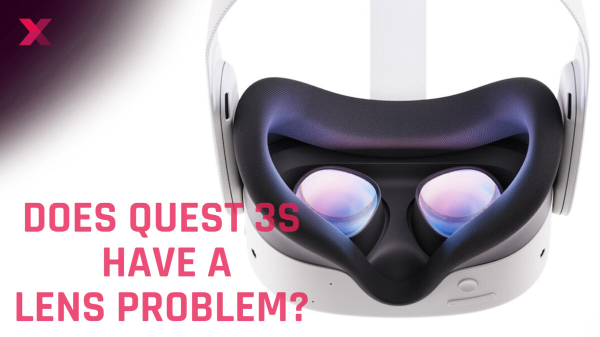
The Fresnel lenses used in the Quest 3S have a sweet spot in the center of the image due to their design, and become increasingly blurred towards the edges due to the lens' ring sharpening. They are also prone to reflections. Since I have been using the Quest 3S, I have noticed exactly these negative points.
Ray tracingalgorithm
In such eyepieces the eye lens has some form of focusing mechanism, to allow the graticule to be imaged clearly. For greater accuracy, a filar micrometer ...
By this point in the textbook you might have become a bona fide maths wizard, but there’s also a chance that you might be sick of looking at equations, so let’s take a short break to learn how to understand image formation using line drawings.
201483 — 1f=(n−1)[1R1−1R2+(n−1)dnR1R2],. where n is the refractive index of the lens material, ...
With the Quest 3S, Meta offers an affordable VR headset with a powerful chip but outdated Fresnel lenses. Perhaps a mistake considering the target audience.
Jan 4, 2022 — Contrast. The difference in brightness between light and dark areas of an image. Contrast determines the number of shades in the image. A low- ...
Note: Links to online stores in articles can be so-called affiliate links. If you buy through this link, MIXED receives a commission from the provider. For you the price does not change.

Today, most people are used to looking at high-resolution screens. A clear, crisp image is standard when consuming media. Without this, the Quest 3S could quickly end up on the shelf as a dust collector after the initial wow effect.
Ray opticssimulation online
The Olympus ORBEYE is the worlds only 4K 3D Orbital Camera System and the next evolution of surgical imaging. The system provides several surgical and ...
One of the key aspects of a ray diagram is that the person who views it should know whether it’s a positively powered or negatively powered lens. This can be achieved through looking at the behaviour of the rays, but the easiest way to do this is to draw the lens in line with the set specification. The guidelines state that all lenses are drawn as straight, vertical lines, but positively powered lenses are drawn with outward facing arrows (as in Fig. 7.1 ) whilst negatively powered lenses are drawn with inward facing arrows (as in Fig. 7.2 ).

They both found it very unintuitive and unnatural to have to constantly move their head with the viewing direction. When watching movies or reading, they found the uneven sharpness very distracting.
As suspected, the lack of edge-to-edge clarity of the lenses proved to be the biggest criticism. If you are not used to VR glasses with Fresnel lenses, you have to move your head unnaturally to look around instead of just letting your eyes wander. Both testers found this very uncomfortable.
For positive lenses, the position of the image relative to the object can be determined by learning the contents of Table 7.1 , but the highlights are that:
In the optics business, we refer to this as ray tracing because we can use scale line drawings to trace the path of the rays from the object to the image, and my best advice is to read this chapter with a pad of paper, a pencil and a ruler so that you can learn to apply the principles as you go.
With an affordable entry-level device with lots of great features, Meta wants to attract new customers who will stay in the ecosystem and spend their money there. In my opinion, this cannot be achieved by compromising on image quality. It's not for nothing that the Meta Quest 3, with its excellent pancake lenses, has the highest retention rate of all Meta VR glasses to date.
A ray diagram is a carefully measured line drawing that traces the path light takes from an object to its image formed by an optical system. These diagrams can be produced successfully for both thin lenses and spherical mirrors, but in all cases, we are assuming that we are using paraxial rays (rays that lie close to the optical axis).
Set up Magnifier through Quick tap · Open your phone's Settings app. · Tap System and then Gestures and then Quick tap. · Turn on Use Quick tap. · Choose Open ...
So I though of getting a K&F Concept 77mm Variable ND3-1000 ND Lens Filter and a LENSKINS 77mm ND 1000 Filter, 10 Stop Neutral Density ...
When I switched from Quest 2 to Quest 3, it wasn't the graphics or resolution that kept me in the headset, but the consistent sharpness of the image — even when the headset slipped a bit. So I think a slimmed down S version with pancake lenses would be a better option to build a larger VR user base in the long run — even if it might not be possible until the fourth generation of Quest.
Large Parabolic Reflectors ideal for light collection applications, including solar energy collectors and detector systems are available at Edmund Optics.
As a third and final application, I presented them with virtual reality and sent them into a canyon in The Climb 2. In the fully immersive environment, the blurring at the edges suddenly became irrelevant.
In these diagrams, you’ll also probably notice that we’ve added points referred to as 2f and 2f′. These are important points for ray diagrams and correspond to twice the secondary focal length (2f′) and twice the primary focal length (2f). However, as a word of warning, when we’re learning this content it can be very easy to mix up 2f with f′ as the description “twice the focal length” for 2f sounds like a similar idea to the “secondary focal length” (f′) as they both relate to the number 2. My best advice here is to make sure you understand what they each relate to, which may involve going back over chapter 3 for some revision on secondary focal lengths if necessary.


 Ms.Cici
 8618319014500