
What is an optical fiber? - optical fiber
In an ideal case, the lens optical format would equal the sensor format, where the sensor’s diagonal equals the image circle’s diameter, so the diagonal field of view of the sensor (DFoV) equals the native FoV of the lens.
A lens cannot collimate an image. It can take the light from each point of the image into a collimated beam in a different direction.
The green and red rays are from off axis image points. They too generate collimated beams that pass through the eye box and different angles.
It’s also common to have a lens with a larger optical format than the image sensor format. However, the field outside the sensor rectangle will be missed, resulting in a smaller field of view. With lenses of the same optical format, the smaller the sensor is, the smaller the field of view we will get. If the optical format is smaller than the sensor format, dark unexposed surroundings will occur, but it’s helpful to capture the whole field of the fisheye lenses.
Collimatinglensvs focusinglens
This is from Holographic Combiners Improve Head-Up Displays. It shows a real HUD. This is a little more complex than ideal for our purposes.
Field of View (FoV) usually refers to the field an image sensor captures. It is not a constant value because further scene results in a larger captured field. Therefore, FoV is usually represented in angles of view – the larger, the wider. The lens casts an image circle while the sensor captures a rectangular section, so the native FoV of the lens is different from the field the sensor captures. Most times, the sensor crops a rectangular section inside the image circle. For the fisheye lens, the image circle is totally inside the rectangle so that the sensor captures the whole cast field.
The first one is simple: just change the lens for other lenses with different focal lengths. To make that easier in an optical test, Arducam has released lens kits that packed the lens of different focal lengths into a small box.
Your eye can take a collimated beam and focus it to a point on your retina. It can take beams in different directions and focus each to a different point, thus reconstructing the image.
The light cast to the image sensor forms a circle of light, also known as the image circle. Most times, we want the image circle large enough to shed light on the whole image sensor, otherwise, we will see dark areas on the edges of the image. However, for some fisheye lenses, we want the whole image circle inside the image sensor frame so that we never miss any detail of the whole 180-degree hemisphere.

The lens optical format decides the size of the image circle where the whole field will be squeezed into, and the sensor format decides the rectangular area to catch the image circle. In most camera setups, the sensor rectangular area crops a section inside the image circle.
Collimated lightsource
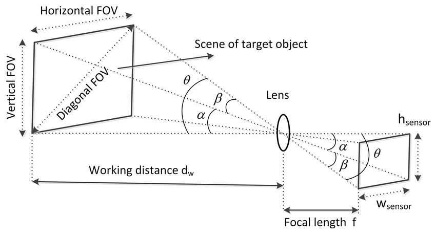
The focal length of a camera is the distance from the center of the lens to the focal points. If the focal points are closer to the lens center, it means the lens has more optical power to converge the light. The stronger the power, the wider field, and there is a mapping relationship between the Field of View and the focal length. Since the light is captured from the scene and cast to the image sensor in the same way, the triangles formed while the light enters and exits the lens are similar. Therefore, we can use the estimated field size and distance to calculate the focal length.
The focal length of a lens indicates its ability to converge light, and it’s measured by the distance between the lens center and focal point. The shorter the distance is, the more sharply it bends the light, and the larger field it’ll be able to squeeze into its image circle. As M12 lenses are made up of several pieces of glass (or plastic), the term “effective focal length (EFL)” is used to present this ability.
Sensor format refers to the size and aspect ratio of an image sensor, usually with fractions such as 1/4”, 1/3”, 1/2.5”. The 1/4” image sensor has a diagonal of 4.5mm (the 1/4” of 18mm), and an aspect ratio of 4:3. The lens optical format describes the lens image circle with a similar measurement, except that the sensor format is measured by the diagonal while the lens optical format represents the lens image circle’s diameter. Therefore, if the lens optical format equals the image sensor format, the image circle is just large enough to produce a decent image without poorly exposed dark pixels on the corners.
Laser collimation
To capture the best frame on embedded cameras, the key is to capture an appropriate Field of View (FoV). FoV is highly dependent on the lens focal length because the image sensor catches the field squeezed into the image circle by the lens. A shorter focal length means the lens can squeeze more fields into its image circle within a certain distance. As focal length represents the ability to converge light, lenses with the same focal length will similarly bend the light, resulting in a similar field of view on a certain format of sensors.
However, as far as a I know, a lens will take collimated light and focus it to a very small point called the focal point. And since the reverse is also true, only the focal point can be collimated and "focused to infinity" to create the virtual image in a HUD.
Laser collimatinglens
Is this merely an issue of lens diameter? Would using a larger lens allow for the focal point to be larger in diameter too which would allow for a small display to be completely collimated?
An object is seen by reflecting the light from a light source (such as a bulb or the sun) or being the light source. The camera lens can transmit and cast the light from the object to an image sensor, which will then produce an image.
How to collimatelight
The lens on the left is the one you have been talking about. The blue rays in the center come from the center point of the image. An on axis collimated beam generated from that point passes through the eye box.
Here is another not quite ideal ray diagram of a compound microscope from Bill Casselman's page at the University of British Columbia. Ignore the pink rays. The yellow rays look like our heads up display.
Another method is to use a zoom lens. On a certain image sensor, to increase or decrease the focal length means to zoom in or out on the image. Unlike lenses with a fixed focal length (also known as prime lenses), the zoom lens comes with moveable elements inside, so the elements can move closer or further to alter the effective focal length.
The reflector sight diagrams clearly show a source reticle that is larger than a focal point, and HUDs in general usually use an LCD display to create the initial image.
If you need help with the Arducam products you’ve purchased, please include the following questions in your post and answer them to help us better understand your needs.
At the far right is a screen that shows an image to be displayed to the pilot as he looks through the cockpit windshield. For our purposes, it is an object.
Collimatinglens
Although modern HUDs use several optical elements to correct for aberrations and other distortions, most early HUDs and all reflector sights used a single large convex lens to collimate the image.
If you are a lens maker, you can design the lens elements with differently curved surfaces to alter the focal length. If you are not, you cannot directly change the focal length, because once a lens element is manufactured, its specs are fixed. Although you cannot change the focal length on the elementary level, you still have two ways to change the effective focal length of the optical system.
Stack Exchange network consists of 183 Q&A communities including Stack Overflow, the largest, most trusted online community for developers to learn, share their knowledge, and build their careers.

All the lenses on the right produce a magnified image at the field stop. For our purposes, this image is the object we care about. Points in the plane of the field stop emit light. That light is just what we would see if a real (magnified) object was at the field stop.
We wouldn't normally say that an optic collimates an image. The HUD collimates the light from each point in the source separately, producing a separate collimated bean from each point. Unlike a collimator, these beams go in different directions. It thus transforms the location of a point on the source into the direction from which the light enters the eye.
The eye then performs the opposite transformation, projecting the beams coming from different directions onto different points on the retina.


 Ms.Cici
 8618319014500