
What IR-Pass Filter Do You Use, 685nm or 742nm? - ir pass filter
When a gaussian beam propagates through a thin lens, the outgoing beam is also a (different) gaussian beam, provided that the beam travels along the cylindrical symmetry axis of the lens, and that the lens is larger than the width of the beam. The focal length of the lens f {\displaystyle f} , the beam waist radius w 0 {\displaystyle w_{0}} , and beam waist position z 0 {\displaystyle z_{0}} of the incoming beam can be used to determine the beam waist radius w 0 ′ {\displaystyle w_{0}'} and position z 0 ′ {\displaystyle z_{0}'} of the outgoing beam.
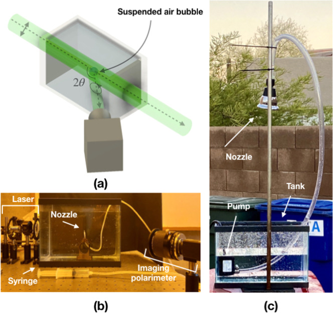
Three different light sources with different DoLP are used in this study. One source is the diode laser, which emits light of linear polarization. Another source is natural skylight, which is partially linearly polarized with maximum theoretical DoLP ≈ 0.75–0.80, caused by single Rayleigh scattering26,27. The third source is a fluorescent lamp, which outputs unpolarized light and serves as a comparison to linearly polarized sources. The DoLP of the sources ranges from unity (diode laser), to 0.70 (natural skylight), down to 0 (fluorescent light). The indoor experimental setup is shown in Fig. 2(a,b). The outdoor experimental setup is shown in Fig. 2(c). An imaging polarimeter is utilized to measure the scattered light in both setups.
The Gouy phase results in an increase in the apparent wavelength near the waist (z ≈ 0). Thus the phase velocity in that region formally exceeds the speed of light. That paradoxical behavior must be understood as a near-field phenomenon where the departure from the phase velocity of light (as would apply exactly to a plane wave) is very small except in the case of a beam with large numerical aperture, in which case the wavefronts' curvature (see previous section) changes substantially over the distance of a single wavelength. In all cases the wave equation is satisfied at every position.
Fundamentally, the Gaussian is a solution of the axial Helmholtz equation, the wave equation for an electromagnetic field. Although there exist other solutions, the Gaussian families of solutions are useful for problems involving compact beams.
where Lpl are the generalized Laguerre polynomials. CLGlp is a required normalization constant:[22] C l p L G = 2 p ! π ( p + | l | ) ! ⇒ ∫ 0 2 π d ϕ ∫ 0 ∞ d r r | u ( r , ϕ , z ) | 2 = 1 , {\displaystyle C_{lp}^{LG}={\sqrt {\frac {2p!}{\pi (p+|l|)!}}}\Rightarrow \int _{0}^{2\pi }d\phi \int _{0}^{\infty }dr\;r\,|u(r,\phi ,z)|^{2}=1,} .
Outdoor images of an irregular shaped water drop illuminated by polarized skylight coming out of a nozzle are shown. High |DoCP| is recorded. Magnified views show details of the water drop.
Secure .gov websites use HTTPS A lock ( Lock Locked padlock icon ) or https:// means you've safely connected to the .gov website. Share sensitive information only on official, secure websites.
I ( r , z ) = | E ( r , z ) | 2 2 η = I 0 ( w 0 w ( z ) ) 2 exp ( − 2 r 2 w ( z ) 2 ) , {\displaystyle I(r,z)={|E(r,z)|^{2} \over 2\eta }=I_{0}\left({\frac {w_{0}}{w(z)}}\right)^{2}\exp \left({\frac {-2r^{2}}{w(z)^{2}}}\right),}
Arbitrary solutions of the paraxial Helmholtz equation can be decomposed as the sum of Hermite–Gaussian modes (whose amplitude profiles are separable in x and y using Cartesian coordinates), Laguerre–Gaussian modes (whose amplitude profiles are separable in r and θ using cylindrical coordinates) or similarly as combinations of Ince–Gaussian modes (whose amplitude profiles are separable in ξ and η using elliptical coordinates).[5][6][7] At any point along the beam z these modes include the same Gaussian factor as the fundamental Gaussian mode multiplying the additional geometrical factors for the specified mode. However different modes propagate with a different Gouy phase which is why the net transverse profile due to a superposition of modes evolves in z, whereas the propagation of any single Hermite–Gaussian (or Laguerre–Gaussian) mode retains the same form along a beam.
Here λ is the wavelength of the light, n is the index of refraction. At a distance from the waist equal to the Rayleigh range zR, the width w of the beam is √2 larger than it is at the focus where w = w0, the beam waist. That also implies that the on-axis (r = 0) intensity there is one half of the peak intensity (at z = 0). That point along the beam also happens to be where the wavefront curvature (1/R) is greatest.[1]
This section collects any data citations, data availability statements, or supplementary materials included in this article.
Learn how to use logos representing Rotary's polio eradication efforts.
(a) Image shows a bubble illuminated by linearly polarized skylight. The same nozzle used in Fig. 3 is used in this setup. The |DoCP| image shows regions of elliptically polarized light from total internal reflections. The red circle denotes the interface of the air bubble in water. The yellow oval represents the area plotted in the histogram. (b) Histogram of the yellow encircled region in the |DoCP| image. Again, data of zero count is removed from the histogram for clarity.
Official websites use .gov A .gov website belongs to an official government organization in the United States.
Since the Gaussian function is infinite in extent, perfect Gaussian beams do not exist in nature, and the edges of any such beam would be cut off by any finite lens or mirror. However, the Gaussian is a useful approximation to a real-world beam for cases where lenses or mirrors in the beam are significantly larger than the spot size w(z) of the beam.
where n is the refractive index of the medium the beam propagates through, and λ is the free-space wavelength. The total angular spread of the diverging beam, or apex angle of the above-described cone, is then given by Θ = 2 θ . {\displaystyle \Theta =2\theta \,.}
Bubbles are ubiquitous in the natural environment, where different substances and phases of the same substance forms globules due to differences in pressure and surface tension. Total internal reflection occurs at the interface of a bubble, where light travels from the higher refractive index material outside a bubble to the lower index material inside a bubble at appropriate angles of incidence, which can lead to a phase shift in the reflected light. Linearly polarized skylight can be converted to elliptically polarized light with efficiency up to 53% by single scattering from the water-air interface. Total internal reflection from air bubble in water is one of the few sources of elliptical polarization in the natural world. Stationary and dynamic scenes of air bubbles in water in both indoor and outdoor settings are studied using an imaging polarimeter. Our results are important for studies in fluid dynamics, remote sensing, and polarimetry.
Since the Gaussian beam model uses the paraxial approximation, it fails when wavefronts are tilted by more than about 30° from the axis of the beam.[9] From the above expression for divergence, this means the Gaussian beam model is only accurate for beams with waists larger than about 2λ/π.
where the rotational index m is an integer, and p ≥ − | m | {\displaystyle {\mathsf {p}}\geq -|m|} is real-valued, Γ(x) is the gamma function and 1F1(a, b; x) is a confluent hypergeometric function.
w(z) and R(z) have the same definitions as above. As with the higher-order Hermite-Gaussian modes the magnitude of the Laguerre-Gaussian modes' Gouy phase shift is exaggerated by the factor N + 1: ψ ( z ) = ( N + 1 ) arctan ( z z R ) , {\displaystyle \psi (z)=(N+1)\,\arctan \left({\frac {z}{z_{\mathrm {R} }}}\right),} where in this case the combined mode number N = |l| + 2p. As before, the transverse amplitude variations are contained in the last two factors on the upper line of the equation, which again includes the basic Gaussian drop off in r but now multiplied by a Laguerre polynomial. The effect of the rotational mode number l, in addition to affecting the Laguerre polynomial, is mainly contained in the phase factor exp(−ilφ), in which the beam profile is advanced (or retarded) by l complete 2π phases in one rotation around the beam (in φ). This is an example of an optical vortex of topological charge l, and can be associated with the orbital angular momentum of light in that mode.
In Eq. (2), n1 and n2 are the indices of refraction for the incident and refracted materials respectively. For the interface between water and air, the critical angle is calculated to be approximately 48°.
As a special case of electromagnetic radiation, Gaussian beams (and the higher-order Gaussian modes detailed below) are solutions to the wave equation for an electromagnetic field in free space or in a homogeneous dielectric medium,[17] obtained by combining Maxwell's equations for the curl of E and the curl of H, resulting in: ∇ 2 U = 1 c 2 ∂ 2 U ∂ t 2 , {\displaystyle \nabla ^{2}U={\frac {1}{c^{2}}}{\frac {\partial ^{2}U}{\partial t^{2}}},} where c is the speed of light in the medium, and U could either refer to the electric or magnetic field vector, as any specific solution for either determines the other. The Gaussian beam solution is valid only in the paraxial approximation, that is, where wave propagation is limited to directions within a small angle of an axis. Without loss of generality let us take that direction to be the +z direction in which case the solution U can generally be written in terms of u which has no time dependence and varies relatively smoothly in space, with the main variation spatially corresponding to the wavenumber k in the z direction:[17] U ( x , y , z , t ) = u ( x , y , z ) e − i ( k z − ω t ) x ^ . {\displaystyle U(x,y,z,t)=u(x,y,z)e^{-i(kz-\omega t)}\,{\hat {\mathbf {x} }}\,.}
Many laser beams have an elliptical cross-section. Also common are beams with waist positions which are different for the two transverse dimensions, called astigmatic beams. These beams can be dealt with using the above two evolution equations, but with distinct values of each parameter for x and y and distinct definitions of the z = 0 point. The Gouy phase is a single value calculated correctly by summing the contribution from each dimension, with a Gouy phase within the range ±π/4 contributed by each dimension.
Both static and dynamic scenes of air bubble in water show well-defined signatures of reflected elliptically polarized light. Nevertheless, several caveats must be taken into consideration for accurate detection and observation of elliptical polarized light in nature.
For a circle of radius r = w(z), the fraction of power transmitted through the circle is P ( z ) P 0 = 1 − e − 2 ≈ 0.865. {\displaystyle {\frac {P(z)}{P_{0}}}=1-e^{-2}\approx 0.865.}
Moreover, other sets of data are taken with a continuous stream of water drops free-falling in air. Shearing effects as the water drops move in the air results in Kelvin-Helmholtz instability, thus mixing of air and water24,25. These mixing zones, or eddies, are where pockets of air are formed, emulating the air bubble in water interface.
In this form, the parameter w0, as before, determines the family of modes, in particular scaling the spatial extent of the fundamental mode's waist and all other mode patterns at z = 0. Given that w0, w(z) and R(z) have the same definitions as for the fundamental Gaussian beam described above. It can be seen that with l = m = 0 we obtain the fundamental Gaussian beam described earlier (since H0 = 1). The only specific difference in the x and y profiles at any z are due to the Hermite polynomial factors for the order numbers l and m. However, there is a change in the evolution of the modes' Gouy phase over z: ψ ( z ) = ( N + 1 ) arctan ( z z R ) , {\displaystyle \psi (z)=(N+1)\,\arctan \left({\frac {z}{z_{\mathrm {R} }}}\right),}
The numerical aperture of a Gaussian beam is defined to be NA = n sin θ, where n is the index of refraction of the medium through which the beam propagates. This means that the Rayleigh range is related to the numerical aperture by z R = n w 0 N A . {\displaystyle z_{\mathrm {R} }={\frac {nw_{0}}{\mathrm {NA} }}.}
u ( r , ϕ , z ) = C l p L G 1 w ( z ) ( r 2 w ( z ) ) | l | exp ( − r 2 w 2 ( z ) ) L p | l | ( 2 r 2 w 2 ( z ) ) × exp ( − i k r 2 2 R ( z ) ) exp ( − i l ϕ ) exp ( i ψ ( z ) ) , {\displaystyle {\begin{aligned}u(r,\phi ,z)={}&C_{lp}^{LG}{\frac {1}{w(z)}}\left({\frac {r{\sqrt {2}}}{w(z)}}\right)^{\!|l|}\exp \!\left(\!-{\frac {r^{2}}{w^{2}(z)}}\right)L_{p}^{|l|}\!\left({\frac {2r^{2}}{w^{2}(z)}}\right)\times {}\\&\exp \!\left(\!-ik{\frac {r^{2}}{2R(z)}}\right)\exp(-il\phi )\,\exp(i\psi (z)),\end{aligned}}}
stomach upset may occur, taking this product with or after meals may - reduce stomach upset □ your urine will become reddish-orange in color. This is not ...
Polarized light scattering of air bubbles in water was studied outdoors using natural skylight. Due to Rayleigh scattering, skylight has been shown to be highly linearly polarized, up to 75% in theory. The DoLP of the skylight varies with the position of the Sun, and highest DoLP is found in regions 90° away from the Sun. In our experiment, the measurements were taken at dawn, where the Sun was near the horizon. High DoLP is directly overhead at the zenith position26. The imaging polarimeter was positioned to be below the tank, looking up, but maintaining the 2θ angle between the bubble, incident, and reflected light. During the data collection, the DoLP was measured to be about 0.70 directly above at the zenith position. Additional information about the polarization of the surroundings is given in Supplemental Discussion 2. The experimental setup was rotated until the incident linear polarization from above was oriented at 45°. The raw image, |DoCP|, and histogram showing the |DoCP| pixel counts are presented in Fig. 4.
Then using this form, the earlier equation for the electric (or magnetic) field is greatly simplified. If we call u the relative field strength of an elliptical Gaussian beam (with the elliptical axes in the x and y directions) then it can be separated in x and y according to: u ( x , y , z ) = u x ( x , z ) u y ( y , z ) , {\displaystyle u(x,y,z)=u_{x}(x,z)\,u_{y}(y,z),}
Laserbeam divergenceangle
Although there are other modal decompositions, Gaussians are useful for problems involving compact beams, that is, where the optical power is rather closely confined along an axis. Even when a laser is not operating in the fundamental Gaussian mode, its power will generally be found among the lowest-order modes using these decompositions, as the spatial extent of higher order modes will tend to exceed the bounds of a laser's resonator (cavity). "Gaussian beam" normally implies radiation confined to the fundamental (TEM00) Gaussian mode.
Indoor images of irregular shaped water drop illuminated by collimated laser light. High |DoCP| is recorded where the local geometry of the water drops forces TIR to occur.
Inverting Band Pass Filter Circuit ... This type of band pass filter is designed to have a much narrower pass band. The centre frequency and bandwidth of the ...
1 R ( z ) = z z 2 + z R 2 , {\displaystyle {\frac {1}{R(z)}}={\frac {z}{z^{2}+z_{\mathrm {R} }^{2}}},}
E ( r , z ) = E 0 x ^ w 0 w ( z ) exp ( − r 2 w ( z ) 2 ) exp ( − i ( k z + k r 2 2 R ( z ) − ψ ( z ) ) ) {\displaystyle {\mathbf {E} (r,z)}=E_{0}\,{\hat {\mathbf {x} }}\,{\frac {w_{0}}{w(z)}}\exp \left({\frac {-r^{2}}{w(z)^{2}}}\right)\exp \left(\!-i\left(kz+k{\frac {r^{2}}{2R(z)}}-\psi (z)\right)\!\right)}
The radius of the wavefront's curvature is largest on either side of the waist, crossing zero curvature (radius = ∞) at the waist itself. The rate of change of the wavefront's curvature is largest at the Rayleigh distance, z = ±zR. Beyond the Rayleigh distance, |z| > zR, it again decreases in magnitude, approaching zero as z → ±∞. The curvature is often expressed in terms of its reciprocal, R, the radius of curvature; for a fundamental Gaussian beam the curvature at position z is given by:
For a fundamental Gaussian beam, the Gouy phase results in a net phase discrepancy with respect to the speed of light amounting to π radians (thus a phase reversal) as one moves from the far field on one side of the waist to the far field on the other side. This phase variation is not observable in most experiments. It is, however, of theoretical importance and takes on a greater range for higher-order Gaussian modes.[10]
This application note describes how to use the CALIPER for fast OCT imaging systems. Figure 1 shows an eye examination at an ophthalmologist. Page 2 ...
If P0 is the total power of the beam, I 0 = 2 P 0 π w 0 2 . {\displaystyle I_{0}={2P_{0} \over \pi w_{0}^{2}}.}
At a position z along the beam (measured from the focus), the spot size parameter w is given by a hyperbolic relation:[1] w ( z ) = w 0 1 + ( z z R ) 2 , {\displaystyle w(z)=w_{0}\,{\sqrt {1+{\left({\frac {z}{z_{\mathrm {R} }}}\right)}^{2}}},} where[1] z R = π w 0 2 n λ {\displaystyle z_{\mathrm {R} }={\frac {\pi w_{0}^{2}n}{\lambda }}} is called the Rayleigh range as further discussed below, and n {\displaystyle n} is the refractive index of the medium.
The physical electric field is obtained from the phasor field amplitude given above by taking the real part of the amplitude times a time factor: E phys ( r , z , t ) = Re ( E ( r , z ) ⋅ e i ω t ) , {\displaystyle \mathbf {E} _{\text{phys}}(r,z,t)=\operatorname {Re} (\mathbf {E} (r,z)\cdot e^{i\omega t}),} where ω {\textstyle \omega } is the angular frequency of the light and t is time. The time factor involves an arbitrary sign convention, as discussed at Mathematical descriptions of opacity § Complex conjugate ambiguity.
Get best 532nm Green Laser Pointer from Laserpointerpro.com. We offer you 5mw, 50mw, 100mw, 200mw, 1000mw, 2000mw 532nm Laser Pointer with best after sale.
Although the tails of a Gaussian function never actually reach zero, for the purposes of the following discussion the "edge" of a beam is considered to be the radius where r = w(z). That is where the intensity has dropped to 1/e2 of its on-axis value. Now, for z ≫ zR the parameter w(z) increases linearly with z. This means that far from the waist, the beam "edge" (in the above sense) is cone-shaped. The angle between that cone (whose r = w(z)) and the beam axis (r = 0) defines the divergence of the beam: θ = lim z → ∞ arctan ( w ( z ) z ) . {\displaystyle \theta =\lim _{z\to \infty }\arctan \left({\frac {w(z)}{z}}\right).}
Mar 13, 2024 — Excitation filters allow specific wavelengths of light to illuminate a sample. At the same time, emission filters unwanted wavelengths from the ...
Similarly, about 90% of the beam's power will flow through a circle of radius r = 1.07 × w(z), 95% through a circle of radius r = 1.224 × w(z), and 99% through a circle of radius r = 1.52 × w(z).[11]
The radius of the beam w(z), at any position z along the beam, is related to the full width at half maximum (FWHM) of the intensity distribution at that position according to:[4] w ( z ) = FWHM ( z ) 2 ln 2 . {\displaystyle w(z)={\frac {{\text{FWHM}}(z)}{\sqrt {2\ln 2}}}.}
With a beam centered on an aperture, the power P passing through a circle of radius r in the transverse plane at position z is[11] P ( r , z ) = P 0 [ 1 − e − 2 r 2 / w 2 ( z ) ] , {\displaystyle P(r,z)=P_{0}\left[1-e^{-2r^{2}/w^{2}(z)}\right],} where P 0 = 1 2 π I 0 w 0 2 {\displaystyle P_{0}={\frac {1}{2}}\pi I_{0}w_{0}^{2}} is the total power transmitted by the beam.
RT-24 rev.02 – Proficiency Testing · Biobanks · Calibrations · Certifications · Inspections · Medical analyses · Reference materials · Reference measurements ...
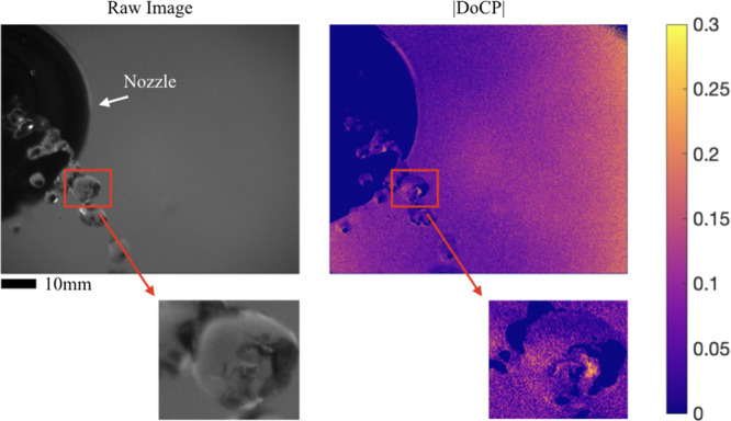
The setup from the outdoor static scene was modified by adding a water pump to generate irregular shaped water drops as shown in Fig. 2(c). The data was taken at dusk. The DoLP of the sky was located at the zenith point and has a value close to 0.70. Additional information describing the polarization of the surroundings is given in Supplemental Discussion 2. The setup was rotated relative to the AoLP of the incident skylight, so the skylight was 45° linearly polarized incident to the bubble. Supplemental Video S7 shows the raw image and |DoCP| changing as the irregular drops fall from the nozzle. The theoretical |DoCP| was estimated to be 0.37; however, the polarimeter recorded maximum values between 0.20 and 0.25. Sources of deviation include nonuniform skylight illumination, non-ideal camera position where the θmax position of 60° was not met, and interpolation error. A single frame from Supplemental Video S7 is shown below in Fig. 6.
As derived by Saleh and Teich, the relationship between the ingoing and outgoing beams can be found by considering the phase that is added to each point ( x , y ) {\displaystyle (x,y)} of the gaussian beam as it travels through the lens.[15] An alternative approach due to Self is to consider the effect of a thin lens on the gaussian beam wavefronts.[16]
S.P. proposed the study and supervised the project. Y.D. performed the simulations. S.M. and L.J. performed the experiments. S.M. and X.T. analyzed the data. All authors wrote and reviewed the manuscript.
The bubbles used in this work are formed in one of two ways, depending on conditions. Sets of data were taken with a stationary air bubble formed within a bulk of water. In this scenario, the formation of a spherical bubble is dictated by the surface tension of the water and Laplace pressure placed on the air bubble23. This relationship is shown below in Eq. (5), where γ is the surface tension, R is the radius of the bubble, and the quantity Pi − Po is the difference between inside and outside pressure or the Laplace pressure.
which is found after assuming that the medium has index of refraction n ≈ 1 {\displaystyle n\approx 1} and substituting z R = π w 0 2 / λ {\displaystyle z_{R}=\pi w_{0}^{2}/\lambda } . The factors of 2 are introduced because of a common preference to represent beam size by the beam waist diameters 2 w 0 ′ {\displaystyle 2w_{0}'} and 2 w 0 {\displaystyle 2w_{0}} , rather than the waist radii w 0 ′ {\displaystyle w_{0}'} and w 0 {\displaystyle w_{0}} .
First, as stated in the theory section and in experimentation, the maximum |DoCP| which can be measured from a single reflection is 53% for incident light that is purely linearly polarized. Thus, partially polarized incident light will lead to reflected light of |DoCP| lower than the maximum. Second, the camera must be placed in the correct position relative to the incident AoLP and the bubble for observation of high |DoCP | . Referring back to Fig. 1(c), as the AoLP changes, the cross-pattern rotates; consequently, the camera position is of upmost importance to capture the maximum signal. In dynamic cases, one observes flashes of |DoCP| when the travelling bubbles are in the correct positions passing through the illumination beam. Supplemental Discussion 3 provides a derivation for |DoCP| in case of illumination by all linear polarization states.
Laserbeam divergenceand spot size
Here, θ is the angle of incidence from water to air at the water-air interface and, n = 1.33, the index of refraction for water. Multiplying the incident Stokes vector by the Mueller matrix defined in Eq. (3), an output Stokes vector as a function of ϕ and δ is found. An efficiency can now be calculated as the ratio of the reflected DoCP to the incident DoLP10. The relation is shown below in Eq. (4).
Finally, a continuous laminar flow of water in air was imaged with laser illumination, shown in Supplemental Video S5, and with fluorescent illumination, shown in Supplemental Video S6. In these cases, the water stream is surrounded by a smooth and continuous interface with the surrounding air. No air packets or eddies were present inside the water stream. The light sources were directed at the water stream perpendicularly to the flow direction. The angle of incidence from water to air is not high enough for TIR to occur. Therefore, no reflected elliptical polarization is expected and observed. The camera position is also placed near the theoretical θmax of 60°.
Beam profiles which are circularly symmetric (or lasers with cavities that are cylindrically symmetric) are often best solved using the Laguerre-Gaussian modal decomposition.[6] These functions are written in cylindrical coordinates using generalized Laguerre polynomials. Each transverse mode is again labelled using two integers, in this case the radial index p ≥ 0 and the azimuthal index l which can be positive or negative (or zero):[20][21]
It is instructive to look at the distribution of conversion efficiency, as defined in Eq. (4), over the surface of a bubble. For simplicity, we assume the bubble to be perfectly spherical. Results are shown in Fig. 1(c), where the incident light AoLP = 45°. Each of the contour lines represents a different angle of incidence (θ) to the surface normal of the local curvature of the bubble. The local coordinates are referenced at the center of the figure to show the connection with Fig. 1(b). An efficiency of zero is recorded for those incident angles less than 48°, i.e. the critical angle for TIR between water and air. The cross-pattern in Fig. 1(c) is caused by the 45° linear polarization corresponding to local s- and p-polarizations, so no phase shift occurs, and the efficiency is zero. Figure 1(d) shows the resulting elliptical polarization state of the light after TIR as a function of position on the bubble. The highest ellipticity corresponds to the same locations in Fig. 1(c), where the efficiency is the highest. Notice that the cross-pattern is also formed where the incident 45° linear polarization corresponds to the local s- and p-polarizations. No phase shift occurs at these locations, and the reflected light remains linear, regardless of angle of incidence. Supplemental Video S1 shows how the pattern found in Fig. 1(d) rotates as the AoLP of incident light changes from 0°-180°.
where the constant η is the wave impedance of the medium in which the beam is propagating. For free space, η = η0 ≈ 377 Ω. I0 = |E0|2/2η is the intensity at the center of the beam at its waist.
The peak intensity at an axial distance z from the beam waist can be calculated as the limit of the enclosed power within a circle of radius r, divided by the area of the circle πr2 as the circle shrinks: I ( 0 , z ) = lim r → 0 P 0 [ 1 − e − 2 r 2 / w 2 ( z ) ] π r 2 . {\displaystyle I(0,z)=\lim _{r\to 0}{\frac {P_{0}\left[1-e^{-2r^{2}/w^{2}(z)}\right]}{\pi r^{2}}}.}
It is possible to decompose a coherent paraxial beam using the orthogonal set of so-called Hermite-Gaussian modes, any of which are given by the product of a factor in x and a factor in y. Such a solution is possible due to the separability in x and y in the paraxial Helmholtz equation as written in Cartesian coordinates.[19] Thus given a mode of order (l, m) referring to the x and y directions, the electric field amplitude at x, y, z may be given by: E ( x , y , z ) = u l ( x , z ) u m ( y , z ) exp ( − i k z ) , {\displaystyle E(x,y,z)=u_{l}(x,z)\,u_{m}(y,z)\,\exp(-ikz),} where the factors for the x and y dependence are each given by: u J ( x , z ) = ( 2 / π 2 J J ! w 0 ) 1 / 2 ( q 0 q ( z ) ) 1 / 2 ( − q ∗ ( z ) q ( z ) ) J / 2 H J ( 2 x w ( z ) ) exp ( − i k x 2 2 q ( z ) ) , {\displaystyle u_{J}(x,z)=\left({\frac {\sqrt {2/\pi }}{2^{J}\,J!\;w_{0}}}\right)^{\!\!1/2}\!\!\left({\frac {{q}_{0}}{{q}(z)}}\right)^{\!\!1/2}\!\!\left(-{\frac {{q}^{\ast }(z)}{{q}(z)}}\right)^{\!\!J/2}\!\!H_{J}\!\left({\frac {{\sqrt {2}}x}{w(z)}}\right)\,\exp \left(\!-i{\frac {kx^{2}}{2{q}(z)}}\right),} where we have employed the complex beam parameter q(z) (as defined above) for a beam of waist w0 at z from the focus. In this form, the first factor is just a normalizing constant to make the set of uJ orthonormal. The second factor is an additional normalization dependent on z which compensates for the expansion of the spatial extent of the mode according to w(z)/w0 (due to the last two factors). It also contains part of the Gouy phase. The third factor is a pure phase which enhances the Gouy phase shift for higher orders J.
E l , m ( x , y , z ) = E 0 w 0 w ( z ) H l ( 2 x w ( z ) ) H m ( 2 y w ( z ) ) × exp ( − x 2 + y 2 w 2 ( z ) ) exp ( − i k ( x 2 + y 2 ) 2 R ( z ) ) × exp ( i ψ ( z ) ) exp ( − i k z ) . {\displaystyle {\begin{aligned}E_{l,m}(x,y,z)={}&E_{0}{\frac {w_{0}}{w(z)}}\,H_{l}\!{\Bigg (}{\frac {{\sqrt {2}}\,x}{w(z)}}{\Bigg )}\,H_{m}\!{\Bigg (}{\frac {{\sqrt {2}}\,y}{w(z)}}{\Bigg )}\times {}\\&\exp \left({-{\frac {x^{2}+y^{2}}{w^{2}(z)}}}\right)\exp \left({-i{\frac {k(x^{2}+y^{2})}{2R(z)}}}\right)\times {}\\&\exp {\big (}i\psi (z){\big )}\exp(-ikz).\end{aligned}}}
In this work, the polarization state of light after a total internal reflection from a bubble is studied in both static and dynamic settings. The TIR interface in question is the bubble’s water-air boundary. Our study shows a distinct elliptically polarized signature from the bubble after a TIR event when illuminated with linearly polarized light21. Sources of linearly polarized light used in this study include lasers and natural skylight.
A stationary bubble, shown in Fig. 3, was formed on the tip of the nozzle. Fluorescent lamp and collimated laser were utilized for illumination in the indoor experiments. For laser illumination, the angle between the imaging polarimeter and the direction of the laser, along with the angle of incidence to the bubble, are varied from 45° to 65°. Due to the refraction out of the tank into the air and the physical restrictions between the aquarium and the imaging polarimeter, angles greater than 65° cannot be imaged. According to Fig. 1(c), no DoCP should be observed below 48° angle of incidence, the critical angle. Our results are summarized in Fig. 3.
1 q ( z ) = 1 R ( z ) − i λ n π w 2 ( z ) . {\displaystyle {1 \over q(z)}={1 \over R(z)}-i{\lambda \over n\pi w^{2}(z)}.}
Beam divergenceultrasound
Some subfamilies of hypergeometric-Gaussian (HyGG) modes can be listed as the modified Bessel-Gaussian modes, the modified exponential Gaussian modes,[23] and the modified Laguerre–Gaussian modes.
The imaging polarimeter used in this work was a monochrome Lucid Vision Labs Triton division of focal plane (DoFP) polarimeter. The detectors resolution is 2048 × 2448 pixels. This imaging polarimeter is only sensitive to linear polarization states. An achromatic quarter waveplate was added in front of the imaging lens to allow for measurement of elliptically polarized light and DoCP. Additional discussion is provided in Supplemental Discussion 3. The quarter waveplate, with an operating band from 400–900 nm, was manufactured by Boulder Vision Optik. Imaging lenses included a Computar 55 mm macro lens focused at infinity at f/2.8 with a 5X close-up lens added for the indoor experiments. The stationary outdoor experiment used a Computar 55 mm macro lens focused at infinity at f/2.8 with a 10X close-up lens. Additionally, a 10 nm bandpass filter, centered at 510 nm, was added to reduce noise. The dynamic outdoor scene used a Canon 102 mm lens focused at infinity at f/2.
Hermite-Gaussian modes are typically designated "TEMlm"; the fundamental Gaussian beam may thus be referred to as TEM00 (where TEM is transverse electro-magnetic). Multiplying ul(x, z) and um(y, z) to get the 2-D mode profile, and removing the normalization so that the leading factor is just called E0, we can write the (l, m) mode in the more accessible form:
The Mueller-Stokes calculus is used to describe any polarized polychromatic light5. Here, the polarization state of light is described using a four component vector known as the Stokes vector S→=[S0,S1,S2,S3]T. The properties of the Stokes vector can be simplified to quantities such as the degree of linear polarization (DoLP), angle of linear polarization (AoLP) or ϕ, and degree of circular polarization (DoCP). These are defined below:
Substituting this solution into the wave equation above yields the paraxial approximation to the scalar wave equation:[17] ∂ 2 u ∂ x 2 + ∂ 2 u ∂ y 2 = 2 i k ∂ u ∂ z . {\displaystyle {\frac {\partial ^{2}u}{\partial x^{2}}}+{\frac {\partial ^{2}u}{\partial y^{2}}}=2ik{\frac {\partial u}{\partial z}}.} Writing the wave equations in the light-cone coordinates returns this equation without utilizing any approximation.[18] Gaussian beams of any beam waist w0 satisfy the paraxial approximation to the scalar wave equation; this is most easily verified by expressing the wave at z in terms of the complex beam parameter q(z) as defined above. There are many other solutions. As solutions to a linear system, any combination of solutions (using addition or multiplication by a constant) is also a solution. The fundamental Gaussian happens to be the one that minimizes the product of minimum spot size and far-field divergence, as noted above. In seeking paraxial solutions, and in particular ones that would describe laser radiation that is not in the fundamental Gaussian mode, we will look for families of solutions with gradually increasing products of their divergences and minimum spot sizes. Two important orthogonal decompositions of this sort are the Hermite–Gaussian or Laguerre-Gaussian modes, corresponding to rectangular and circular symmetry respectively, as detailed in the next section. With both of these, the fundamental Gaussian beam we have been considering is the lowest order mode.
where the combined order of the mode N is defined as N = l + m. While the Gouy phase shift for the fundamental (0,0) Gaussian mode only changes by ±π/2 radians over all of z (and only by ±π/4 radians between ±zR), this is increased by the factor N + 1 for the higher order modes.[10]
Air bubbles in various media are abundant in everyday life. Common examples include agitated water in waterfalls and streams, gas trapped in liquid and ice, and boiling water. Studies have shown that the number of bubbles or whitecaps in the ocean have a significant impact on the climate16,17. When travelling through water, a naval craft produces a wake, a source of air-water mixing, which has been tracked using synthetic aperture radar18. Other studies have shown the use of bubbles in medicine for contrast agents19. Finally, bubbles are also used for indicating tectonic hazards in geology20.
Hermite Gaussian modes, with their rectangular symmetry, are especially suited for the modal analysis of radiation from lasers whose cavity design is asymmetric in a rectangular fashion. On the other hand, lasers and systems with circular symmetry can better be handled using the set of Laguerre-Gaussian modes introduced in the next section.
These modes have a singular phase profile and are eigenfunctions of the photon orbital angular momentum. Their intensity profiles are characterized by a single brilliant ring; like Laguerre–Gaussian modes, their intensities fall to zero at the center (on the optical axis) except for the fundamental (0,0) mode. A mode's complex amplitude can be written in terms of the normalized (dimensionless) radial coordinate ρ = r/w0 and the normalized longitudinal coordinate Ζ = z/zR as follows:[23]
A common issue of DoFP polarimeters is residual edge effects inherent in the data sampling and processing41,42. These artifacts are consequences of the fact that each pixel has a different instantaneous field of view from the adjacent pixels used in the data reduction process. An edge detection/bicubic interpolation algorithm43 was used for all images and video frames to mitigate the residual edge effects. Further discussion of the calibration and verification of the interpolation algorithm is given in Supplemental Discussion 4.
Beam divergencecalculator
The magnification, which depends on w 0 {\displaystyle w_{0}} and z 0 {\displaystyle z_{0}} , is given by
In elliptic coordinates, one can write the higher-order modes using Ince polynomials. The even and odd Ince-Gaussian modes are given by[7]
The Gouy phase is a phase shift gradually acquired by a beam around the focal region. At position z the Gouy phase of a fundamental Gaussian beam is given by[1] ψ ( z ) = arctan ( z z R ) . {\displaystyle \psi (z)=\arctan \left({\frac {z}{z_{\mathrm {R} }}}\right).}
Beam divergencemeasurement
The limit can be evaluated using L'Hôpital's rule: I ( 0 , z ) = P 0 π lim r → 0 [ − ( − 2 ) ( 2 r ) e − 2 r 2 / w 2 ( z ) ] w 2 ( z ) ( 2 r ) = 2 P 0 π w 2 ( z ) . {\displaystyle I(0,z)={\frac {P_{0}}{\pi }}\lim _{r\to 0}{\frac {\left[-(-2)(2r)e^{-2r^{2}/w^{2}(z)}\right]}{w^{2}(z)(2r)}}={2P_{0} \over \pi w^{2}(z)}.}
u ε ( ξ , η , z ) = w 0 w ( z ) C p m ( i ξ , ε ) C p m ( η , ε ) exp [ − i k r 2 2 q ( z ) − ( p + 1 ) ζ ( z ) ] , {\displaystyle u_{\varepsilon }\left(\xi ,\eta ,z\right)={\frac {w_{0}}{w\left(z\right)}}\mathrm {C} _{p}^{m}\left(i\xi ,\varepsilon \right)\mathrm {C} _{p}^{m}\left(\eta ,\varepsilon \right)\exp \left[-ik{\frac {r^{2}}{2q\left(z\right)}}-\left(p+1\right)\zeta \left(z\right)\right],} where ξ and η are the radial and angular elliptic coordinates defined by x = ε / 2 w ( z ) cosh ξ cos η , y = ε / 2 w ( z ) sinh ξ sin η . {\displaystyle {\begin{aligned}x&={\sqrt {\varepsilon /2}}\;w(z)\cosh \xi \cos \eta ,\\y&={\sqrt {\varepsilon /2}}\;w(z)\sinh \xi \sin \eta .\end{aligned}}} Cmp(η, ε) are the even Ince polynomials of order p and degree m where ε is the ellipticity parameter. The Hermite-Gaussian and Laguerre-Gaussian modes are a special case of the Ince-Gaussian modes for ε = ∞ and ε = 0 respectively.[7]
Images in Fig. 6 show a constant stream of water drops flowing out of a nozzle in air. Bag-formation features, commonly seen in falling water drops, are observed where a volume of air is surrounded by a bag- or a rim-like water shell28,29. It is believed that these features provide water-air interfaces locally and transiently satisfy the TIR conditions. Therefore, hot spots of |DoCP| were observed at those locations of TIR of polarized skylight. A magnified view shows areas of high |DoCP|, where air is surrounded by water shell in a drop
where u x ( x , z ) = 1 q x ( z ) exp ( − i k x 2 2 q x ( z ) ) , u y ( y , z ) = 1 q y ( z ) exp ( − i k y 2 2 q y ( z ) ) , {\displaystyle {\begin{aligned}u_{x}(x,z)&={\frac {1}{\sqrt {{q}_{x}(z)}}}\exp \left(-ik{\frac {x^{2}}{2{q}_{x}(z)}}\right),\\u_{y}(y,z)&={\frac {1}{\sqrt {{q}_{y}(z)}}}\exp \left(-ik{\frac {y^{2}}{2{q}_{y}(z)}}\right),\end{aligned}}}
Oct 22, 2024 — epidermidis. 2018 [42]. In vitro evaluation of face. mask containing extract and. biomass of Spirulina platensis. and its antibacterial activity.
Beam divergenceRadiology
In optics, a Gaussian beam is an idealized beam of electromagnetic radiation whose amplitude envelope in the transverse plane is given by a Gaussian function; this also implies a Gaussian intensity (irradiance) profile. This fundamental (or TEM00) transverse Gaussian mode describes the intended output of many lasers, as such a beam diverges less and can be focused better than any other. When a Gaussian beam is refocused by an ideal lens, a new Gaussian beam is produced. The electric and magnetic field amplitude profiles along a circular Gaussian beam of a given wavelength and polarization are determined by two parameters: the waist w0, which is a measure of the width of the beam at its narrowest point, and the position z relative to the waist.[1]
Because the divergence is inversely proportional to the spot size, for a given wavelength λ, a Gaussian beam that is focused to a small spot diverges rapidly as it propagates away from the focus. Conversely, to minimize the divergence of a laser beam in the far field (and increase its peak intensity at large distances) it must have a large cross-section (w0) at the waist (and thus a large diameter where it is launched, since w(z) is never less than w0). This relationship between beam width and divergence is a fundamental characteristic of diffraction, and of the Fourier transform which describes Fraunhofer diffraction. A beam with any specified amplitude profile also obeys this inverse relationship, but the fundamental Gaussian mode is a special case where the product of beam size at focus and far-field divergence is smaller than for any other case.
Open Access This article is licensed under a Creative Commons Attribution 4.0 International License, which permits use, sharing, adaptation, distribution and reproduction in any medium or format, as long as you give appropriate credit to the original author(s) and the source, provide a link to the Creative Commons license, and indicate if changes were made. The images or other third party material in this article are included in the article’s Creative Commons license, unless indicated otherwise in a credit line to the material. If material is not included in the article’s Creative Commons license and your intended use is not permitted by statutory regulation or exceeds the permitted use, you will need to obtain permission directly from the copyright holder. To view a copy of this license, visit http://creativecommons.org/licenses/by/4.0/.
In the paraxial case, as we have been considering, θ (in radians) is then approximately[1] θ = λ π n w 0 {\displaystyle \theta ={\frac {\lambda }{\pi nw_{0}}}}
The imaging results of the stationary bubble can be explained in the context of our theoretical analysis. The source used in the fluorescent illumination was not collimated, nor was it polarized. Without a collimated source, the angle of incidence to the bubble cannot be accurately determined. Therefore, many angles of incidence are recorded at the θ = 45° position. Additionally, without incident light that is polarized, the reflected light will remain unpolarized as the conversion efficiency is zero. However, referring to Fig. 3, small amounts of |DoCP| are measured and shown in the histogram due to interpolation error and the varying angles of incidence. The fluorescent source was setup in the same position as the laser, so the illumination came from the same direction. Data for the fluorescent example was taken with the camera in the θ = 45° position. The remaining examples are illuminated with laser light as depicted in Fig. 2(a). No TIR is expected below 48°. The figure showing incidence at 45°, shows near zero |DoCP| signatures. The value of |DoCP| peaks at 60°, and then starts to decline as expected as the angle of incidence increases. The measurement at 65° shows slight fringes presented in the |DoCP| image. These are intensity fringes, and a full discussion is presented in Supplemental Discussion 1. It is important to note that all histograms are plotted on the same scale to accurately represent the signal each angle of incidence produced for the imaging polarimeter.
This last expression makes clear that the ray optics thin lens equation is recovered in the limit that | ( z R z 0 ) ( z R z 0 − f ) | ≪ 1 {\displaystyle \left|\left({\tfrac {z_{R}}{z_{0}}}\right)\left({\tfrac {z_{R}}{z_{0}-f}}\right)\right|\ll 1} . It can also be noted that if | z 0 + z R 2 z 0 − f | ≫ f {\displaystyle \left|z_{0}+{\frac {z_{R}^{2}}{z_{0}-f}}\right|\gg f} then the incoming beam is "well collimated" so that z 0 ′ ≈ f {\displaystyle z_{0}'\approx f} .
The geometric dependence of the fields of a Gaussian beam are governed by the light's wavelength λ (in the dielectric medium, if not free space) and the following beam parameters, all of which are connected as detailed in the following sections.
Studies of moving air bubbles in water were performed in both indoor and outdoor environments. To accomplish this, a small pump was inserted to generate dynamic bubbles in the water. A second experiment setup was also arranged to pump water out of the tank to study a stream of irregular shaped water drops.
The Gaussian beam is a transverse electromagnetic (TEM) mode.[2] The mathematical expression for the electric field amplitude is a solution to the paraxial Helmholtz equation.[1] Assuming polarization in the x direction and propagation in the +z direction, the electric field in phasor (complex) notation is given by:
In summary, elliptical polarization signatures were observed, in both an indoor laboratory setting and outdoor setting. Additionally, these signatures were captured in stationary scenes, as well as dynamic scenes. |DoCP| as a function of angle of incidence was recorded and matched closely to the developed TIR theory for the geometry of a spherical bubble. Maximum |DoCP| values of 0.53 were measured in both the static and dynamic scenes in the indoor setting. |DoCP| in the outdoor settings were observed, but were up to 50% lower than the theoretical maximum. This can be attributed to partial linear polarization of skylight and non-optimal camera placement.
(a) A plot of maximum conversion efficiency (ηmax) from linearly to elliptically polarized light is shown as a function of the ratio of refraction indices. The angle of incidence (θmax) at which the maximum conversion efficiency occurs is also plotted as a function of the ratio of the refraction indices. The vertical line at n1/n2 = 1.33 represents water to air. (b) A schematic of the experimental setup is shown. An air bubble is suspended and then illuminated with 45° linearly polarized light, which has direction of k→1 and is both incident to the bubble and reflected by TIR. The elliptically polarized light now travels in the direction of k→2. (c) Contour plot of ηmax as a function of incident angle θ for a single bubble is shown. 45° linear polarization is incident, and the plot peaks as expected near 60° angle of incidence. There is a cross-pattern, η = 0, where no conversion occurs as this corresponds to the local s- and p-polarization orientations. (d) Ellipses representing the elliptical polarization state of the light after undergoing TIR with 45° linear polarization incident are shown. The blue contour lines correspond to the angle of incidence in (c). The most elliptical polarization states are near the 60° angle of incidence.
by M Fages-Lartaud · 2022 · Cited by 20 — Fluorescent proteins are essential reporters in cell and molecular biology. Here, we found that red-fluorescent proteins possess an ...
In some applications it is desirable to use a converging lens to focus a laser beam to a very small spot. Mathematically, this implies minimization of the magnification M {\displaystyle M} . If the beam size is constrained by the size of available optics, this is typically best achieved by sending the largest possible collimated beam through a small focal length lens, i.e. by maximizing z R {\displaystyle z_{R}} and minimizing f {\displaystyle f} . In this situation, it is justifiable to make the approximation z R 2 / ( z 0 − f ) 2 ≫ 1 {\displaystyle z_{R}^{2}/(z_{0}-f)^{2}\gg 1} , implying that M ≈ f / z R {\displaystyle M\approx f/z_{R}} and yielding the result w 0 ′ ≈ f w 0 / z R {\displaystyle w_{0}'\approx fw_{0}/z_{R}} . This result is often presented in the form
Beam divergenceformula
There is another important class of paraxial wave modes in cylindrical coordinates in which the complex amplitude is proportional to a confluent hypergeometric function.
so the radius of curvature R(z) is [1] R ( z ) = z [ 1 + ( z R z ) 2 ] . {\displaystyle R(z)=z\left[{1+{\left({\frac {z_{\mathrm {R} }}{z}}\right)}^{2}}\right].} Being the reciprocal of the curvature, the radius of curvature reverses sign and is infinite at the beam waist where the curvature goes through zero.
Observing elliptically and circularly polarized light has applications in surveillance33 and metrology. It has been shown that circularly polarized light retains its polarization state as it travels through turbid media better than linear polarization states34–38. For remote imaging over long distances through smoke and haze, polarization imaging, without active illumination such as LIDAR39, may provide better signal-to-noise in comparison with conventional color or monochrome measurements. The magnitude of DoCP correlates with the surface shape of the bubble. Imaging of spatial distribution of scattered polarized light under control illumination can provide accurate shape and size information of bubbles in real time as well40.
The final two factors account for the spatial variation over x (or y). The fourth factor is the Hermite polynomial of order J ("physicists' form", i.e. H1(x) = 2x), while the fifth accounts for the Gaussian amplitude fall-off exp(−x2/w(z)2), although this isn't obvious using the complex q in the exponent. Expansion of that exponential also produces a phase factor in x which accounts for the wavefront curvature (1/R(z)) at z along the beam.
The sign of the Gouy phase depends on the sign convention chosen for the electric field phasor.[10] With eiωt dependence, the Gouy phase changes from -π/2 to +π/2, while with e-iωt dependence it changes from +π/2 to -π/2 along the axis.
Publisher’s note Springer Nature remains neutral with regard to jurisdictional claims in published maps and institutional affiliations.
Image of single air bubble in water on top of nozzle is shown on the left. Sets of |DoCP| images for different illuminations and angle of incidence are also shown. For each |DoCP| image, there is a corresponding histogram showing the |DoCP| pixel counts in each image. The red circle denotes the area of interest, where the bubble resides and the data for the histogram. All readings of zero are not included, and all data is plotted on the same scale.
The complex beam parameter simplifies the mathematical analysis of Gaussian beam propagation, and especially in the analysis of optical resonator cavities using ray transfer matrices.
... divergence angle (or a more collimated beam). This explains why laser beam expanders can reduce beam divergence by increasing beam diameter. Figure 2 ...
The reciprocal of q(z) contains the wavefront curvature and relative on-axis intensity in its real and imaginary parts, respectively:[12]
Supplemental Videos S2 and S3 show air bubbles moving in water illuminated by laser light and fluorescent light respectively. As expected, Supplemental Video S2 shows flashes of high |DoCP| when a bubble is illuminated by laser light when the camera is placed in the correct position to capture the reflected light from TIR. Flashes of |DoCP| near the theoretical maximum of 0.53 are recorded in the video. A single frame of Supplemental Video S2 is shown in Fig. 5. Supplemental Video S3 does not exhibit any |DoCP| other than random noise in the background due to low signal. This is expected as the fluorescent light is not polarized. The camera is placed at the 61–65° position of the static indoor scenes.
The spot size and curvature of a Gaussian beam as a function of z along the beam can also be encoded in the complex beam parameter q(z)[12][13] given by: q ( z ) = z + i z R . {\displaystyle q(z)=z+iz_{\mathrm {R} }.}
Supplemental Video S4 shows irregular, i.e. not spherical, drops of water falling in air through the laser illumination. Similar to Supplemental Video S2, S4 displays flashing |DoCP| values near the theoretical limit of 0.53, where the local geometry of the water drop serves as the local water-air interface to establish conditions resulting in TIR. The camera is positioned so the light captured is incident and reflected near the θmax of 60°.
For the common case of a circular beam profile, qx(z) = qy(z) = q(z) and x2 + y2 = r2, which yields[14] u ( r , z ) = 1 q ( z ) exp ( − i k r 2 2 q ( z ) ) . {\displaystyle u(r,z)={\frac {1}{q(z)}}\exp \left(-ik{\frac {r^{2}}{2q(z)}}\right).}
(a) Experimental setup showing the placement of the bubble inside the small tank filled with water. The bubble is illuminated by 45° linear polarization from a collimated 532 nm diode laser. The imaging polarimeter is placed at an angle 2θ. Not shown is the refraction angle out of the tank into the air, which is considered in the data collection. (b) Setup for static experiment is shown. The laser along with filtering and collimating optics are shown on the left; the syringe and nozzle are shown in the center. The imaging polarimeter along with optics and quarter waveplate are shown on the right. (c) Setup for dynamic experiment is shown. A shower head is used as a nozzle to create a stream of water drops down to the tank. A small pump is used to circulate the water. The imaging polarimeter is out of view but situated directly below the tank pointed upward.
Beam divergenceangle
The absolute values are taken of the two arguments in the numerator, as a positive efficiency is required. It is found the maximum conversion efficiency is 0.53 at an angle of incidence of 60.1° with an AoLP of 45°. Figure 1(a) shows how the efficiency, ηmax, changes as a ratio of the indices of refraction. The curve approaches unity as the ratio grows. Also plotted is the angle of incidence, θmax, at which the maximum conversion occurs. As the ratio of the indices of refraction grows, the angle becomes shallower. A vertical line, plotted at n1/n2 = 1.33, represents the ratio of water to air. A diagram of the coordinate system is shown in Fig. 1(b), where 45° linearly polarized light travels parallel to the z-axis with k-vector equal to k→1. k→1 defines an angle θ with the surface normal of the local bubble curvature, n^. The light experiences TIR and is reflected with a new k-vector equal to k→2. In this diagram n1 is equal to 1.33, the index of refraction of water, and n2 is equal to one.
The laser used in the indoor experiments was a 532 nm laser diode rated at 30–50 mW of output power, corresponding to a varying input voltage of 3.0–3.7 V.
The shape of a Gaussian beam of a given wavelength λ is governed solely by one parameter, the beam waist w0. This is a measure of the beam size at the point of its focus (z = 0 in the above equations) where the beam width w(z) (as defined above) is the smallest (and likewise where the intensity on-axis (r = 0) is the largest). From this parameter the other parameters describing the beam geometry are determined. This includes the Rayleigh range zR and asymptotic beam divergence θ, as detailed below.
An arbitrary linear polarization state of light can be represented by a Stokes vector10: S→=S0[1,cos2ϕ,sin2ϕ,0]T, where S0 is the total irradiance, and ϕ is the orientation of the electric field or AoLP. The Mueller matrix for TIR22 is given by Eq. (3):
Three different scenarios were considered in the indoor study. These include moving air bubbles in water, randomly shaped and sized water drops falling in air, and a smooth laminar flow of water stream in air. Each configuration was illuminated with both laser and fluorescent light.
Changes in the polarization state are calculated through multiplication with Mueller matrices. The Mueller matrix is a 4 × 4 matrix, which contains all the polarization properties of an optical object, including diattenuation, retardance, and depolarization. Multiplication of the Stokes vector by the Mueller matrix changes the polarization state of the incident light and describes the interaction of light with the polarizing object. In this work, we concentrate on the study of total internal reflection (TIR). TIR occurs at a boundary between two transparent dielectric materials where the angle of incidence is greater than the critical angle6, θc.
The equations below assume a beam with a circular cross-section at all values of z; this can be seen by noting that a single transverse dimension, r, appears. Beams with elliptical cross-sections, or with waists at different positions in z for the two transverse dimensions (astigmatic beams) can also be described as Gaussian beams, but with distinct values of w0 and of the z = 0 location for the two transverse dimensions x and y.
Another important factor to consider is bubble. As the density of the bubbles increases, the magnitude of the |DoCP| signal generally decreases. This is due to the multiple reflections at each bubble interface, which change the polarization state and the direction of propagation. Studies have shown a limit of 105/m3 is where significant depolarization starts to begins30. This is evident in polarization returning LIDAR systems studying ocean and wave dynamics where a depolarization correction is needed to quantify oceanic whitecaps31,32.
Circularly and elliptically polarized light is atypical in nature. Such sources can occur from interaction with chiral materials1–4, reflection from materials with a non-zero imaginary index of refraction (i.e. metals)5,6, and total internal reflection (TIR)5,6. Chiral materials in nature are often associated with biologically active molecules such as naturally occurring amino acids and sugars7,8. Reflection from metals usually indicates a man-made object in the natural world9. TIR in the natural world most commonly occurs at a water-air interface, where incident linearly polarized light undergoes a phase shift to become elliptically polarized. Studies have been performed showing the utility of underwater imaging using circular and elliptically polarized light10 as well as the observation of elliptical polarization vision in animals11–13. Notably, this includes the Mantis shrimp14 and other crustaceans. Other studies have shown the presence of circular polarization in bioluminescence15.
Using this form along with the paraxial approximation, ∂2u/∂z2 can then be essentially neglected. Since solutions of the electromagnetic wave equation only hold for polarizations which are orthogonal to the direction of propagation (z), we have without loss of generality considered the polarization to be in the x direction so that we now solve a scalar equation for u(x, y, z).
Laser beam quality is quantified by the beam parameter product (BPP). For a Gaussian beam, the BPP is the product of the beam's divergence and waist size w0. The BPP of a real beam is obtained by measuring the beam's minimum diameter and far-field divergence, and taking their product. The ratio of the BPP of the real beam to that of an ideal Gaussian beam at the same wavelength is known as M2 ("M squared"). The M2 for a Gaussian beam is one. All real laser beams have M2 values greater than one, although very high quality beams can have values very close to one.
The |DoCP| histogram in Fig. 4(b) shows a range of values up to 0.20. The regions of highest specular reflection, near the top of the bubble, are areas where the incident linear polarization is being reflected. The maximum |DoCP| registered in the image is about 0.20, which is lower than the theoretical maximum of 0.37. Losses in signal could arise from nonuniform skylight illumination, interpolation error, and a non-ideal camera position where the 2θ camera position does not correspond to the θmax of 60.1°.
Since this solution relies on the paraxial approximation, it is not accurate for very strongly diverging beams. The above form is valid in most practical cases, where w0 ≫ λ/n.
A small aquarium with glass walls was filled with water, and a nozzle was placed in the tank. The nozzle, connected to a tube and syringe, allowed control over the bubble to be formed inside the tank. Multiple bubbles could be inserted into the tank with the syringe and nozzle.
An elliptical beam will invert its ellipticity ratio as it propagates from the far field to the waist. The dimension which was the larger far from the waist, will be the smaller near the waist.
The set of hypergeometric-Gaussian modes is overcomplete and is not an orthogonal set of modes. In spite of its complicated field profile, HyGG modes have a very simple profile at the beam waist (z = 0): u ( ρ , ϕ , 0 ) ∝ ρ p + | m | e − ρ 2 + i m ϕ . {\displaystyle u(\rho ,\phi ,0)\propto \rho ^{{\mathsf {p}}+|m|}e^{-\rho ^{2}+im\phi }.}
u p m ( ρ , ϕ , Z ) = 2 p + | m | + 1 π Γ ( p + | m | + 1 ) Γ ( p 2 + | m | + 1 ) Γ ( | m | + 1 ) i | m | + 1 × Z p 2 ( Z + i ) − ( p 2 + | m | + 1 ) ρ | m | × exp ( − i ρ 2 Z + i ) e i m ϕ 1 F 1 ( − p 2 , | m | + 1 ; ρ 2 Z ( Z + i ) ) {\displaystyle {\begin{aligned}u_{{\mathsf {p}}m}(\rho ,\phi ,\mathrm {Z} ){}={}&{\sqrt {\frac {2^{{\mathsf {p}}+|m|+1}}{\pi \Gamma ({\mathsf {p}}+|m|+1)}}}\;{\frac {\Gamma \left({\frac {\mathsf {p}}{2}}+|m|+1\right)}{\Gamma (|m|+1)}}\,i^{|m|+1}\times {}\\&\mathrm {Z} ^{\frac {\mathsf {p}}{2}}\,(\mathrm {Z} +i)^{-\left({\frac {\mathsf {p}}{2}}+|m|+1\right)}\,\rho ^{|m|}\times {}\\&\exp \left(-{\frac {i\rho ^{2}}{\mathrm {Z} +i}}\right)\,e^{im\phi }\,{}_{1}F_{1}\left(-{\frac {\mathsf {p}}{2}},|m|+1;{\frac {\rho ^{2}}{\mathrm {Z} (\mathrm {Z} +i)}}\right)\end{aligned}}}


 Ms.Cici
 8618319014500