
USAF 1951 - determination resolulution - air force target
In Section 2.3, we propose a symmetric measurement scheme to improve the system’s accuracy. The results show the effectiveness of the method. Here, the error analyses of the symmetric measurement are given to verify the method theoretically.
This section collects any data citations, data availability statements, or supplementary materials included in this article.
Then, the error estimation with the symmetric measurement scheme as proposed in Section 4.2 is given. σnair and σnE are the same as in Equations (22) and (24). However, for σnS, the influence of σβ, σy1, and σy2 can be reduced. σnS can be obtained by
Figure 2A shows the layout of the optical measurement configuration of the system. The thin laser beam passes through the microscopic objective and collimating lens to generate a broad collimated laser beam, which is used as a light source. The broad beam is focused by a convergence lens to the focal point as a focusing probe, which is coincident to the surface vertex of the sample. The incident angle of the chief ray of the probe is close to the Brewster angle. Polarizers 1 and 2, through which the light passes, are both in P polarization state, guaranteeing that the probe is a P-polarized beam. After the probe is reflected by the sample, the reflected light propagates to the CMOS detector placed at a distance d away from the sample. The resolution and the pixel size of the image plane are denoted as M × N and p, respectively.
Glass refractiveindex
The measurement error σnE of the refractive index caused by the angular measurement error σθE of incident angle θE can be obtained by differentiating Equation (5) with respect to σθE as
Glass refractiveformula
In this study, we propose a Brewster-Law-based direct and simple measurement method with a focusing probe beam for the refractive index of glasses with arbitrary shapes. A P-polarized laser beam is focused by a convergence lens on the surface of the sample as a focusing probe beam with a size of approximately 10 microns and then reflects to an array detector. The focusing probe beam is the incident light of the system, and the ray parallel to the optical axis of the convergence lens is defined as the chief ray. The incident angle of the chief ray is close to the Brewster angle. According to Brewster’s Law, a dark slit corresponding to the Brewster angle exists in the intensity distribution of the reflected light. Finally, image processing is used to calculate the Brewster angle and the refractive index by finding the minimum intensity position. The refractive index is measured by the reflection from an arbitrary surface of the sample; therefore, the structural parameters are not needed. Given that the probe requires only a tiny area for reflection, the method is available for samples with arbitrary shapes. Additionally, a symmetric measurement scheme is proposed to improve the accuracy. By using these methods, a prism and four spherical lens samples with different refractive indices or radii of curvature are tested and error analyses are carried out. Results indicate that the accuracy can reach 10−4.
Official websites use .gov A .gov website belongs to an official government organization in the United States.
The 3-foot USB 3.0 A to Micro B cable is backed by our Lifetime Warranty, providing guaranteed quality and reliability. Applications. Connecting Micro USB 3.0 ...
The reason for the dark silt formation is presented below. The intensity distribution of the reflected light is determined by the distribution of the incident light and the reflectivity, while that of the collimated laser beam is generally Gaussian and the reflectivity can be calculated by the incident angle. For the focusing probe beam, the incident angles vary at different positions, which follows the model in Figure 3.
Ten measurements were taken for each of the samples listed in Table 1, and each measurement took around five minutes because the mechanical rotation was not fully automatic. Figure 9 shows the data processing results of sample 1 as an example. Figure 9A is the intensity curve in three typical rows from the intensity distribution collected by the CMOS. The vertical axis is the grayscale value, and the horizontal axis is the column coordinate. The red, green, and blue curves correspond to the intensity curves in rows 600, 800, and 1000, respectively. In each curve, a minimum intensity position corresponding to θEi can be found. The column coordinates of the curves are different, which accords with the principle in Section 2.1. Figure 9B shows the row and column coordinates of the minimum intensity position. The vertical axis is the column coordinate, and the horizontal axis is the row coordinate. Different values of θEi make up the curve, and the maximum of the curve corresponds to θE. The results for the other samples are similar. The detailed results and analyses are demonstrated in Section 3.2.1 and Section 3.2.2, respectively.
According to the experimental system, Table 5 shows the estimated error limits of σβ, σx1, σx2, σy1, and σy2. For the measurement of sample 5, θS is set at 1.0647 rad, and the turning radius R = 150 mm, equal to the distance between the CMOS and the rotating center. By the estimated error in Table 5 and Equations (10)–(16), the measurement error σnS can be calculated as
Refractiveindex of diamond
The refractive index, defined as the ratio of the velocity of light in a vacuum and the material, is one of the most important physical parameters of optical glass. With its considerable influence on the working characteristics of optical systems, high-accuracy measurement of this parameter is required. Since the early 1900s, various methods have been proposed [1], including prism coupling [2], critical angle [3], interferometry [4,5], and ellipsometry [6]. Some of them can even determine the refractive index and the structure of the sample simultaneously [7,8,9,10]. These methods are now widely used and can reach high accuracy of up to 10−6, but they are only available for prisms and parallel plates. Samples with only spherical or aspheric surfaces, such as lenses, cannot be tested. However, the measurement of the refractive index of a lens is equally important because of its possible changes during the manufacturing procedure, which may considerably affect the optical properties [11,12].
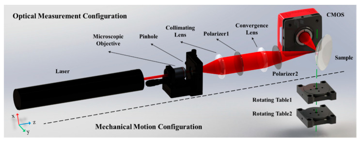
Figure 1 shows the system layout of the proposed refractive index measurement system, which is composed of optical measurement and mechanical motion configurations divided by the black dotted line. The optical measurement configuration is organized for the refractive index measurement, comprising two polarizers and a laser, microscope, collimating lens, convergence lens, sample, and a complementary metal oxide semiconductor (CMOS) array detector. The mechanical motion configuration consists of two coaxial rotating tables, marked as Rotating Table 1 and Rotating Table 2. The green dotted line is the common rotational axis of these tables, which passes through the surface vertex of the sample. Rotating Tables 1 and 2 take control of the sample and the CMOS, respectively.
Reflective objectives utilize a reflective, or mirror-based design. They are often overlooked in comparison to their refractive counterparts, though they can correct for many issues present in the latter. Reflective objectives consist of a primary and secondary mirror system (Figure 6) to magnify and relay the image of the object under inspection. Edmund Optics® utilizes the popular Schwarzschild design, though other designs are available. Since light is reflected by metallic surfaces and not refracted by glass surfaces, reflective objectives do not suffer from the same aberrations as refractive objectives and, thus, do not need the additional designs to compensate for these aberrations. Reflective objectives can produce higher light efficiency as well as better resolving power for fine detail imaging because the system is primarily dependent upon the mirror coating instead of upon the glass substrate being used. Another benefit of reflective objectives is the possibility of working deeper into either the ultra-violet (UV) or infrared (IR) spectral regions due to the use of mirrors compared to conventional refractive optics.
Field of view or FOV is the area of the object that is imaged by a microscope system. The size of the FOV is determined by the objective magnification. When using an eyepiece-objective system, the FOV from the objective is magnified by the eyepiece for viewing. In a camera-objective system, that FOV is relayed onto a camera sensor. The sensor on a camera is rectangular and therefore can only image a portion of the full circular FOV from the objective. In contrast, the retina in your eye can image a circular area and captures the full FOV. This is why the FOV produced by a camera-microscope system is typically slightly smaller than that of an eyepiece-microscope system. Equations 3 and 4 can be used to calculate the FOV in the aforementioned systems. In Equations 3 and 4, $ \small{H_{\small{\text{Camera Sensor}}}} $ is the sensor size of the camera and $ \small{H_{\small{\text{Eyepiece Field Stop}}}} $ is the field stop of the eyepiece.
(A) Layout of the optical measurement configuration; (B) Intensity distribution of the reflected light; (C) Intensity curve of the reflected ray versus the incident angle.
For the focusing probe beam in Figure 1, the focal point of the convergence lens corresponds to the coordinate origin of the model and the optical axis of the incident light corresponds to the Z axis. The chief ray of the incident light lies on the yoz plane, and thus the angle γ is zero and θ is equal to the incident angle α, which is close to the Brewster angle. Given that the incident angles of the rays at other positions of the beam distribute around the chief ray similarly to a cone, the values of θ and γ distribute around the Brewster angle and zero, respectively. The distribution range is determined by the focal length and diameter of the beam. Given that the reflected light is collected by the CMOS, θ and γ correspond to the row and column coordinates, respectively. After the θ and γ of each CMOS pixel are determined, the incident angle α can be calculated with Equation (3). According to Snell’s Law, the result that the reflected intensity distribution versus the incident angle consists of a dark slit with a minimum close to zero can be obtained.
The Brewster angle is determined using two steps. First, the sample and the CMOS are rotated such that a distinct dark slit appears in the image. In this case, the angle θ of the chief ray of the reflected light, marked as θS and equal to the rotating angle of the sample ω1, is measured by the readings of the rotating tables, as shown in Figure 4.
According to the intensity distribution, an image processing method is used to find the minimum intensity position and the Brewster angle. Subsequently, the refractive index can be calculated. The detailed measurement of the Brewster angle and calculation of the refractive index are presented in Section 2.2.
where the pressure is nearly a normal atmosphere, σPa ≈ 0; σK = 6.4 °C, and σH = 11.6%. The value of tan(θE + θS) is equal to the reference refractive index.
In order to understand how the components of a microscope can be integrated with various optical, imaging, and photonics products, consider the following optical microscopy applications: fluorescence microscopy and laser ablation. Each utilizes its own unique setup in order to work with components from a microscope.
In the measurement of the refractive index of lenses, the liquid immersion method plays an important role. Smith [13] immersed a lens in a mixed liquid with varying refractive indices until it approximated that of the lens. Measuring the refractive index of the liquid can thus indirectly obtain that of the lens with an accuracy of 4.6 × 10⁻⁴. However, the mixed liquid used must be miscible, which is time-consuming for preparation. In addition, most of the miscible organic compounds are poisonous in nature. Other liquid immersion methods use non-miscible liquids. R. S. Kasana, et al. proposed a nondestructive technique using a Murty shearing interferometer [14]. The tested spherical lens is immersed in standard liquid with a certain refractive index inside a glass cell, from which the interferometric fringe is generated. The refractive index can be measured by analyzing the fringes with an accuracy of 10−4. Similarly, the refractive index of a lens can be measured by using computed tomography [15], Fabry–Perot interferometer [16], optical grating [17], acousto-optic grating [18], and Ronchi grating [19]. In these methods, the refractive index of the liquid does not need adjustments to fit that of the sample. However, the lens immersed shall be aligned to the optical axis, which is difficult in the liquid environment. Given that the refractive indices of the samples are obtained indirectly by measuring that of the liquid, the accuracy is limited by that of the liquid index measurement [20,21].
Conceptualization, Y.H.; methodology, J.L.; software, J.L.; validation, J.L. and Y.H.; formal analysis, J.L.; data curation, J.L.; writing—original draft preparation, J.L.; writing—review and editing, Y.H. and Q.H.; project administration, Y.H. and Q.H.; funding acquisition, Y.H. and Q.H. All authors have read and agreed to the published version of the manuscript.
which also matches the experimental accuracy of approximately 5 × 10⁻⁴. Finally, the accuracy of the refractive index measurement method with the symmetric measurement scheme can reach 10−4.
Jul 24, 2022 — (Science: microscopy) The depth or thickness of the object space that is simultaneously in acceptable focus. The distance between the closest ...
The measurement error σnair of the refractive index caused by the error of the refractive index of air can be obtained by differentiating Equation (5) with respect to n0 as
The Numerical Aperture (NA) of an objective is a function of the focal length and the entrance pupil diameter. Large NA objectives sometimes require the use of immersion oils between the object under inspection and the front of the objective. This is because the highest NA that can be achieved within air is an NA of 1 (corresponding to 90° angle of light). To get a larger angle and increase the amount of light entering the objective (Equation 2), it is necessary to use immersion oil (index of refraction typically = 1.5) to change the refractive index between the object and the objective. High NA objectives in conjunction with immersion oil are a simple alternative to changing objectives, a move that may be costly.
Eyepieces and objectives both have magnification that each contribute to the overall system magnification. Magnification is usually denoted by an X next to a numeric value. Most objectives contain a colored band around the entire circumference of the body that indicates their magnification (Figure 7). For example, a yellow band denotes a 10X magnification.
First, the error estimation without the symmetric measurement scheme was conducted as proposed in Section 4.1. The measurement error σnair caused by that of the refractive index of the air σnair is calculated with Equation (8) as
Brightfield illumination requires a change in opacity throughout the object. Without this change, the illumination creates a dark blur around the object. The end result is an image of relative contrast between parts of the object and the light source. In most cases, unless the object is extremely transparent, the resulting image allows the user to see each part of the object with some clarity or resolution. In cases where an object's transparency makes it difficult to distinguish features using brightfield illumination, darkfield illumination can be used.
Crownglass refractiveindex
With darkfield illumination, direct rays of light are not sent into the objective but instead strike the object at an oblique angle. It is important to keep in mind that these rays still illuminate the object in the object plane. The resultant darkfield illumination image produces high-contrast between the transparent object and the light source. When used in a microscopy setup, darkfield illumination produces a light source that forms an inverted cone of light blocking the central rays of light but still allowing the oblique rays to light the object. Figure 3 illustrates a sample darkfield illumination setup where the hollow cone of light is the numerical aperture of the objective. By comparison, no rays are blocked in a brightfield illumination setup. The design of darkfield illumination forces the light to illuminate the object under inspection, but not to enter the optical system, making it better for a transparent object.
Secure .gov websites use HTTPS A lock ( Lock Locked padlock icon ) or https:// means you've safely connected to the .gov website. Share sensitive information only on official, secure websites.
Plan, also known as planar, semi-plan, semi-planar, or microplan, objectives correct for field curvature. Field curvature is a type of aberration present when the off-axis image cannot be brought to focus in a flat image plane, resulting in a blurred image as it deviates from the optical axis. Figure 10 illustrates field flatness measured radially from the center in achromatic, semi-plan, and plan objective designs. Achromatic objectives have a flat field in the center 65% of the image. Plan objectives correct best overall and display better than 90% of the field flat and in focus. Semi-plan objectives are intermediate to the other two types with 80% of the field appearing flat.
Microscope and objectives are complex optical systems with many uses. They are no longer used solely for biological setups (e.g. looking at cheek cells in an introductory biology class); rather, they can be used to study the emission wavelength of a flourophore, to analyze a 5μm defect on a machined part, to oversee the ablation of material off a base, and within a host of other applications in the optics, imaging, and photonics industries. Understanding the importance of each constituent part of a microscope and their specifications enables any user to choose the best system and achieve the best results.
Considering the effect of the above-mentioned errors on the measurement result, the synthetic measurement error of the refractive index σn is
We conducted two groups of experiments to verify the method and the system. In the first group, samples with the same refractive index but different shapes, i.e., samples 1, 2, 3, and 4, were tested to verify the validity for measuring the elements with arbitrary shapes. In the second group, samples with similar shapes (e.g., similar ROC of the surface for reflection) but different refractive indices, i.e., samples 2 and 5, were tested to estimate the accuracy and the consistency of the measurement of the different refractive indices.
Knowledge Center/ Application Notes/ Microscopy Application Notes/ Understanding Microscopes and Objectives
The refractive index measurement clockwise, the refractive index measurement anticlockwise, and the average refractive index are abbreviated as RIC, RIAC, and RIA, respectively, in the table.
Many microscopes utilize backlight illumination compared to traditional direct light illumination because the latter usually over-saturates the object under inspection. A specific type of backlight illumination used in microscopy applications is Koehler illumination. In Koehler illumination, incident light from an illumination source, such as a light bulb, floods the object under inspection with light from behind (Figure 2). It employs two convex lenses: the collector lens and the condenser lens. It is designed to provide bright and even illumination on the object plane and on the image plane where the image produced from the objective is then reimaged through the eyepiece. This is important because it ensures the user is not imaging the filament of the light bulb. Since backlight illumination floods the object with light from behind, it is also referred to as brightfield illumination.
Lee Bench Plate allows for quick press removal without unbolting from bench. Includes 1 steel base block that fits all current Lee metallic presses. Special ...
In Figure 3, the xoy plane is the medium interface and the z axis is along the normal direction of the medium at the surface vertex. The red solid line is the incident light, while the green and blue dotted lines are the projection of the incident light on xoz and yoz plane, respectively. The incident angle is that between the incident light and the Z axis, which is marked as α. θ is the angle between the incident light and the xoz plane, and γ is the angle between the yoz plane. Vectors k1→ and k2→ are the normalized direction vectors parallel to the incident light and z axis, respectively, which can be expressed as
The results of the measurement of the samples made with H-K9L(N-BK7), including samples 1, 2, 3, and 4, are listed in Table 2.
The synthesis error matches the experiment results, which is approximately 5 × 10⁻³ for both clockwise and counterclockwise data.
According to the requirements of the system structure, the focal point of the convergence lens coincides with the surface vertex of the sample, and the common rotational axis of the two rotating tables passes through the surface vertex. These parameters are difficult to guarantee in real engineering. To reduce the alignment requirements of the system and guarantee high measurement accuracy, we introduce an additional measurement step, which is defined as the symmetric measurement scheme. The values of Brewster angle θB are obtained by rotating the sample and the CMOS clockwise and anticlockwise, as shown in Figure 6. The values are marked as θB1 and θB2, respectively. Finally, θB is determined as the average of the above two values as
(A) Intensity curve in three typical rows in the measurement of sample 1; (B) Minimum intensity position curve in the measurement of sample 1.
Licensee MDPI, Basel, Switzerland. This article is an open access article distributed under the terms and conditions of the Creative Commons Attribution (CC BY) license (https://creativecommons.org/licenses/by/4.0/).
Second, the angular offset θE between the chief ray corresponding to the horizontal center of the image and the Brewster-angle ray corresponding to the intensity minimum position is obtained by the image processing algorithm shown in Figure 5A. The first two steps draw the intensity distribution versus the column coordinate (representing θ) of each row, as shown in Figure 5B, and find the minimum intensity column coordinate in each row, marked as θEi, where i = 1, 2, … M. Generally, influenced by the angle γ, θEi varies with the row coordinate i. The next step is finding the angular offset θE. According to Equation (3), only when γ is zero is the incident angle α equal to θ. In other situations, α is greater than θ. If γ is farther from zero, α reaches the Brewster angle with a smaller θ. Thus, only in the row where γ is zero can α be equal to θ and θEi reach a maximum. Figure 5C shows that the maximum value of θEi, denoted as θEmax, can be adopted to calculate the angular offset θE as
Overall, the average of the data collected clockwise is greater than the reference at 10−3 order, while for the anticlockwise data, the average is less than the reference at a similar order. With and without using the symmetry measurement, the accuracy can reach 10−3 and 10−4, respectively. The second group of experiments indicated that for the samples with different materials, the results are relatively stable.
For the measurements of sample 5, the reference value of the refractive index was 1.7999 at 632.8 nm. For the data collected clockwise, the average was 1.8055 and the standard deviation was 1.0 × 10⁻⁴. For the data collected anticlockwise, the average was 1.7953 and the standard deviation was 5.1 × 10⁻⁵. For the averaged result of clockwise and anticlockwise data, the average was 1.8004 and the standard deviation was 7.1 × 10⁻⁵. With and without the symmetry measurement, the accuracy can reach around 5 × 10⁻³ and 5 × 10⁻⁴, respectively.

Objectives allow microscopes to provide magnified, real images and are, perhaps, the most complex component in a microscope system because of their multi-element design. Objectives are available with magnifications ranging from 2X – 200X. They are classified into two main categories: the traditional refractive type and reflective. Each category is further divided into types: finite conjugate and infinite conjugate (infinity corrected). In order to choose the correct objective, it is important to know the benefits of one category and type from another.
When viewing fluid materials such as bacteria, cell cultures, blood, etc, it is necessary to use a coverslip in order to protect the object under inspection and microscope components from contamination. A coverslip, or glass microscope slide, changes the way light refracts from the object into the objective. As a result, the objective needs to make proper optical corrections to produce the best quality image. This is why objectives denote a range of coverslip thicknesses for which they are optimized. Typically, this is listed after the infinity symbol (which denotes that an objective is an infinite conjugate, or infinity corrected design) and ranges from zero (no coverslip correction) to 0.17mm.
The non-immersive method is another important part of the refractive index measurement of lenses. The structural parameters of the tested lens—including focal length, thickness, and radius of curvature (ROC)—need to be measured primarily, and the refractive index is calculated by the geometrical formula. Vani K. Chhaniwal et al. calculated the refractive index of a thin biconvex lens by using the thin-lens formula and the structural parameters were measured by a Michelson interferometer [22] and digital holographic interferometry [23]. The accuracy was able to reach 10−4. However, the thin-lens formula is only available for biconvex lens with long focal lengths. Based on fiber point-diffraction longitudinal interferometry, Lingfeng Chen et al. [24] proposed a non-immersive method that can be used for any spherical single lens and reach an accuracy of 2.2 × 10⁻⁴. However, the system is based on an interferometry system that is sensitive to the environment. Weiqian Zhao et al. [25] proposed a multi-parameter comprehensive measurement method for spherical lenses using laser differential confocal interference, by which the structural parameters and the refractive index can be measured at the same time. The accuracy for the refractive index measurement can reach 2.2 × 10⁻⁴. However, this system is complex and expensive.
A refractive index measurement method using Brewster’s Law and a focusing probe beam is proposed in this study. A P-polarized laser beam is focused on the surface vertex of the sample as a probe with a size of approximately 10 microns and is then reflected to an array detector. According to Brewster’s Law, a dark slit corresponding to the Brewster angle exists in the intensity distribution of the reflected light. Image processing is used to calculate the Brewster angle and the refractive index. In addition, a symmetric measurement scheme is proposed to reduce the error introduced by alignment errors. A prism and four spherical lens samples with different refractive indices or radii of curvature were tested with the proposed method. The results indicated that the accuracy can reach 10−4.
From the first group of experiments, we can conclude that for the samples with different shapes in the experiment, the results were approximately equal. The data collected clockwise were greater than the reference at 10−3 order, while for the anticlockwise data, the average was less than the reference at a similar order. The accuracy of the average data was around 5.0 × 10⁻⁴ to 6.0 × 10⁻⁴.

A fluorophore (or fluorescent dye) is used to mark proteins, tissues, and cells for examination or study. Fluorophores can absorb light of one wavelength and emit (fluoresce) light of another wavelength. In a typical fluorescence microscopy setup three filters are used: an excitation filter, an emission filter and a dichroic filter. Each fluorophore has a specific absorption or excitation wavelength band, the excitation filter will transmit only that specific range of wavelengths. The fluorophore, once excited, will emit a different range of wavelengths. The emission filter transmits only the emission wavelengths. A dichroic filter that is specifically designed to reflect the emission wavelengths and transmit the excitation wavelengths is used to separate the excitation and emission channels. Figure 13 illustrates a typical fluorescence imaging setup. For additional information on fluorescence microscopy, view Fluorophores and Optical Filters for Fluorescence Microscopy.
Finally, without the symmetric measurement scheme, the refractive index measurement error σn is estimated with Equation (19) as
Refractiveindex of lens
Compared with the current non-immersion method, the proposed method does not require the structural parameters of the tested samples. Thus, the method can be used regardless of the shape of the sample, and the measurement process is clear and simple.
Based on Equations (21) and (22), the expressions of the error coefficients of σβ, σx1, σx2, σy1, σy2 for σθS1, σθS2, and σθS in Equations (10)–(14) can be simplified as listed in Table 4. With the symmetric measurement scheme, the errors from σβ, σy1, and σy2 can be reduced, while those from σx1 and σx2 remain the same, verifying the method’s feasibility.
DIN and JIS have historically been used when considering a classic compound microscope. Some microscope manufacturers prefer to list the tube lens length by the optical properties instead of the mechanical. For a DIN standard objective, this changes the tube lens length to 150mm because the eyepiece is imaging the intermediate image plane (Figure 8). Lastly, there is a dimension typically listed for objectives to allow the user to consistently know what length it is: the parfocal distance (PD). The parfocal distance is the distance from the flange of the objective to the object under inspection. For DIN objectives this distance is a standard 45mm and for JIS is it 36mm (Figures 8 and 9).
If the objective follows a simple microscope standard (such as DIN or JIS) then it is listed on the body to show what required specifications must be present within the system. Most compound microscopes employ the Deutsche Industrie Norm, or DIN, standard. The DIN standard has a 160mm distance from the objective flange to the eyepiece flange (Figure 8). The other available standard is the Japanese Industrial Standard, or JIS. The JIS standard has a 170mm distance from objective flange to eyepiece flange (Figure 9). Paying attention to these two distances is necessary when choosing the proper objective and eyepiece in order to make sure that the image projected from the former is properly imaged through the latter. Though the image distances are different for DIN and JIS, there is no difference in optical performance; they are equal in quality. Similarly, each standard utilizes the same RMS mounting thread of 0.7965" x 36TPI.
This section demonstrates the abovementioned principle with the refractive index measurement system, as shown in Figure 7. A He-Ne laser with a wavelength of 632.8 nm was used as the light source. Expanded by the microscopic objective, the pinhole, and the collimating lens, the diameter of the collimated laser beam was approximately 10 mm. The extinction ratio of the polarizers was 500:1. The focal length and the diameter of the convergence lens were 175 mm and 25.4 mm, respectively. The CMOS (Daheng Imaging, MER-302-56U3C) was placed at d = 150 mm from the focal point of the convergence lens, with M × N = 2048 × 1536 resolution and pixel size p = 3.45 μm. The sample and the CMOS rotations were realized by a pair of co-axis stepping motor rotating tables (BOCIC, MRS-101 and MRS-103). The stepping angle of each of the tables was around 1.3 × 10⁻³ degrees.
Rotating the sample and the CMOS around the axis of the rotating tables can change the incident angle of the chief ray. The initial position of the sample and the CMOS is shown as a dotted line in Figure 2A. The rotation angle of the sample and the CMOS are marked as ω1 and ω2, respectively. Given that the incident angle is equal to the reflected angle, then ω2 = 180° − 2ω1. According to Snell’s Law, when the incident angle is close to the Brewster angle, the intensity distribution of the reflected light with a dark slit existing near the center can be illustrated as in Figure 2B. The center position of the distribution corresponds to the chief ray of the reflected light. Figure 2C shows the intensity curve versus the incident angle. The minimum position of the intensity curve corresponds to the Brewster angle.
This research was funded by the National Natural Science Foundation of China (NSFC) (51735002) and the Strategic Priority Research Program of the Chinese Academy of Sciences (XDA25020317).
Refractiveindex of oil
(A) Flow chart for calculating the refractive index; (B) Minimum intensity position θEi in each row; (C) The maximum θEmax corresponding to the angular offset from the center θE.
Two common uses of lasers are to (1) heat material onto a base or (2) to ablate material off of a base. Laser ablation systems require microscope components because of the precision beam manipulation (i.e. focusing, bending, scattering reduction, etc) required. A laser ablation setup typically contains custom optics, rather than off-the-shelf components, with the laser precisely designed into the system (Figure 14). The laser is oriented in an epi-illumination design to utilize the microscope objective's ability to focus light at the object plane, and to produce extremely small spot sizes with minimal aberrations. Also, an eyepiece allows the user to see where the laser is located and to make sure everything is working properly. Filters are necessary to block the laser from causing damage to the user's eye. Laser ablation setups are used in medical and biological applications because they offer higher precision than conventional surgical methods.
Refractiveindex of water
Illumination within a microscope is just as important as selecting the proper eyepiece or objective. It is crucial to choose the correct illumination in order to obtain the most conclusive results. Before deciding on the type of illumination setup to work with, consider the application setup, object under inspection, and desired results.
The refractive index is tested by noninterference measurement, given that the method is robust to noise and environmental vibrations.
A compound microscope is one that contains multiple lens elements. It works similar to a simple magnifier which utilizes a single lens to magnify a small object in order for the human eye to discern its details. With a simple magnifier, the object is placed within the focal length of the single lens. This produces a magnified, virtual image. With a microscope, a relay lens system replaces the single lens; an objective and an eyepiece work in tandem to project the image of the object onto the eye, or a sensor – depending upon the application. There are two parts to a microscope that increase the overall system magnification: the objective and the eyepiece. The objective, located closest to the object, relays a real image of the object to the eyepiece. This part of the microscope is needed to produce the base magnification. The eyepiece, located closest to the eye or sensor, projects and magnifies this real image and yields a virtual image of the object. Eyepieces typically produce an additional 10X magnification, but this can vary from 1X – 30X. Figure 1 illustrates the components of a compound microscope. Additionally, Equation 1 demonstrates how to calculate the overall system magnification. In Equation 1, m is magnification.
According to Equation (5), the measurement error σn of the refractive index of the sample is mainly caused by that of air σn0, the angular measurement error of the incident angle at the center position σθS, and the angular measurement error of the angular offsets σθE.
Publisher’s Note: MDPI stays neutral with regard to jurisdictional claims in published maps and institutional affiliations.
where is σn0 affected by the environment parameters, such as pressure, temperature, and humidity. Considering the parameters above, σnair can be obtained by [31]
A third type of illumination used in microscopy is epi-Illumination. Epi-illumination produces light above the objective. As a result, the objective and epi-illumination source substitute for a Koehler illumination setup. Using the objective for a large section of the illumination makes epi-illumination very compact – a major benefit of this design. Figure 4 illustrates an epi-illumination setup that is used frequently in fluorescence applications. For more information on fluorescence microscopy, view Fluorophores and Optical Filters for Fluorescence Microscopy.
When microscopes were first invented, eyepieces played a major role in their design since they were the only means to actually see the object under inspection. Today, analog or digital cameras are used to project an image of the object onto a monitor or a screen. Microscope eyepieces generally consist of a field lens and an eye lens, though multiple designs exist that each creates a larger field of view (FOV) than a single element design. For a simple guide on selecting the right design, view Choosing the Correct Eyepiece.
Figure 8 shows the structure of the tested prism and spherical lens samples. Detailed information about the material, the reference value of the refractive index, and the structural parameters is listed in Table 1. The surface with ROC of R1 was used for reflection in the experiment for the lens. The Rayleigh length of the focusing probe beam was around 160 μm, and the maximum sag variation in the target surface within the laser reflection area was around 7.5 μm, which was less than the Rayleigh length, proving that the reflection area could be treated as a point. The reference refractive index of the samples was settled from the glass database. The material H-K9L and N-BK7 were glasses with the same properties but produced by different companies, so their refractive indices were the same.
Refractiveindex of air
In an infinite conjugate, or infinity corrected, optical design, light from a source placed at infinity is focused down to a small spot. In an objective, the spot is the object under inspection and infinity points toward the eyepiece, or sensor if using a camera (Figure 12). This type of modern design utilizes an additional tube lens between the object and eyepiece in order to produce an image. Though this design is much more complicated than its finite conjugate counterpart, it allows for the introduction of optical components such as filters, polarizers, and beamsplitters into the optical path. As a result, additional image analysis and extrapolation can be performed in complex systems. For example, adding a filter between the objective and the tube lens allows one to view specific wavelengths of light or to block unwanted wavelengths that would otherwise interfere with the setup. Fluorescence microscopy applications utilize this type of design. Another benefit of using an infinite conjugate design is the ability to vary magnification according to specific application needs. Since the objective magnification is the ratio of the tube lens focal length $ ( \small{f_{\small{\text{Tube Lens}}}} ) $ to the objective focal length $ (\small{f_{\small{\text{Objective}}}} ) $ (Equation 5), increasing or decreasing the tube lens focal length changes the objective magnification. Typically, the tube lens is an achromatic lens with a focal length of 200mm, but other focal lengths can be substituted as well, thereby customizing a microscope system's total magnification. If an objective is infinite conjugate, there will be an infinity symbol located on the body of the objective.
The Brewster method is a refractive index measurement method based on Brewster’s law [26,27,28], which can be expressed as the reflectivity of the P-polarized light approaching zero while it is incident in the Brewster angle, which is the inverse trigonometric value of the refractive index. In such a measurement system, a P-polarized parallel laser beam is incident on the sample and reflected to a photodiode to obtain the intensity. The minimum intensity position corresponding to the Brewster angle can be found by scanning the incident angle. The measurement accuracy of the refractive index depends on that of the angle [29,30]. The Brewster method enables simple and efficient measurement of the refractive index. However, the reflecting surface of the sample needs to be planar to provide a smooth reflective area with a size greater than the beam diameter. Thus, samples with only spherical or aspheric surfaces cannot be tested.
For the measurement of samples 2, 3, and 4, the reference value of the refractive index was also 1.5151. The average refractive indices of the averaged result of clockwise and anticlockwise data were 1.5146, 1.5145, and 1.5146, respectively. Moreover, the standard deviations were 7.5 × 10⁻⁵, 6.4 × 10⁻⁵, and 7.8 × 10⁻⁵. The averages were approximately equal to that of sample 1, and the standard deviations were in the same order of magnitude. For the data collected clockwise and anticlockwise, similar conclusions could be drawn.
Mitutoyo M plan Apo 10x NA 0.28. Some people regard the Mitutoyo M plan Apo's to be the gold standard for photographing trough a microscope objective from 5x ...
The refractive index measurement clockwise, the refractive index measurement anticlockwise, and the average refractive index are abbreviated as RIC, RIAC, and RIA, respectively, in the table.
GigE Vision® is a global camera interface standard developed using the Gigabit Ethernet communication protocol. GigE Vision allows for fast image transfer ...
According to the experimental system presented in Section 3.1 and the results in Section 3.2, the error budget for the measurement result of the lens is carried out as follows.
Output Interfaces. The NDI camera has several output interfaces including level A 3G-SDI, level B 3G-SDI, USB-C output, NDI |HX and HDMI2.0 output. 6. Viewing ...
All of the above-mentioned are undetermined systematic errors, and thus σθS needs to be synthesized by the root square sum method. The angular measurement errors σθβ, σθx1, σθx2, σθy1, σθy2 caused by σβ, σx1, σx2, σy1, σy2 can be respectively expressed as
Fluorite objectives further correct for aberrations using advanced glass types containing fluorspar or other synthetic substitutes. Just like achromatic objectives, fluorite objectives are designed to correct for chromatic aberrations for red and blue wavelengths. However, fluorite objectives are designed to correct for spherical aberration at two or three wavelengths instead of just green, typically have a higher NA, and feature a better resolving power and higher degree of contrast.
1000PCS, 5mm Flat Lens Silicon Photodiode, SGPD5082B6, Photosensor, Photosensitive Receiving diode : Amazon.ca: Everything Else.
This paper is organized as follows. The system structure and the measurement principle are presented in Section 2. In Section 3, the refractive indices of samples with different shapes are tested. The error analyses are presented in Section 4. Finally, conclusions are summarized in Section 5.
This symmetric scheme can reduce the influence of several systematic errors. The verification is presented in Section 4.
The Blackfly® S leverages the industry's most advanced sensors in an ice-cube form factor. It is packed powerful features which enable you to ...
σθS is caused by various error sources, including the tilt angle σβ, misalignment errors σx1 and σy1 of the surface vertex and the rotating center of the CMOS, and the misalignment errors σx2 and σy2 of the focal point and rotating center of the CMOS, as shown in Figure 10.
The quality of an objective and eyepiece determine how well the system performs. In addition to choosing the magnification and complexity of the design, understanding correct quality correction is extremely important when deciding on the type of objective to use. Quality correction (i.e. achromatic, apochromatic, plan, semi-plan) is denoted on the objective itself to allow the user to easily see the design of the objective in question. There are typically two levels of chromatic aberration correction: achromatic and apochromatic. Achromatic objectives are among the simplest and least expensive of objectives. They are designed to correct for chromatic aberration in the red and blue wavelengths, in addition to being corrected for spherical aberration in a green wavelength. Limited correction for chromatic aberration and lack of a flat FOV reduce objective performance. Apochromatic objectives, by contrast, provide higher precision and are chromatically corrected for red, blue, and yellow. They also provide spherical aberration correction for a broad spectral range and generally have a long working distance given the extremely high numerical apertures (NA) that this optical design offers. Apochromatic objectives are ideal for white light applications, whereas achromatic objectives are best suited for monochromatic. Both objective designs, however, suffer significantly from distortion and field curvature, which worsen as objective magnification increases. Therefore, it is always important to focus on the complete system performance, rather than just objective performance alone.
by C Robens · 2016 · Cited by 65 — The lens system exploits the principle of the Weierstrass-sphere solid immersion lens to reach a numerical aperture (NA) of 0.92. Tailored to ...
The measurement error σnS of the refractive index caused by the angular measurement error σθS of incident angle θS can be obtained by differentiating Equation (5) with respect to σθS as
Discover our transparent protection films ✓ 3D shaped objects ✓ Smooth surfaces ✓ Customized for your needs ▻ Check it out now!
A microscope is an optical device used to image an object onto the human eye or a video device. The earliest microscopes, consisting of two elements, simply produced a larger image of an object under inspection than what the human eye could observe. The design has evolved over the microscope's history to now incorporate multiple lenses, filters, polarizers, beamsplitters, sensors, illumination sources, and a host of other components. To understand these complex optical devices, consider a microscope's components, key concepts and specifications, and applications.
For the measurement of the lens sample, the calculation for θEmax shall be no greater than two pixels. Thus, the measurement error σθE can be estimated as σθE ≈ 0.0025° according to Equation (4). σnE can be obtained with Equation (18) as
The error of the result obtained by Equation (6) consists of the angular measurement error σθS and σθE. σθE is a random measurement error caused by the algorithm and does not change with or without the symmetric measurement. However, the error sources of σθS, including σβ, σx1, σx2, σy1, σy2, are all systematic errors that consist of positive or negative values. The error clockwise and anticlockwise are denoted as θS1 and θS2, respectively. For the quantitative evaluation of the errors, the angle approximation and equivalent infinitesimal can be used to simplify the equals as
Articles from Sensors (Basel, Switzerland) are provided here courtesy of Multidisciplinary Digital Publishing Institute (MDPI)
Most microscope objective specifications are listed on the body of the objective itself: the objective design/standard, magnification, numerical aperture, working distance, lens to image distance, and cover slip thickness correction. Figure 7 shows how to read microscope objective specifications. Since the specifications are located directly on the body of the objective, it is easy to know exactly what one has, a very important fact when incorporating multiple objectives into an application. Any remaining specifications, such as focal length, FOV, and design wavelength, can easily be calculated or found in the specifications provided by the vendor or manufacturer.
For the measurements of sample 1, the reference value of the refractive index was 1.5151 at 632.8 nm. For the data collected clockwise, the average was 1.5187 and the standard deviation was 9.0 × 10⁻⁵. The average was approximately 3.6 × 10⁻³ greater than the reference, but the data had limited diversity. For the data collected anticlockwise, the average and the standard deviation were 1.5104 and 5.1 × 10⁻⁵, respectively. The average was 4.7 × 10⁻³ less than the reference. However, the diversity remained low. For the averaged result of clockwise and anticlockwise data, the average was 1.5146 and was only approximately 5.0 × 10⁻⁴ less than the reference. The standard deviation was 4.6 × 10⁻⁵.
Please select your shipping country to view the most accurate inventory information, and to determine the correct Edmund Optics sales office for your order.
The most commonly used category of objectives is refractive. In a refractive design light passing through the system is refracted, or bent, by the optical elements. Each optical element is typically anti-reflection coated to reduce back reflections and improve overall light throughput. Refractive objectives are often used in machine vision applications that require resolution of extremely fine details. There are multiple refractive objective designs each utilizing different optical configurations. The designs can range from two elements in basic achromatic objectives (an achromatic lens and a meniscus lens) to fifteen elements in plan-apochromatic objectives (Figure 5). Plan-apochromatic objectives are the most complex, high-end objective design with chromatic and flat field correction done within the objective itself.
In a finite conjugate optical design, light from a source (not at infinity) is focused down to a spot (Figure 11). In the case of a microscope, the image of the object under inspection is magnified and projected onto the eyepiece, or sensor if using a camera. The particular distance through the system is characterized by either the DIN or JIS standard; all finite conjugate microscopes are either one of these two standards. These types of objectives account for the majority of basic microscopes. Finite conjugate designs are used in applications where cost and ease of design are major concerns.
The refractive index is one of the most important parameters of optical glasses and has a significant effect on optical properties. The measurement of optical glasses, especially for optical elements such as lenses, is urgently needed. However, several presented methods require the immersion of the sample in liquid and provide indirect measurements, while others require structural parameters as priori knowledge, which is complex and time-consuming. In this study, a Brewster-Law-based direct and simple measurement method for the refractive index of glasses with arbitrary shapes is proposed, and a laser beam is focused on the surface of the sample as a probe. The incident angle of the chief ray is close to the Brewster angle. The reflected light is collected by an array detector. The refractive index is calculated from the minimum intensity position obtained with image processing. Additionally, a symmetric measurement scheme is proposed to improve the accuracy. Using these methods, a prism and four spherical lens samples with different refractive indices or radii of curvature are tested and error analyses are carried out. Results indicate that the accuracy can reach 10−4.


 Ms.Cici
 8618319014500