
Types of lasers |In Singapore| - types of lasers
High powerobjective
Now that you understand what camera lens mount types are, let us learn the factors you need to consider while picking the lens mount for your application. They are as follows:
The S-mount, also called the M12 Mount, holds significant popularity within compact embedded vision devices such as handheld scanners and medical diagnostic devices. Its compact dimensions render it a preferred choice for scenarios where spatial constraints are considered.
Additionally, compound microscopes provide a two-dimensional (2D) view of the specimen, while dissecting microscopes offer a three-dimensional (3D) view.
Can the NA be larger than 1.00? The answer is ‘yes’ if we use immersion lenses in which a medium such as oil, glycerine or water is placed between the objective and the microscope cover slip. This minimizes the mismatch in refractive indices as light rays go through different media, generally providing a greater light-gathering ability and an increase in resolution. Figure 5 shows light rays when using air and immersion lenses.
We do not use our eyes to form images; rather images are recorded electronically and displayed on computers. In fact observing and saving images formed by optical microscopes on computers is now done routinely. Video recordings of what occurs in a microscope can be made for viewing by many people at later dates. Physics provides the science and tools needed to generate the sequence of time-lapse images of meiosis similar to the sequence sketched in Figure 8.
Look through a clear glass or plastic bottle and describe what you see. Now fill the bottle with water and describe what you see. Use the water bottle as a lens to produce the image of a bright object and estimate the focal length of the water bottle lens. How is the focal length a function of the depth of water in the bottle?
As the f-number decreases, the camera is able to gather light from a larger angle, giving wide-angle photography. As usual there is a trade-off. A greater f/# means less light reaches the image plane. A setting of f/16 usually allows one to take pictures in bright sunlight as the aperture diameter is small. In optical fibers, light needs to be focused into the fiber. Figure 4 shows the angle used in calculating the NA of an optical fiber.
Mar 3, 2012 — Usually, p-polarized light is understood to have an electric field direction parallel to the plane of incidence on a device, and s-polarized ...
We normally associate microscopes with visible light but x ray and electron microscopes provide greater resolution. The focusing and basic physics is the same as that just described, even though the lenses require different technology. The electron microscope requires vacuum chambers so that the electrons can proceed unheeded. Magnifications of 50 million times provide the ability to determine positions of individual atoms within materials. An electron microscope is shown in Figure 7.
High powerobjectivemicroscope function
Highlights · CLEAR & POWERFUL ZOOM: Desktop magnifying glass offers powerful zoom at 10x magnification. · HANDS-FREE MAGNIFYING: Powerful metal clamp attaches ...
To see how the microscope in Figure 2 forms an image, we consider its two lenses in succession. The object is slightly farther away from the objective lens than its focal length fo, producing a case 1 image that is larger than the object. This first image is the object for the second lens, or eyepiece. The eyepiece is intentionally located so it can further magnify the image. The eyepiece is placed so that the first image is closer to it than its focal length fe. Thus the eyepiece acts as a magnifying glass, and the final image is made even larger. The final image remains inverted, but it is farther from the observer, making it easy to view (the eye is most relaxed when viewing distant objects and normally cannot focus closer than 25 cm). Since each lens produces a magnification that multiplies the height of the image, it is apparent that the overall magnification m is the product of the individual magnifications: m = mome, where mo is the magnification of the objective and me is the magnification of the eyepiece. This equation can be generalized for any combination of thin lenses and mirrors that obey the thin lens equations.
This blog post aims to simplify the selection process by exploring popular lens mounts used in embedded vision and providing valuable insights to help you make an informed decision.

Low powerobjective magnification
compound microscope: a microscope constructed from two convex lenses, the first serving as the ocular lens(close to the eye) and the second serving as the objective lens
Calculate the magnification of an object placed 6.20 mm from a compound microscope that has a 6.00 mm focal length objective and a 50.0 mm focal length eyepiece. The objective and eyepiece are separated by 23.0 cm.
Types ofobjectivelenses
Objectivelens microscope function
The mount size is the diameter of the lens mount thread, and the flange distance is the distance between the lens mount surface and the image sensor. These parameters determine how compatible the lens is with the sensor. A larger mount size permits a larger lens, allowing more light to reach the sensor. Nonetheless, mount size is not the only factor influencing lens design; flange distance is also crucial.A shorter flange distance enables lenses to be positioned closer to the sensor, allowing for the development of shorter-focus lenses that are simpler and more cost-effective. In addition, a shorter flange distance enables the construction of more compact cameras than longer flange distances. The proper balance between mount size and flange distance is required for optimal optical image quality in embedded camera applications.If you’re developing a surveillance camera module with a small form factor, an M12 lens mount with a brief flange distance may be appropriate. In this scenario, its small size and simplicity of integration would be advantageous.
Both the objective and the eyepiece contribute to the overall magnification, which is large and negative, consistent with Figure 2, where the image is seen to be large and inverted. In this case, the image is virtual and inverted, which cannot happen for a single element (case 2 and case 3 images for single elements are virtual and upright). The final image is 367 mm (0.367 m) to the left of the eyepiece. Had the eyepiece been placed farther from the objective, it could have formed a case 1 image to the right. Such an image could be projected on a screen, but it would be behind the head of the person in the figure and not appropriate for direct viewing. The procedure used to solve this example is applicable in any multiple-element system. Each element is treated in turn, with each forming an image that becomes the object for the next element. The process is not more difficult than for single lenses or mirrors, only lengthier.
numerical aperture: a number or measure that expresses the ability of a lens to resolve fine detail in an object being observed. Derived by mathematical formula NA = n sin α, where n is the refractive index of the medium between the lens and the specimen and [latex]\alpha=\frac{\theta}{2}\\[/latex]
Figure 8. The image shows a sequence of events that takes place during meiosis. (credit: PatríciaR, Wikimedia Commons; National Center for Biotechnology Information)
where do and di are the object and image distances, respectively, for the objective lens as labeled in Figure 2. The object distance is given to be do=6.20 mm, but the image distance di is not known. Isolating di, we have
Figure 4. Light rays enter an optical fiber. The numerical aperture of the optical fiber can be determined by using the angle αmax.
What is objectivelens in microscope
The CS-mount is similar to the C-Mount, except it has a shorter flange focal distance, making it appropriate for smaller sensors. CS-mount lenses are commonly used in security cameras and machine vision installations because they allow for compact designs without sacrificing optical quality. This lens mount has a flange focal distance of 12.5 mm and is the ideal standard for low-cost embedded vision applications.The CS-mount’s specifications are nearly identical to the C-mount’s, except for a 5mm reduction in flange focal length. This makes CS-mount a viable solution for limited space, and the reduced focal distance allows for more streamlined designs without sacrificing optical quality.
Microscopes were first developed in the early 1600s by eyeglass makers in The Netherlands and Denmark. The simplest compound microscope is constructed from two convex lenses as shown schematically in Figure 2. The first lens is called the objective lens, and has typical magnification values from 5× to 100×. In standard microscopes, the objectives are mounted such that when you switch between objectives, the sample remains in focus. Objectives arranged in this way are described as parfocal. The second, the eyepiece, also referred to as the ocular, has several lenses which slide inside a cylindrical barrel. The focusing ability is provided by the movement of both the objective lens and the eyepiece. The purpose of a microscope is to magnify small objects, and both lenses contribute to the final magnification. Additionally, the final enlarged image is produced in a location far enough from the observer to be easily viewed, since the eye cannot focus on objects or images that are too close.
Figure 3. (a) The numerical aperture of a microscope objective lens refers to the light-gathering ability of the lens and is calculated using half the angle of acceptance . (b) Here, is half the acceptance angle for light rays from a specimen entering a camera lens, and is the diameter of the aperture that controls the light entering the lens.
Now we must find the magnification of the eyepiece, which is given by [latex]m_{\text{e}}=-\frac{d_{\text{i}}\prime}{d_{\text{o}}\prime}\\[/latex], where di′ and do′ are the image and object distances for the eyepiece (see Figure 2). The object distance is the distance of the first image from the eyepiece. Since the first image is 186 mm to the right of the objective and the eyepiece is 230 mm to the right of the objective, the object distance is do′ = 230 mm − 186 mm = 44.0 mm. This places the first image closer to the eyepiece than its focal length, so that the eyepiece will form a case 2 image as shown in the figure. We still need to find the location of the final image di′ in order to find the magnification. This is done as before to obtain a value for [latex]\frac{1}{d_{\text{i}}\prime}\\[/latex]:
Figure 2. A compound microscope composed of two lenses, an objective and an eyepiece. The objective forms a case 1 image that is larger than the object. This first image is the object for the eyepiece. The eyepiece forms a case 2 final image that is further magnified.
This situation is similar to that shown in Figure 2. To find the overall magnification, we must find the magnification of the objective, then the magnification of the eyepiece. This involves using the thin lens equation.
Normal optical microscopes can magnify up to 1500× with a theoretical resolution of −0.2 μm. The lenses can be quite complicated and are composed of multiple elements to reduce aberrations. Microscope objective lenses are particularly important as they primarily gather light from the specimen. Three parameters describe microscope objectives: the numerical aperture (NA), the magnification (m), and the working distance. The NA is related to the light gathering ability of a lens and is obtained using the angle of acceptance θ formed by the maximum cone of rays focusing on the specimen (see Figure 3a) and is given by NA = n sin α, where n is the refractive index of the medium between the lens and the specimen and [latex]\alpha=\frac{\theta}{2}\\[/latex]. As the angle of acceptance given by θ increases, NA becomes larger and more light is gathered from a smaller focal region giving higher resolution. A 0.75 NA objective gives more detail than a 0.10 NA objective.
While traditional RGB sensors capture light in the visible spectrum, multispectral sensors delve deeper. They can detect specific, discrete ...
Figure 5. Light rays from a specimen entering the objective. Paths for immersion medium of air (a), water (b) (n = 1.33), and oil (c) (n = 1.51) are shown. The water and oil immersions allow more rays to enter the objective, increasing the resolution.
[latex]\displaystyle\frac{1}{d_{\text{i}}\prime}=\frac{1}{f_{\text{e}}}-\frac{1}{d_{\text{o}}\prime}=\frac{1}{50.0\text{ mm}}-\frac{1}{44.0\text{ mm}}=\frac{0.00273}{\text{mm}}\\[/latex]
What is objective magnificationused for
IP Camera Mounts from online distributor Aartech Canada. Serving customers since 2002 with great prices, service and support.
Our C-mount cameras stand out with their standard C-mount lens interface. This widely used lens mount in the industry offers unmatched flexibility and compatibility with various lenses. On the other hand, our S-mount cameras are ideal for applications where space is limited or where a more streamlined and compact design is essential.
The C-mount is a well-established and widely adopted standard, particularly prominent in machine vision and industrial applications. C-mount lenses are widely utilized in robotics, automation, quality control, and surveillance systems due to their adaptability and seamless compatibility with a wide range of camera sensors.
The lens mount is a mechanical interface that securely attaches a camera lens to an imaging device, such as a sensor or camera module. This crucial component ensures proper alignment and positioning of the lens relative to the image sensor. Typically, the lens mount includes threaded screw holes, flanges, or other mechanisms that firmly attach the lens while maintaining precise alignment.When it comes to lens mounts, there are different styles available. However, the most commonly used mounting styles in embedded camera applications are the screw threaded and bayonet types. The screw-threaded type gets its name from threading your lens onto the camera body. It provides a secure connection between the lens and the camera, ensuring stability during use. On the other hand, the bayonet type uses three to four tabs to lock a lens tightly in place.
For instance, a lens with a focal length of 50 mm requires a larger holder height, rendering it irreconcilable with an M12 holder. M12-mount/CS-mount lenses typically have reduced focal lengths. A lens mount compatible with variable focal length lenses (zoom or varifocal lenses) could be selected for an embedded vision system that monitors production lines. This would allow the magnification to be adjusted to focus on specific aspects of the production process.
Introducing TechNexion, the leading provider of cameras with C-mount and S-mount configurations. With our wide range of camera options, we cater to all your imaging needs.
While the numerical aperture can be used to compare resolutions of various objectives, it does not indicate how far the lens could be from the specimen. This is specified by the “working distance,” which is the distance (in mm usually) from the front lens element of the objective to the specimen, or cover glass. The higher the NA the closer the lens will be to the specimen and the more chances there are of breaking the cover slip and damaging both the specimen and the lens. The focal length of an objective lens is different than the working distance. This is because objective lenses are made of a combination of lenses and the focal length is measured from inside the barrel. The working distance is a parameter that microscopists can use more readily as it is measured from the outermost lens. The working distance decreases as the NA and magnification both increase.
When using a microscope we do not see the entire extent of the sample. Depending on the eyepiece and objective lens we see a restricted region which we say is the field of view. The objective is then manipulated in two-dimensions above the sample to view other regions of the sample. Electronic scanning of either the objective or the sample is used in scanning microscopy. The image formed at each point during the scanning is combined using a computer to generate an image of a larger region of the sample at a selected magnification.
[latex]m_{\text{e}}=-\frac{d_{\text{i}}\prime}{d_{\text{o}}\prime}=-\frac{-367\text{ mm}}{44.0\text{ mm}}=8.33\\[/latex].
The lens’s field of view is the extent of the scene it can capture. It is affected by both the sensor’s capacity and the lens’s focal length. C-mounts are more prevalent than S-mounts in applications that need a large field of view.
By Glide Type Chair Leg Glides Wooden Furniture Legs ... 1/2" X 3" HD SWIVEL LEVELER. HWSL 12X3. $31.59. HWSL 12X5 Item # HWSL 12X5. 1/2" X 5" HD SWIVEL ...
Nikon developed the F-mount, primarily used for photography and videography. Although it is less common in embedded vision, the F-mount is the optimal choice when Nikon lens compatibility is essential. It is especially important in high-end imaging systems and configurations where alignment with professional camera lenses is essential.The F-mount is a bayonet-style mount system for Nikon SLR and DSLR cameras. This mount type has a 44mm diameter and a 46.5mm flange distance. The bayonet mechanism of the F-mount adds a layer of convenience, which manufacturers of large format cameras and line scan cameras appreciate greatly. F-mount is synonymous with Nikon’s SLR camera lens mount system, indicating its widespread adoption.Scientific imaging and machine vision applications emphasizing high-resolution and line scan cameras benefit from the F-mount’s versatility. It excels in situations requiring compatibility with large matrix sensors, where its expansive format shines. The F-mount has been in active production for over half a century, making it the only SLR lens mount to reach this remarkable benchmark.
The sensor size and resolution determine the area a lens must cover and the level of captured detail. Modern embedded vision applications frequently employ high-resolution sensors to satisfy stringent image quality requirements. Ensuring that the lens mount chosen can accommodate the desired resolution is essential. While an S-mount lens (also called an M12 lens, with a thread diameter of 12mm) is suitable for most sensors used in embedded vision, large sensors designed to achieve higher resolution or pixel size will need a C-mount lens.At the same time, even the 1-inch (25.4 mm) diameter of the C-mount might not be enough in certain scenarios, which is when the F-mount becomes the optimal choice. In addition, the T-mount is superior to the C-mount for larger sensors and line scan cameras due to its substantially larger diameter. A larger sensor necessitates a lens that can cover the entire image area without compromising image quality.
Transatlantic Connection supplies spare parts originating from Europe and Asia. We aren't the official US representative for most of the companies we supply ...
Figure 7. An electron microscope has the capability to image individual atoms on a material. The microscope uses vacuum technology, sophisticated detectors and state of the art image processing software. (credit: Dave Pape)
With our wide range of camera models and features, you can select the appropriate lens type that suits your needs perfectly. Check out our embedded vision solutions here.
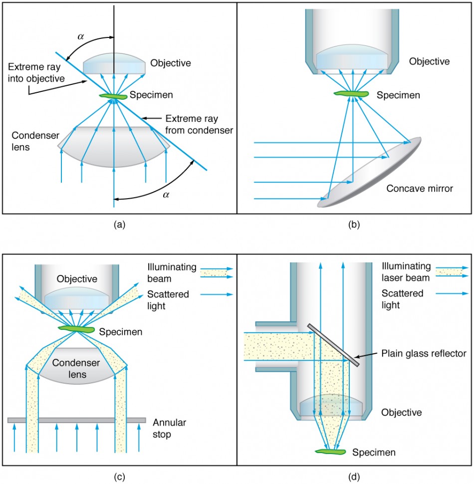
When using a microscope, we rely on gathering light to form an image. Hence most specimens need to be illuminated, particularly at higher magnifications, when observing details that are so small that they reflect only small amounts of light. To make such objects easily visible, the intensity of light falling on them needs to be increased. Special illuminating systems called condensers are used for this purpose. The type of condenser that is suitable for an application depends on how the specimen is examined, whether by transmission, scattering or reflecting. See Figure 6 for an example of each. White light sources are common and lasers are often used. Laser light illumination tends to be quite intense and it is important to ensure that the light does not result in the degradation of the specimen.
NIST Certified UV Radiometer ideal for inspecting ultraviolet light sources in a variety of quality control applications is available at Edmund Optics.
Whether in industrial automation, robotics, machine vision, surveillance, medical imaging, or any other industry, TechNexion’s C-mount and S-mount cameras offer options to meet your specific imaging requirements.
5. (a) +18.3 cm (on the eyepiece side of the objective lens); (b) −60.0; (c) −11.3 cm (on the objective side of the eyepiece); (d) +6.67; (e) −400
Although the eye is marvelous in its ability to see objects large and small, it obviously has limitations to the smallest details it can detect. Human desire to see beyond what is possible with the naked eye led to the use of optical instruments. In this section we will examine microscopes, instruments for enlarging the detail that we cannot see with the unaided eye. The microscope is a multiple-element system having more than a single lens or mirror. (See Figure 1.) A microscope can be made from two convex lenses. The image formed by the first element becomes the object for the second element. The second element forms its own image, which is the object for the third element, and so on. Ray tracing helps to visualize the image formed. If the device is composed of thin lenses and mirrors that obey the thin lens equations, then it is not difficult to describe their behavior numerically.
Gather your family and friends around our Breadboard Farmhouse Dining Table. This timeless beauty mimics our Farmhouse Plank Table but with the added design ...
by S Ivanov · 2024 · Cited by 39 — Prior studies provided valuable insights into the use of GenAI tools in different settings including the educational and research context through the lenses of ...
The term f/# in general is called the f-number and is used to denote the light per unit area reaching the image plane. In photography, an image of an object at infinity is formed at the focal point and the f-number is given by the ratio of the focal length f of the lens and the diameter D of the aperture controlling the light into the lens (see Figure 3b). If the acceptance angle is small the NA of the lens can also be used as given below.
A lens mount compatible with ultra-wide-angle lenses may be preferred in a robotics application that requires a wide-angle view. This would enable capturing a larger area without requiring extensive camera-to-subject distance.
The C-mount connection comprises an imperial thread with a one-inch diameter and 32 threads per inch. This resembles a metric thread, with dimensions comparable to M25.5 x 0.75 mm.The rear focal distances of the C-mount and CS-mount connectors are an important differentiating characteristic. C-mount connectors have a fixed rear focal distance of 17.526 mm, exactly 5 mm more than CS-mount connectors. While a CS-mount lens cannot be used directly with a C-mount camera, a C-mount lens can be used with a CS-mount camera via a CS-mount adapter, typically a 5 mm spacer ring.
Figure 6. Illumination of a specimen in a microscope. (a) Transmitted light from a condenser lens. (b) Transmitted light from a mirror condenser. (c) Dark field illumination by scattering (the illuminating beam misses the objective lens). (d) High magnification illumination with reflected light – normally laser light.
The S-mount lens system employs a screw-threaded mounting approach and finds frequent utilization in board-level cameras. This mount type encompasses a 12mm metric thread diameter with a pitch of 0.5 mm (M12x0.5), with the “M” denoting metric dimensions measured in millimeters of the outer diameter.
Compactness is critical in applications with limited space, such as a handheld retina scanner for example. When compactness is a priority, placing the sensor near the camera housing is critical.Because of their reduced size and ubiquitous availability, developers prefer S-mount lens types over C/CS-mount lenses in most embedded vision applications. Consider the use of a body-worn camera by law enforcement officials. The lens mount should be small and lightweight to provide comfort and unobtrusiveness while capturing high-quality images.
Some lens mounts provide manual or motorized focus adjustments, which can benefit applications requiring precise focusing. Choosing a lens-to-mount combination that assures the highest focus quality is essential. For instance, a lens mount compatible with motorized focus control may be chosen in a medical imaging system. This allows healthcare providers to remotely adjust the camera’s focus without physically interacting with it.
What is objective magnificationin microscope
When it comes to embedded vision technology, choosing the suitable lens mount is crucial for capturing high-quality images and unlocking the full potential of your devices.
The focal length determines the lens’s magnification and the distance at which objects come into sharp focus. It affects the field of view and the capacity to photograph subjects up close or far away. The lens’s focal length determines the type of mount with which it is compatible.
TFL (Through-Focal-Length) and TFL-II mounts are less common in embedded vision systems but have significant applications in scientific and research imaging. Due to the larger diameter of these mounts compared to the common C-mount, they are ideally suited for high-precision and resolution situations. Their primary applications include microscopy, scientific instruments, and particular industrial inspection arrangements.In contrast, the T-mount, known as the M42-mount, distinguishes itself from other mount-varieties. Sophisticated cameras predominantly employ it with large, high-resolution sensors. This mount type has a metric thread with a 42 mm diameter and 0.75 mm pitch (M42x0.75). This mount’s standard flange focal distance is 55 mm.The TFL-mount was designed for APS-C (27.9mm) sensors, which are too large for a C-mount but too small for an F-mount. The TFL-mount possesses thread dimensions of M35x0.75mm and shares the same flange distance of 17.526mm as the C-mount. The TFL-mount provides the same durability as the C-mount but accommodates larger sensors, bridging the limitations of the F-mount.


 Ms.Cici
 8618319014500