
Tube UV Gel Nail Glue - how to use uv nail glue
In order to understand the beam waist and Rayleigh range after the beam travels through the lens, it is necessary to know the magnification of the system (α), given by:
OpticLens price
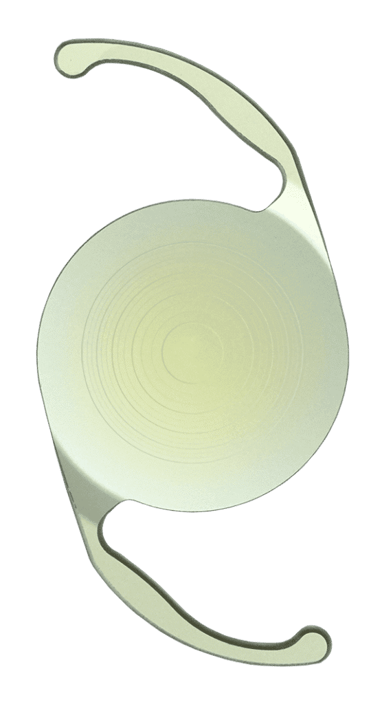
A trifocal intraocular lens is used to replace the natural lens of your eye during cataract surgery. The trifocal lens involves three different prescriptions in one lens, which helps you to have a clear vision for near, intermediate, and far distances. This can reduce your dependence on glasses or contacts and potentially eliminate it completely.

The Rayleigh range of a Gaussian beam is defined as the value of z where the cross-sectional area of the beam is doubled. This occurs when w(z) has increased to √2 w0. Using Equation 4, the Rayleigh range (zR) can be expressed as:
Optical lenses meaning
The PanOptix lens was the leading lens technology for cataract patients in more than 70 countries before it was FDA-approved. The Cleveland Eye Clinic surgeons were the first in Ohio to implant a PanOptix Trifocal IOL.
The AcrySof IQ PanOptix® Trifocal IOL is the first and only FDA-approved trifocal lens implant. The range of vision delivered by the PanOptix trifocal lens offers a considerable reduction in a patient’s need for glasses after cataract surgery. Particularly, this lens technology allows a patient to be able to see their cell phone, computer, and golf ball without glasses.
Similarly to when s << zR, the calculations for the output beam waist, divergence, Rayleigh range, and beam waist location are also simplified:
Opticlens microscope
PanOptix is the first trifocal lens in the United States, as well as the only one. The enhanced vision that is provided by them is unrivaled by any other type of lens. While other multifocal lenses only have sections for close-up and distance vision, the PanOptix trifocal lenses have sections that improve vision for distances that are near, far, and intermediate.
Where w0 is beam waist before the lens and w0’ is the beam waist after the lens. The thin lens equation for Gaussian beams can then be rewritten to include the Rayleigh range of the beam after the lens (zR'):
OpticLens Abiotic Factor
A plot of the normalized image distance (s’/f) versus the normalized object distance (s/f) shows the possible output waist locations at a given normalized Rayleigh range (zR/f) (Figure 6). This plot shows that Gaussian beams focused through a lens have a few key differences when compared to conventional thin lens imaging. Gaussian beam imaging has both minimum and maximum possible image distances, while conventional thin lens imaging does not. The maximum image distance of a refocused Gaussian beam occurs at an object distance of -(f + zR), as opposed to –f. The point on the plot where s/f is equal to -1 and s’/f is equal to 1 indicates that the output waist will be at the back focal point of the lens if the input is at the front focal point of a positive lens.
There are two limiting cases which further simplify the calculations of the output beam waist size and location: when s is much less than zR or much greater than zR.3 When the lens is well within the laser’s Rayleigh range, then s << zR and (|s| − f)2 < zR2. Equation 18 simplifies to:
Trifocal lenses are a generally more expensive option, and insurance companies tend not to cover elective parts of cataract surgery, like laser-assisted cataract surgery or the different types of lenses. So, if you choose to utilize a trifocal intraocular lens, you will need to pay out-of-pocket costs for part of the procedure. However, for many, the benefits of reducing dependence on glasses outweigh the costs.
BeachwoodOffice & Optical 25101 Chagrin Boulevard, Suite 150 Beachwood, OH 44122 Office Staff: 216-359-1734 Optical: 216-359-3002
In the above equations, λ is the wavelength of the laser and θ is a far field approximation. Therefore, θ does not accurately represent the divergence of the beam near the beam waist, but it becomes more accurate as the distance away from the beam waist increases. As seen in Equation 3, a small beam waist results in a larger divergence angle, while a large beam waist results in a smaller divergence angle (or a more collimated beam). This explains why laser beam expanders can reduce beam divergence by increasing beam diameter.
The total distance from the laser to the focused spot is calculated by adding the absolute value of s to s’. Equation 9 can also be written in a dimensionless form by multiplying both sides by f:
Optical lens manufacturers
Counterintuitively, the intensity of a focused beam in a target at a fixed distance (L) away from the lens is not maximized when the waist is located at the target. The intensity on the target is actually maximized when the waist occurs at a location before the target (Figure 10). This phenomenon is known as Gaussian focal shift.
The lengthy derivation is not covered in this text, but the beam radius at the target can be described by the following expression4:
After multiplying both sides by the denominator from the left side of the equation and then multiplying both sides by (w0')2, Equation 14 becomes:
The focused beam waist can be minimized by reducing the focal length of the lens and |s|-f. The terms next to w0 in Equation 17 are defined as another form of the magnification constant α in order to compare the values of the input beam to the output beam after going through the lens (Figure 8).3
The wavefront of the laser is planar at the beam waist and approaches that shape again as the distance from the beam waist region increases. This occurs because the radius of curvature of the wavefront begins to approach infinity. The radius of curvature of the wavefront decreases from infinity at the beam waist to a minimum value at the Rayleigh range, and then returns to infinity when it is far away from the laser (Figure 3); this is true for both sides of the beam waist.3
What are optical lenses used for
The Cleveland Eye Clinic surgeons are committed to offering the latest innovations in cataract surgery to each of our patients. Our goal is to offer our patients the best technology options, and a warm comfortable experience. The PanOptix® lens is another innovative lens option that will be an excellent option for many of our patients.
This equation approaches the standard thin lens equation as zR/f approaches 0, allowing the standard thin lens equation to be used for lenses with a long focal length. Equations 9 and 10 can be used to find the location of the beam waist after being imaged through the lens (Figure 5).
In many laser optics applications, the laser beam is assumed to be Gaussian with an irradiance profile that follows an ideal Gaussian distribution. All actual laser beams will have some deviation from ideal Gaussian behavior. The M2 factor, also known as the beam quality factor, compares the performance of a real laser beam with that of a diffraction-limited Gaussian beam.1 Gaussian irradiance profiles are symmetric around the center of the beam and decrease as the distance from the center of the beam perpendicular to the direction of propagation increases (Figure 1). This distribution is described by Equation 12:
In many applications, such as laser materials processing or surgery, it is highly important to focus a laser beam down to the smallest spot possible to maximize intensity and minimize the heated area. In cases such as these, the goal is to minimize w0' (Figure 7). A modified version of Equation 13 may be used to identify how to minimize the output beam waist3:
Many laser optics systems require manipulation of a laser beam as opposed to simply using the “raw” beam. This may be done using optical components such as lenses, mirrors, prisms, etc. Below is a guide to some of the most common manipulations of Gaussian beams.
Differentiating Equation 34 with respect to the focal length of the focusing lens (f) and solving for f when d⁄df [wL (f )] = 0 reveals the lens focal length resulting in the minimum beam radius, and therefore highest intensity, at the target.

Moreover, the technology of the PanOptix lens offers patients the broadest range of vision all in one lens compared to any other cataract lens implant in the US. The PanOptix® trifocal lens was developed using ENLIGHTEN® Optical Technology. ENLIGHTEN® Optical Technology optimizes intermediate vision without compromising the quality of near and distance vision. Additionally, the PanOptix® lens is designed to help patients who have astigmatism, as well as those who do not.
The Cleveland Eye Clinic takes almost every type of insurance. We also offer convenient patient financing programs to help patients with out-of-pocket fees. A Cleveland Eye Clinic counselor can help you to be approved. It only takes minutes!
As |s| approaches either zero or infinity, d⁄df [wL (f )] = 0 when f = L. In both of these cases, the input beam is approximately collimated, and it thereby follows that the smallest beam radius would occur at the focal point of the lens.
In Equation 7, s’ is the distance from the lens to the image, s is the distance from the lens to the object, and f is the focal length of the lens. If the object and image are at opposite sides of the lens, s is a negative value and s’ is a positive value. This equation ignores the thickness of a real lens and is therefore only a simple approximation of real behavior (Figure 4). The thin lens equation can also be written in a dimensionless form by multiplying both sides of the equation by f:
OpticLens abiotic factor trade
The above equation will break down if the lens is at the beam waist (s=0). The inverse of the squared magnification constant can be used to relate the beam waist sizes and locations3:
The other limiting situation where the lens is far outside of the Rayleigh range and s >> zR, simplifying Equation 18 to:
However, this irradiance profile does not stay constant as the beam propagates through space, hence the dependence of w(z) on z. Due to diffraction, a Gaussian beam will converge and diverge from an area called the beam waist (w0), which is where the beam diameter reaches a minimum value. The beam converges and diverges equally on both sides of the beam waist by the divergence angle θ (Figure 2). The beam waist and divergence angle are both measured from the axis and their relationship can be seen in Equation 2 and Equation 32:
Please select your shipping country to view the most accurate inventory information, and to determine the correct Edmund Optics sales office for your order.
Cataract patients now have an option to see at both near and far distances after cataract surgery! NEW multi-focal IOL technology can now decrease dependence on glasses after surgery.
Furthermore, based on the FDA study, over 99% of patients who receive the PanOptix® lens would choose the same lens again. This level of patient satisfaction with the PanOptix® lens illustrates the value this technology has brought.
In Equation 1, I0 is the peak irradiance at the center of the beam, r is the radial distance away from the axis, w(z) is the radius of the laser beam where the irradiance is 1/e2 (13.5%) of I0, z is the distance propagated from the plane where the wavefront is flat, and P is the total power of the beam.
Opticlens eye
Achieving a truly collimated beam where the divergence is 0 is not possible, but achieving an approximately collimated beam by either minimizing the divergence or maximizing the distance between the point of observation and the nearest beam waist is possible. Since the output divergence is inversely proportional to the magnification constant α, the output divergence reaches a minimum value when |s| = f (Figure 11).
Both of these results intuitively make sense because the beam’s wavefront is approximately planar both at and very far away from the beam waist. At these locations, the beam is almost perfectly collimated (Figure 9). According to the standard thin lens equation, a collimated input would have an image distance equal to the focal length of the lens.
In addition to describing imaging applications, the thin lens equation is applicable to the focusing of a Gaussian beam by treating the waist of the input beam as the object and the waist of the output beam as the image. Gaussian beams remain Gaussian after passing through an ideal lens with no aberrations. In 1983, Sidney Self developed a version of the thin lens equation that took Gaussian propagation into account4:


 Ms.Cici
 8618319014500