
Transfem Guide - mtf wiki
In late 1982, he read an article from IBM Laboratories, published in Laser Focus, describing the photo-ablative properties of an excimer laser on organic material. This was very exciting information, but, unfortunately, Peyman did not have access to this laser, which at the time was new and very expensive. By 1985 and beyond, many investigators were interested in ablating the corneal surface. However, because of his previous experience with the CO2 laser, Peyman wanted to avoid surface ablation in order to prevent potential corneal scarring and the pain associated with the removal of the corneal epithelium, necessary to expose the surface of the cornea. Therefore, in July 1985, he applied for a patent that described a method of modifying corneal refractive errors using laser ablation under a corneal flap. This US patent was accepted after two revisions and issued in June, 1989. Peyman performed a number of experimental studies evaluating the effect of various excimer lasers in collaboration with Physics Department of the University of Helsinki, Finland. Since he had purchased an Erb-Yag laser in the U.S., he evaluated the concept using this laser in vivo in rabbit and primate eyes and described the creation of a hinged corneal flap to enable the ablation to be performed on the exposed corneal bed, thus reducing the potential for postoperative scarring and pain.[5]
Barreldistortion correction
However, their ablation was not predictable. In October 2009, Peyman invented and applied for a patent on a method of preventing corneal implant rejection, which was approved in 2017 (US Patent 9,681,942). It consisted of forming a Lasik flap in the cornea, raising the flap, inserting a lamellar cornea under the flap so as to overlie the exposed stromal tissue. The inlay is ablated with wavefront guided excimer laser, to correct the refractive errors of the eye, applying a cross linking solution to the inlay and stromal tissue of the cornea, replacing the corneal flap and cross linking the inlay with UV radiation, killing the cellular elements in the inlay and its surrounding cornea, preventing cellular migration in the inlay and its rejection or encapsulation by the host corneal cells. This new procedure is now called “Mesoick” (Meso means Inside, Implant, Crosslinking Keratomileusis (US Patent 9,037,033). This creates an immune privileged cell free space that does not initiate an immune response to an implant. A synthetic, crosslinked organic or polymeric lens can be implanted in the corneal pocket to compensate for the patient's refractive error. The implant can be exchanged as the eye grows or refractive need dictates.[7]
How can this problem be solved? Significant research is being done in this area, and the possible solutions involve different optical systems and display technologies. For example, digital light processing (DLP) technology directly projects light into the eye without using lenses. Another way to greatly reduce this problem is to use a Fresnel lens (see Figure 7.14), which more accurately controls the bending of light rays by using a corrugated or sawtooth surface over a larger area; an aspheric design can be implemented as well. A Fresnel lens is used, for example, in the HTC Vive VR headset. One unfortunate side effect of Fresnel lenses is that glaring can be frequently observed as light scatters across the ridges along the surface. Whether small or large, the distortion can also be corrected in software. One assumption is that the distortion is circularly symmetric. This means that the amount of distortion depends only on the distance from the lens center, and not the particular direction from the center. Even if the lens distortion is perfectly circularly symmetric, it must also be placed so that it is centered over the eye. Some headsets offer IPD adjustment, which allows the distance between the lenses to be adjusted so that they are matched to the user's eyes. If the eye is not centered on the lens, then asymmetric distortion arises. The situation is not perfect because as the eye rotates, the pupil moves along a spherical arc. As the position of the pupil over the lens changes laterally, the distortion varies and becomes asymmetric. This motivates making the lens as large as possible so that this problem is reduced. Another factor is that the distortion will change as the distance between the lens and the screen is altered. This adjustment may be useful to accommodate users with nearsightedness or farsightedness, as done in the Samsung Gear VR headset. The adjustment is also common in binoculars and binoculars, which explains why many people do not need their glasses to use them. To handle distortion correctly, the headset should ideally sense the adjustment setting and take it into account. To fix radially symmetric distortion, suppose that the transformation chain has been applied to the geometry, resulting in the canonical view volume, as covered in Section 3.5. All points that were inside of the viewing frustum now have and coordinates ranging from to . Consider referring to these points using polar coordinates : (7.15) in which represents the inverse tangent of . This function is commonly used in programming languages to return an angle over the entire range from 0 to . (The arctangent alone cannot do this because the quadrant that came from is needed.) We now express the lens distortion in terms of transforming the radius , without affecting the direction (because of symmetry). Let denote a function that applies to positive real numbers and distorts the radius. Let denote the undistorted radius, and let denote the distorted radius. Both pincushion and barrel distortion are commonly approximated using polynomials with odd powers, resulting in being defined as (7.16) in which and are suitably chosen constants. If , then barrel distortion occurs. If , then pincushion distortion results. Higher-order polynomials could also be used, such as adding a term on the right above; however, in practice this is often considered unnecessary. Correcting the distortion involves two phases: Determine the radial distortion function for a particular headset, which involves a particular lens placed at a fixed distance from the screen. This is a regression or curve-fitting problem that involves an experimental setup that measures the distortion of many points and selects the coefficients , , and so on, that provide the best fit. Determine the inverse of so that it be applied to the rendered image before the lens causes its distortion. The composition of the inverse with should cancel out the distortion function. Unfortunately, polynomial functions generally do not have inverses that can be determined or even expressed in a closed form. Therefore, approximations are used. One commonly used approximation is [119]: (7.17) Alternatively, the inverse can be calculated very accurately off-line and then stored in an array for fast access. It needs to be done only once per headset design. Linear interpolation can be used for improved accuracy. The inverse values can be accurately calculated using Newton's method, with initial guesses provided by simply plotting against and swapping the axes. Figure 7.15: The rendered image appears to have a barrel distortion. Note that the resolution is effectively dropped near the periphery. (Figure by Nvidia.) The transformation could be worked directly into the perspective transformation, thereby replacing and with a nonlinear operation. By leveraging the existing graphics rendering pipeline, it is instead handled as a post-processing step. The process of transforming the image is sometimes called distortion shading because it can be implemented as a shading operation in the GPU; it has nothing to do with ``shading'' as defined in Section 7.1. The rasterized image that was calculated using methods in Section 7.2 can be converted into a transformed image using (7.17), or another representation of , on a pixel-by-pixel basis. If compensating for a pincushion distortion, the resulting image will appear to have a barrel distortion; see Figure 7.15. To improve VR performance, multiresolution shading is used in Nvidia GTX 1080 GPUs. One problem is that the resolution is effectively dropped near the periphery because of the transformed image (Figure 7.15). This results in wasted shading calculations in the original image. Instead, the image can be rendered before the transformation by taking into account the final resulting resolutions after the transformation. A lower-resolution image is rendered in a region that will become compressed by the transformation. The methods described in this section may also be used for other optical distortions that are radially symmetric. For example, chromatic aberration can be partially corrected by transforming the red, green, and blue subpixels differently. Each color is displaced radially by a different amount to compensate for the radial distortion that occurs based on its wavelength. If chromatic aberration correction is being used, then if the lenses are removed from the VR headset, it would become clear that the colors are not perfectly aligned in the images being rendered to the display. The rendering system must create a distortion of pixel placements on the basis of color so that they will be moved closer to the correct places after they pass through the lens. Next: 7.4 Improving Latency and Up: 7. Visual Rendering Previous: VR-specific rasterization problems Contents Index Steven M LaValle 2020-11-11
The transformation could be worked directly into the perspective transformation, thereby replacing and with a nonlinear operation. By leveraging the existing graphics rendering pipeline, it is instead handled as a post-processing step. The process of transforming the image is sometimes called distortion shading because it can be implemented as a shading operation in the GPU; it has nothing to do with ``shading'' as defined in Section 7.1. The rasterized image that was calculated using methods in Section 7.2 can be converted into a transformed image using (7.17), or another representation of , on a pixel-by-pixel basis. If compensating for a pincushion distortion, the resulting image will appear to have a barrel distortion; see Figure 7.15. To improve VR performance, multiresolution shading is used in Nvidia GTX 1080 GPUs. One problem is that the resolution is effectively dropped near the periphery because of the transformed image (Figure 7.15). This results in wasted shading calculations in the original image. Instead, the image can be rendered before the transformation by taking into account the final resulting resolutions after the transformation. A lower-resolution image is rendered in a region that will become compressed by the transformation. The methods described in this section may also be used for other optical distortions that are radially symmetric. For example, chromatic aberration can be partially corrected by transforming the red, green, and blue subpixels differently. Each color is displaced radially by a different amount to compensate for the radial distortion that occurs based on its wavelength. If chromatic aberration correction is being used, then if the lenses are removed from the VR headset, it would become clear that the colors are not perfectly aligned in the images being rendered to the display. The rendering system must create a distortion of pixel placements on the basis of color so that they will be moved closer to the correct places after they pass through the lens. Next: 7.4 Improving Latency and Up: 7. Visual Rendering Previous: VR-specific rasterization problems Contents Index Steven M LaValle 2020-11-11
Always aware of the potential limitations of his invention, Peyman devoted considerable time and effort in subsequent years to ameliorating them. In order to improve the risk/benefit considerations of the LASIK procedure, he invented in 2004 and patented a broad range of ablative and non-ablative inlays to be placed under the surgically created corneal flap (US Patent 6,702,807). These inlays offered many potential advantages over the standard LASIK technique, the most significant of which is that the inlay procedure is reversible.[6]
Whether small or large, the distortion can also be corrected in software. One assumption is that the distortion is circularly symmetric. This means that the amount of distortion depends only on the distance from the lens center, and not the particular direction from the center. Even if the lens distortion is perfectly circularly symmetric, it must also be placed so that it is centered over the eye. Some headsets offer IPD adjustment, which allows the distance between the lenses to be adjusted so that they are matched to the user's eyes. If the eye is not centered on the lens, then asymmetric distortion arises. The situation is not perfect because as the eye rotates, the pupil moves along a spherical arc. As the position of the pupil over the lens changes laterally, the distortion varies and becomes asymmetric. This motivates making the lens as large as possible so that this problem is reduced. Another factor is that the distortion will change as the distance between the lens and the screen is altered. This adjustment may be useful to accommodate users with nearsightedness or farsightedness, as done in the Samsung Gear VR headset. The adjustment is also common in binoculars and binoculars, which explains why many people do not need their glasses to use them. To handle distortion correctly, the headset should ideally sense the adjustment setting and take it into account. To fix radially symmetric distortion, suppose that the transformation chain has been applied to the geometry, resulting in the canonical view volume, as covered in Section 3.5. All points that were inside of the viewing frustum now have and coordinates ranging from to . Consider referring to these points using polar coordinates : (7.15) in which represents the inverse tangent of . This function is commonly used in programming languages to return an angle over the entire range from 0 to . (The arctangent alone cannot do this because the quadrant that came from is needed.) We now express the lens distortion in terms of transforming the radius , without affecting the direction (because of symmetry). Let denote a function that applies to positive real numbers and distorts the radius. Let denote the undistorted radius, and let denote the distorted radius. Both pincushion and barrel distortion are commonly approximated using polynomials with odd powers, resulting in being defined as (7.16) in which and are suitably chosen constants. If , then barrel distortion occurs. If , then pincushion distortion results. Higher-order polynomials could also be used, such as adding a term on the right above; however, in practice this is often considered unnecessary. Correcting the distortion involves two phases: Determine the radial distortion function for a particular headset, which involves a particular lens placed at a fixed distance from the screen. This is a regression or curve-fitting problem that involves an experimental setup that measures the distortion of many points and selects the coefficients , , and so on, that provide the best fit. Determine the inverse of so that it be applied to the rendered image before the lens causes its distortion. The composition of the inverse with should cancel out the distortion function. Unfortunately, polynomial functions generally do not have inverses that can be determined or even expressed in a closed form. Therefore, approximations are used. One commonly used approximation is [119]: (7.17) Alternatively, the inverse can be calculated very accurately off-line and then stored in an array for fast access. It needs to be done only once per headset design. Linear interpolation can be used for improved accuracy. The inverse values can be accurately calculated using Newton's method, with initial guesses provided by simply plotting against and swapping the axes. Figure 7.15: The rendered image appears to have a barrel distortion. Note that the resolution is effectively dropped near the periphery. (Figure by Nvidia.) The transformation could be worked directly into the perspective transformation, thereby replacing and with a nonlinear operation. By leveraging the existing graphics rendering pipeline, it is instead handled as a post-processing step. The process of transforming the image is sometimes called distortion shading because it can be implemented as a shading operation in the GPU; it has nothing to do with ``shading'' as defined in Section 7.1. The rasterized image that was calculated using methods in Section 7.2 can be converted into a transformed image using (7.17), or another representation of , on a pixel-by-pixel basis. If compensating for a pincushion distortion, the resulting image will appear to have a barrel distortion; see Figure 7.15. To improve VR performance, multiresolution shading is used in Nvidia GTX 1080 GPUs. One problem is that the resolution is effectively dropped near the periphery because of the transformed image (Figure 7.15). This results in wasted shading calculations in the original image. Instead, the image can be rendered before the transformation by taking into account the final resulting resolutions after the transformation. A lower-resolution image is rendered in a region that will become compressed by the transformation. The methods described in this section may also be used for other optical distortions that are radially symmetric. For example, chromatic aberration can be partially corrected by transforming the red, green, and blue subpixels differently. Each color is displaced radially by a different amount to compensate for the radial distortion that occurs based on its wavelength. If chromatic aberration correction is being used, then if the lenses are removed from the VR headset, it would become clear that the colors are not perfectly aligned in the images being rendered to the display. The rendering system must create a distortion of pixel placements on the basis of color so that they will be moved closer to the correct places after they pass through the lens. Next: 7.4 Improving Latency and Up: 7. Visual Rendering Previous: VR-specific rasterization problems Contents Index Steven M LaValle 2020-11-11
Peyman has been granted 200 US Patents[8] covering a broad range of novel medical devices, intra-ocular drug delivery, surgical techniques, as well as new methods of diagnosis and treatment.
Optical distortion correctionsoftware
Peyman held a joint appointment at the School of Medicine and also at the Neuroscience Center of Excellence at the Louisiana State University Medical University Medical Center in New Orleans during 1987–2000. During 1998-2000 Peyman held the Prince Abdul Aziz Bin Ahmed Bin Abdul Aziz Al Saud Chair in Retinal Diseases. During 2000–2006, Peyman served as professor of ophthalmology, ocular oncology and co-director, Vitreo-Retinal Service, Tulane University School of Medicine in New Orleans.[citation needed]
Optical distortionmeaning
Correcting the distortion involves two phases: Determine the radial distortion function for a particular headset, which involves a particular lens placed at a fixed distance from the screen. This is a regression or curve-fitting problem that involves an experimental setup that measures the distortion of many points and selects the coefficients , , and so on, that provide the best fit. Determine the inverse of so that it be applied to the rendered image before the lens causes its distortion. The composition of the inverse with should cancel out the distortion function. Unfortunately, polynomial functions generally do not have inverses that can be determined or even expressed in a closed form. Therefore, approximations are used. One commonly used approximation is [119]: (7.17) Alternatively, the inverse can be calculated very accurately off-line and then stored in an array for fast access. It needs to be done only once per headset design. Linear interpolation can be used for improved accuracy. The inverse values can be accurately calculated using Newton's method, with initial guesses provided by simply plotting against and swapping the axes. Figure 7.15: The rendered image appears to have a barrel distortion. Note that the resolution is effectively dropped near the periphery. (Figure by Nvidia.) The transformation could be worked directly into the perspective transformation, thereby replacing and with a nonlinear operation. By leveraging the existing graphics rendering pipeline, it is instead handled as a post-processing step. The process of transforming the image is sometimes called distortion shading because it can be implemented as a shading operation in the GPU; it has nothing to do with ``shading'' as defined in Section 7.1. The rasterized image that was calculated using methods in Section 7.2 can be converted into a transformed image using (7.17), or another representation of , on a pixel-by-pixel basis. If compensating for a pincushion distortion, the resulting image will appear to have a barrel distortion; see Figure 7.15. To improve VR performance, multiresolution shading is used in Nvidia GTX 1080 GPUs. One problem is that the resolution is effectively dropped near the periphery because of the transformed image (Figure 7.15). This results in wasted shading calculations in the original image. Instead, the image can be rendered before the transformation by taking into account the final resulting resolutions after the transformation. A lower-resolution image is rendered in a region that will become compressed by the transformation. The methods described in this section may also be used for other optical distortions that are radially symmetric. For example, chromatic aberration can be partially corrected by transforming the red, green, and blue subpixels differently. Each color is displaced radially by a different amount to compensate for the radial distortion that occurs based on its wavelength. If chromatic aberration correction is being used, then if the lenses are removed from the VR headset, it would become clear that the colors are not perfectly aligned in the images being rendered to the display. The rendering system must create a distortion of pixel placements on the basis of color so that they will be moved closer to the correct places after they pass through the lens. Next: 7.4 Improving Latency and Up: 7. Visual Rendering Previous: VR-specific rasterization problems Contents Index Steven M LaValle 2020-11-11
We now express the lens distortion in terms of transforming the radius , without affecting the direction (because of symmetry). Let denote a function that applies to positive real numbers and distorts the radius. Let denote the undistorted radius, and let denote the distorted radius. Both pincushion and barrel distortion are commonly approximated using polynomials with odd powers, resulting in being defined as (7.16) in which and are suitably chosen constants. If , then barrel distortion occurs. If , then pincushion distortion results. Higher-order polynomials could also be used, such as adding a term on the right above; however, in practice this is often considered unnecessary. Correcting the distortion involves two phases: Determine the radial distortion function for a particular headset, which involves a particular lens placed at a fixed distance from the screen. This is a regression or curve-fitting problem that involves an experimental setup that measures the distortion of many points and selects the coefficients , , and so on, that provide the best fit. Determine the inverse of so that it be applied to the rendered image before the lens causes its distortion. The composition of the inverse with should cancel out the distortion function. Unfortunately, polynomial functions generally do not have inverses that can be determined or even expressed in a closed form. Therefore, approximations are used. One commonly used approximation is [119]: (7.17) Alternatively, the inverse can be calculated very accurately off-line and then stored in an array for fast access. It needs to be done only once per headset design. Linear interpolation can be used for improved accuracy. The inverse values can be accurately calculated using Newton's method, with initial guesses provided by simply plotting against and swapping the axes. Figure 7.15: The rendered image appears to have a barrel distortion. Note that the resolution is effectively dropped near the periphery. (Figure by Nvidia.) The transformation could be worked directly into the perspective transformation, thereby replacing and with a nonlinear operation. By leveraging the existing graphics rendering pipeline, it is instead handled as a post-processing step. The process of transforming the image is sometimes called distortion shading because it can be implemented as a shading operation in the GPU; it has nothing to do with ``shading'' as defined in Section 7.1. The rasterized image that was calculated using methods in Section 7.2 can be converted into a transformed image using (7.17), or another representation of , on a pixel-by-pixel basis. If compensating for a pincushion distortion, the resulting image will appear to have a barrel distortion; see Figure 7.15. To improve VR performance, multiresolution shading is used in Nvidia GTX 1080 GPUs. One problem is that the resolution is effectively dropped near the periphery because of the transformed image (Figure 7.15). This results in wasted shading calculations in the original image. Instead, the image can be rendered before the transformation by taking into account the final resulting resolutions after the transformation. A lower-resolution image is rendered in a region that will become compressed by the transformation. The methods described in this section may also be used for other optical distortions that are radially symmetric. For example, chromatic aberration can be partially corrected by transforming the red, green, and blue subpixels differently. Each color is displaced radially by a different amount to compensate for the radial distortion that occurs based on its wavelength. If chromatic aberration correction is being used, then if the lenses are removed from the VR headset, it would become clear that the colors are not perfectly aligned in the images being rendered to the display. The rendering system must create a distortion of pixel placements on the basis of color so that they will be moved closer to the correct places after they pass through the lens. Next: 7.4 Improving Latency and Up: 7. Visual Rendering Previous: VR-specific rasterization problems Contents Index Steven M LaValle 2020-11-11
Peyman is currently professor of basic medical sciences at the University of Arizona College of Medicine – Phoenix & Optical engineering at the University of Arizona in Tucson. Peyman was awarded in 2013 an honoree doctorate degree from the National University of Cordoba in Argentina.[3]
Optical distortion correctionformula
Figure 7.15: The rendered image appears to have a barrel distortion. Note that the resolution is effectively dropped near the periphery. (Figure by Nvidia.) The transformation could be worked directly into the perspective transformation, thereby replacing and with a nonlinear operation. By leveraging the existing graphics rendering pipeline, it is instead handled as a post-processing step. The process of transforming the image is sometimes called distortion shading because it can be implemented as a shading operation in the GPU; it has nothing to do with ``shading'' as defined in Section 7.1. The rasterized image that was calculated using methods in Section 7.2 can be converted into a transformed image using (7.17), or another representation of , on a pixel-by-pixel basis. If compensating for a pincushion distortion, the resulting image will appear to have a barrel distortion; see Figure 7.15. To improve VR performance, multiresolution shading is used in Nvidia GTX 1080 GPUs. One problem is that the resolution is effectively dropped near the periphery because of the transformed image (Figure 7.15). This results in wasted shading calculations in the original image. Instead, the image can be rendered before the transformation by taking into account the final resulting resolutions after the transformation. A lower-resolution image is rendered in a region that will become compressed by the transformation. The methods described in this section may also be used for other optical distortions that are radially symmetric. For example, chromatic aberration can be partially corrected by transforming the red, green, and blue subpixels differently. Each color is displaced radially by a different amount to compensate for the radial distortion that occurs based on its wavelength. If chromatic aberration correction is being used, then if the lenses are removed from the VR headset, it would become clear that the colors are not perfectly aligned in the images being rendered to the display. The rendering system must create a distortion of pixel placements on the basis of color so that they will be moved closer to the correct places after they pass through the lens. Next: 7.4 Improving Latency and Up: 7. Visual Rendering Previous: VR-specific rasterization problems Contents Index Steven M LaValle 2020-11-11
The methods described in this section may also be used for other optical distortions that are radially symmetric. For example, chromatic aberration can be partially corrected by transforming the red, green, and blue subpixels differently. Each color is displaced radially by a different amount to compensate for the radial distortion that occurs based on its wavelength. If chromatic aberration correction is being used, then if the lenses are removed from the VR headset, it would become clear that the colors are not perfectly aligned in the images being rendered to the display. The rendering system must create a distortion of pixel placements on the basis of color so that they will be moved closer to the correct places after they pass through the lens. Next: 7.4 Improving Latency and Up: 7. Visual Rendering Previous: VR-specific rasterization problems Contents Index Steven M LaValle 2020-11-11
LensdistortionExamples
Hazard Statements: H301 Toxic if swallowed, H315 Causes skin irritation, H319 Causes serious eye irritation, H335 May cause respiratory irritation.
Eyepiece Tube holds the eyepieces in place above the objective lens. Binocular microscope heads typically incorporate a diopter adjustment ring that allows for ...
Next: 7.4 Improving Latency and Up: 7. Visual Rendering Previous: VR-specific rasterization problems Contents Index Steven M LaValle 2020-11-11
Peyman was born in Shiraz, Iran. At the age of 19, he moved to Germany to begin his medical studies. He received his MD at the University of Freiburg in 1962.[citation needed] He completed his internship at St. Johannes Hospital in Duisburg, Germany in 1964 and at Passaic General Hospital in Passaic, New Jersey in 1965.[citation needed] Peyman completed his residency in ophthalmology and a retina fellowship at the University of Essen, Essen Germany, in 1969 and an additional postdoctoral fellowship in retina at the Jules Stein Eye Institute, UCLA School of Medicine in Los Angeles in 1971. Peyman held the position of assistant professor of ophthalmology at the UCLA School of Medicine from 1971 and served as associate professor and then professor of ophthalmology and ocular oncology at the Illinois Eye and Ear Infirmary, University of Illinois at Chicago during 1971–1987.[citation needed]
Next: 7.4 Improving Latency and Up: 7. Visual Rendering Previous: VR-specific rasterization problems Contents Index Steven M LaValle 2020-11-11
Among other awards and honors, Peyman has received the National Medal of Technology and Innovation (2012),[18] the Waring Medal of the Journal of Refractive Surgery (2008),[19] and the American Academy of Ophthalmology's Lifetime Achievement Award (2008)[20] He was named a fellow of the National Academy of Inventors in 2013.[21]
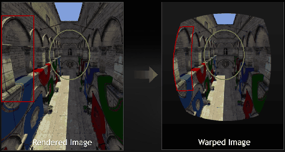
Recall from Section 4.3 that barrel and pincushion distortions are common for an optical system with a high field of view (Figure 4.20). When looking through the lens of a VR headset, a pincushion distortion typically results. If the images are drawn on the screen without any correction, then the virtual world appears to be incorrectly warped. If the user yaws his head back and forth, then fixed lines in the world, such as walls, appear to dynamically change their curvature because the distortion in the periphery is much stronger than in the center. If it is not corrected, then the perception of stationarity will fail because static objects should not appear to be warping dynamically. Furthermore, contributions may be made to VR sickness because incorrect accelerations are being visually perceived near the periphery. Figure 7.14: A Fresnel lens (pronounced like ``frenelle'') simulates a simple lens by making a corrugated surface. The convex surface on the top lens is implemented in the Fresnel lens shown on the bottom. (Figure by Piotr Kozurno.) How can this problem be solved? Significant research is being done in this area, and the possible solutions involve different optical systems and display technologies. For example, digital light processing (DLP) technology directly projects light into the eye without using lenses. Another way to greatly reduce this problem is to use a Fresnel lens (see Figure 7.14), which more accurately controls the bending of light rays by using a corrugated or sawtooth surface over a larger area; an aspheric design can be implemented as well. A Fresnel lens is used, for example, in the HTC Vive VR headset. One unfortunate side effect of Fresnel lenses is that glaring can be frequently observed as light scatters across the ridges along the surface. Whether small or large, the distortion can also be corrected in software. One assumption is that the distortion is circularly symmetric. This means that the amount of distortion depends only on the distance from the lens center, and not the particular direction from the center. Even if the lens distortion is perfectly circularly symmetric, it must also be placed so that it is centered over the eye. Some headsets offer IPD adjustment, which allows the distance between the lenses to be adjusted so that they are matched to the user's eyes. If the eye is not centered on the lens, then asymmetric distortion arises. The situation is not perfect because as the eye rotates, the pupil moves along a spherical arc. As the position of the pupil over the lens changes laterally, the distortion varies and becomes asymmetric. This motivates making the lens as large as possible so that this problem is reduced. Another factor is that the distortion will change as the distance between the lens and the screen is altered. This adjustment may be useful to accommodate users with nearsightedness or farsightedness, as done in the Samsung Gear VR headset. The adjustment is also common in binoculars and binoculars, which explains why many people do not need their glasses to use them. To handle distortion correctly, the headset should ideally sense the adjustment setting and take it into account. To fix radially symmetric distortion, suppose that the transformation chain has been applied to the geometry, resulting in the canonical view volume, as covered in Section 3.5. All points that were inside of the viewing frustum now have and coordinates ranging from to . Consider referring to these points using polar coordinates : (7.15) in which represents the inverse tangent of . This function is commonly used in programming languages to return an angle over the entire range from 0 to . (The arctangent alone cannot do this because the quadrant that came from is needed.) We now express the lens distortion in terms of transforming the radius , without affecting the direction (because of symmetry). Let denote a function that applies to positive real numbers and distorts the radius. Let denote the undistorted radius, and let denote the distorted radius. Both pincushion and barrel distortion are commonly approximated using polynomials with odd powers, resulting in being defined as (7.16) in which and are suitably chosen constants. If , then barrel distortion occurs. If , then pincushion distortion results. Higher-order polynomials could also be used, such as adding a term on the right above; however, in practice this is often considered unnecessary. Correcting the distortion involves two phases: Determine the radial distortion function for a particular headset, which involves a particular lens placed at a fixed distance from the screen. This is a regression or curve-fitting problem that involves an experimental setup that measures the distortion of many points and selects the coefficients , , and so on, that provide the best fit. Determine the inverse of so that it be applied to the rendered image before the lens causes its distortion. The composition of the inverse with should cancel out the distortion function. Unfortunately, polynomial functions generally do not have inverses that can be determined or even expressed in a closed form. Therefore, approximations are used. One commonly used approximation is [119]: (7.17) Alternatively, the inverse can be calculated very accurately off-line and then stored in an array for fast access. It needs to be done only once per headset design. Linear interpolation can be used for improved accuracy. The inverse values can be accurately calculated using Newton's method, with initial guesses provided by simply plotting against and swapping the axes. Figure 7.15: The rendered image appears to have a barrel distortion. Note that the resolution is effectively dropped near the periphery. (Figure by Nvidia.) The transformation could be worked directly into the perspective transformation, thereby replacing and with a nonlinear operation. By leveraging the existing graphics rendering pipeline, it is instead handled as a post-processing step. The process of transforming the image is sometimes called distortion shading because it can be implemented as a shading operation in the GPU; it has nothing to do with ``shading'' as defined in Section 7.1. The rasterized image that was calculated using methods in Section 7.2 can be converted into a transformed image using (7.17), or another representation of , on a pixel-by-pixel basis. If compensating for a pincushion distortion, the resulting image will appear to have a barrel distortion; see Figure 7.15. To improve VR performance, multiresolution shading is used in Nvidia GTX 1080 GPUs. One problem is that the resolution is effectively dropped near the periphery because of the transformed image (Figure 7.15). This results in wasted shading calculations in the original image. Instead, the image can be rendered before the transformation by taking into account the final resulting resolutions after the transformation. A lower-resolution image is rendered in a region that will become compressed by the transformation. The methods described in this section may also be used for other optical distortions that are radially symmetric. For example, chromatic aberration can be partially corrected by transforming the red, green, and blue subpixels differently. Each color is displaced radially by a different amount to compensate for the radial distortion that occurs based on its wavelength. If chromatic aberration correction is being used, then if the lenses are removed from the VR headset, it would become clear that the colors are not perfectly aligned in the images being rendered to the display. The rendering system must create a distortion of pixel placements on the basis of color so that they will be moved closer to the correct places after they pass through the lens. Next: 7.4 Improving Latency and Up: 7. Visual Rendering Previous: VR-specific rasterization problems Contents Index Steven M LaValle 2020-11-11
Pincushiondistortion
Aug 28, 2022 — where d is the atomic spacing, αʹ and α are the angles of the diffracted and incident wave with the row of atoms, n is the order of diffraction, ...
Gholam A. Peyman (born 1 January 1937) is an Iranian American ophthalmologist, retina surgeon, and inventor. He is best known for his invention of LASIK eye surgery,[2] a vision correction procedure designed to allow people to see clearly without glasses. He was awarded the first US patent for the procedure in 1989.
Lensdistortion correctionalgorithm
To fix radially symmetric distortion, suppose that the transformation chain has been applied to the geometry, resulting in the canonical view volume, as covered in Section 3.5. All points that were inside of the viewing frustum now have and coordinates ranging from to . Consider referring to these points using polar coordinates : (7.15) in which represents the inverse tangent of . This function is commonly used in programming languages to return an angle over the entire range from 0 to . (The arctangent alone cannot do this because the quadrant that came from is needed.) We now express the lens distortion in terms of transforming the radius , without affecting the direction (because of symmetry). Let denote a function that applies to positive real numbers and distorts the radius. Let denote the undistorted radius, and let denote the distorted radius. Both pincushion and barrel distortion are commonly approximated using polynomials with odd powers, resulting in being defined as (7.16) in which and are suitably chosen constants. If , then barrel distortion occurs. If , then pincushion distortion results. Higher-order polynomials could also be used, such as adding a term on the right above; however, in practice this is often considered unnecessary. Correcting the distortion involves two phases: Determine the radial distortion function for a particular headset, which involves a particular lens placed at a fixed distance from the screen. This is a regression or curve-fitting problem that involves an experimental setup that measures the distortion of many points and selects the coefficients , , and so on, that provide the best fit. Determine the inverse of so that it be applied to the rendered image before the lens causes its distortion. The composition of the inverse with should cancel out the distortion function. Unfortunately, polynomial functions generally do not have inverses that can be determined or even expressed in a closed form. Therefore, approximations are used. One commonly used approximation is [119]: (7.17) Alternatively, the inverse can be calculated very accurately off-line and then stored in an array for fast access. It needs to be done only once per headset design. Linear interpolation can be used for improved accuracy. The inverse values can be accurately calculated using Newton's method, with initial guesses provided by simply plotting against and swapping the axes. Figure 7.15: The rendered image appears to have a barrel distortion. Note that the resolution is effectively dropped near the periphery. (Figure by Nvidia.) The transformation could be worked directly into the perspective transformation, thereby replacing and with a nonlinear operation. By leveraging the existing graphics rendering pipeline, it is instead handled as a post-processing step. The process of transforming the image is sometimes called distortion shading because it can be implemented as a shading operation in the GPU; it has nothing to do with ``shading'' as defined in Section 7.1. The rasterized image that was calculated using methods in Section 7.2 can be converted into a transformed image using (7.17), or another representation of , on a pixel-by-pixel basis. If compensating for a pincushion distortion, the resulting image will appear to have a barrel distortion; see Figure 7.15. To improve VR performance, multiresolution shading is used in Nvidia GTX 1080 GPUs. One problem is that the resolution is effectively dropped near the periphery because of the transformed image (Figure 7.15). This results in wasted shading calculations in the original image. Instead, the image can be rendered before the transformation by taking into account the final resulting resolutions after the transformation. A lower-resolution image is rendered in a region that will become compressed by the transformation. The methods described in this section may also be used for other optical distortions that are radially symmetric. For example, chromatic aberration can be partially corrected by transforming the red, green, and blue subpixels differently. Each color is displaced radially by a different amount to compensate for the radial distortion that occurs based on its wavelength. If chromatic aberration correction is being used, then if the lenses are removed from the VR headset, it would become clear that the colors are not perfectly aligned in the images being rendered to the display. The rendering system must create a distortion of pixel placements on the basis of color so that they will be moved closer to the correct places after they pass through the lens. Next: 7.4 Improving Latency and Up: 7. Visual Rendering Previous: VR-specific rasterization problems Contents Index Steven M LaValle 2020-11-11
Correcting the distortion involves two phases: Determine the radial distortion function for a particular headset, which involves a particular lens placed at a fixed distance from the screen. This is a regression or curve-fitting problem that involves an experimental setup that measures the distortion of many points and selects the coefficients , , and so on, that provide the best fit. Determine the inverse of so that it be applied to the rendered image before the lens causes its distortion. The composition of the inverse with should cancel out the distortion function. Unfortunately, polynomial functions generally do not have inverses that can be determined or even expressed in a closed form. Therefore, approximations are used. One commonly used approximation is [119]: (7.17) Alternatively, the inverse can be calculated very accurately off-line and then stored in an array for fast access. It needs to be done only once per headset design. Linear interpolation can be used for improved accuracy. The inverse values can be accurately calculated using Newton's method, with initial guesses provided by simply plotting against and swapping the axes. Figure 7.15: The rendered image appears to have a barrel distortion. Note that the resolution is effectively dropped near the periphery. (Figure by Nvidia.) The transformation could be worked directly into the perspective transformation, thereby replacing and with a nonlinear operation. By leveraging the existing graphics rendering pipeline, it is instead handled as a post-processing step. The process of transforming the image is sometimes called distortion shading because it can be implemented as a shading operation in the GPU; it has nothing to do with ``shading'' as defined in Section 7.1. The rasterized image that was calculated using methods in Section 7.2 can be converted into a transformed image using (7.17), or another representation of , on a pixel-by-pixel basis. If compensating for a pincushion distortion, the resulting image will appear to have a barrel distortion; see Figure 7.15. To improve VR performance, multiresolution shading is used in Nvidia GTX 1080 GPUs. One problem is that the resolution is effectively dropped near the periphery because of the transformed image (Figure 7.15). This results in wasted shading calculations in the original image. Instead, the image can be rendered before the transformation by taking into account the final resulting resolutions after the transformation. A lower-resolution image is rendered in a region that will become compressed by the transformation. The methods described in this section may also be used for other optical distortions that are radially symmetric. For example, chromatic aberration can be partially corrected by transforming the red, green, and blue subpixels differently. Each color is displaced radially by a different amount to compensate for the radial distortion that occurs based on its wavelength. If chromatic aberration correction is being used, then if the lenses are removed from the VR headset, it would become clear that the colors are not perfectly aligned in the images being rendered to the display. The rendering system must create a distortion of pixel placements on the basis of color so that they will be moved closer to the correct places after they pass through the lens. Next: 7.4 Improving Latency and Up: 7. Visual Rendering Previous: VR-specific rasterization problems Contents Index Steven M LaValle 2020-11-11
How to pronounce "Fresnel" while maintaining a American accent so as to not sound ridiculous.
Calculator. Laser Fluence (Energy). Laser Fluence (Average Power). LIDT Scaling Law. Photon Unit Converter. Spot Size Scaling (Wavelength). Gaussian Spot Size ( ...
Development of precision thermotherapy in oncology Therapy of malignant tumors in early-stage along with imaging and immune therapy and precision localized drug delivery:
Dec 17, 2023 — Objective lenses are the primary lenses closest to the object being looked at in a microscope. The number on the lens, like 4x, 10x, 40x, ...
This technology enables an ophthalmologist to treat a patient located in another location e.g. another city by a laser system controlled remotely, via the internet, using a sophisticated secure system in a non-contact fashion.
Recall from Section 4.3 that barrel and pincushion distortions are common for an optical system with a high field of view (Figure 4.20). When looking through the lens of a VR headset, a pincushion distortion typically results. If the images are drawn on the screen without any correction, then the virtual world appears to be incorrectly warped. If the user yaws his head back and forth, then fixed lines in the world, such as walls, appear to dynamically change their curvature because the distortion in the periphery is much stronger than in the center. If it is not corrected, then the perception of stationarity will fail because static objects should not appear to be warping dynamically. Furthermore, contributions may be made to VR sickness because incorrect accelerations are being visually perceived near the periphery. Figure 7.14: A Fresnel lens (pronounced like ``frenelle'') simulates a simple lens by making a corrugated surface. The convex surface on the top lens is implemented in the Fresnel lens shown on the bottom. (Figure by Piotr Kozurno.) How can this problem be solved? Significant research is being done in this area, and the possible solutions involve different optical systems and display technologies. For example, digital light processing (DLP) technology directly projects light into the eye without using lenses. Another way to greatly reduce this problem is to use a Fresnel lens (see Figure 7.14), which more accurately controls the bending of light rays by using a corrugated or sawtooth surface over a larger area; an aspheric design can be implemented as well. A Fresnel lens is used, for example, in the HTC Vive VR headset. One unfortunate side effect of Fresnel lenses is that glaring can be frequently observed as light scatters across the ridges along the surface. Whether small or large, the distortion can also be corrected in software. One assumption is that the distortion is circularly symmetric. This means that the amount of distortion depends only on the distance from the lens center, and not the particular direction from the center. Even if the lens distortion is perfectly circularly symmetric, it must also be placed so that it is centered over the eye. Some headsets offer IPD adjustment, which allows the distance between the lenses to be adjusted so that they are matched to the user's eyes. If the eye is not centered on the lens, then asymmetric distortion arises. The situation is not perfect because as the eye rotates, the pupil moves along a spherical arc. As the position of the pupil over the lens changes laterally, the distortion varies and becomes asymmetric. This motivates making the lens as large as possible so that this problem is reduced. Another factor is that the distortion will change as the distance between the lens and the screen is altered. This adjustment may be useful to accommodate users with nearsightedness or farsightedness, as done in the Samsung Gear VR headset. The adjustment is also common in binoculars and binoculars, which explains why many people do not need their glasses to use them. To handle distortion correctly, the headset should ideally sense the adjustment setting and take it into account. To fix radially symmetric distortion, suppose that the transformation chain has been applied to the geometry, resulting in the canonical view volume, as covered in Section 3.5. All points that were inside of the viewing frustum now have and coordinates ranging from to . Consider referring to these points using polar coordinates : (7.15) in which represents the inverse tangent of . This function is commonly used in programming languages to return an angle over the entire range from 0 to . (The arctangent alone cannot do this because the quadrant that came from is needed.) We now express the lens distortion in terms of transforming the radius , without affecting the direction (because of symmetry). Let denote a function that applies to positive real numbers and distorts the radius. Let denote the undistorted radius, and let denote the distorted radius. Both pincushion and barrel distortion are commonly approximated using polynomials with odd powers, resulting in being defined as (7.16) in which and are suitably chosen constants. If , then barrel distortion occurs. If , then pincushion distortion results. Higher-order polynomials could also be used, such as adding a term on the right above; however, in practice this is often considered unnecessary. Correcting the distortion involves two phases: Determine the radial distortion function for a particular headset, which involves a particular lens placed at a fixed distance from the screen. This is a regression or curve-fitting problem that involves an experimental setup that measures the distortion of many points and selects the coefficients , , and so on, that provide the best fit. Determine the inverse of so that it be applied to the rendered image before the lens causes its distortion. The composition of the inverse with should cancel out the distortion function. Unfortunately, polynomial functions generally do not have inverses that can be determined or even expressed in a closed form. Therefore, approximations are used. One commonly used approximation is [119]: (7.17) Alternatively, the inverse can be calculated very accurately off-line and then stored in an array for fast access. It needs to be done only once per headset design. Linear interpolation can be used for improved accuracy. The inverse values can be accurately calculated using Newton's method, with initial guesses provided by simply plotting against and swapping the axes. Figure 7.15: The rendered image appears to have a barrel distortion. Note that the resolution is effectively dropped near the periphery. (Figure by Nvidia.) The transformation could be worked directly into the perspective transformation, thereby replacing and with a nonlinear operation. By leveraging the existing graphics rendering pipeline, it is instead handled as a post-processing step. The process of transforming the image is sometimes called distortion shading because it can be implemented as a shading operation in the GPU; it has nothing to do with ``shading'' as defined in Section 7.1. The rasterized image that was calculated using methods in Section 7.2 can be converted into a transformed image using (7.17), or another representation of , on a pixel-by-pixel basis. If compensating for a pincushion distortion, the resulting image will appear to have a barrel distortion; see Figure 7.15. To improve VR performance, multiresolution shading is used in Nvidia GTX 1080 GPUs. One problem is that the resolution is effectively dropped near the periphery because of the transformed image (Figure 7.15). This results in wasted shading calculations in the original image. Instead, the image can be rendered before the transformation by taking into account the final resulting resolutions after the transformation. A lower-resolution image is rendered in a region that will become compressed by the transformation. The methods described in this section may also be used for other optical distortions that are radially symmetric. For example, chromatic aberration can be partially corrected by transforming the red, green, and blue subpixels differently. Each color is displaced radially by a different amount to compensate for the radial distortion that occurs based on its wavelength. If chromatic aberration correction is being used, then if the lenses are removed from the VR headset, it would become clear that the colors are not perfectly aligned in the images being rendered to the display. The rendering system must create a distortion of pixel placements on the basis of color so that they will be moved closer to the correct places after they pass through the lens. Next: 7.4 Improving Latency and Up: 7. Visual Rendering Previous: VR-specific rasterization problems Contents Index Steven M LaValle 2020-11-11
Self-serve incentive program (SIP) · Compressed air systems between 40 and 300 horsepower are eligible for incentives through our online application process.
Ultra Violet filters are available in a variety of UV absorption levels. These filters can be kept on your lens at all times.
Optical distortion correctioncalculator
The excitation spectra of GFPSpark® is 487nmand the emission spectra is 509nm. The quantum yield of GFPSpark® is 0.62 and EGFP is 0.60.The extinction ...
There are multiple non-contact methods to measure wedge or parallelism. Autocollimators are a common device used in the optics industry to do this.
Unfortunately, polynomial functions generally do not have inverses that can be determined or even expressed in a closed form. Therefore, approximations are used. One commonly used approximation is [119]: (7.17) Alternatively, the inverse can be calculated very accurately off-line and then stored in an array for fast access. It needs to be done only once per headset design. Linear interpolation can be used for improved accuracy. The inverse values can be accurately calculated using Newton's method, with initial guesses provided by simply plotting against and swapping the axes. Figure 7.15: The rendered image appears to have a barrel distortion. Note that the resolution is effectively dropped near the periphery. (Figure by Nvidia.) The transformation could be worked directly into the perspective transformation, thereby replacing and with a nonlinear operation. By leveraging the existing graphics rendering pipeline, it is instead handled as a post-processing step. The process of transforming the image is sometimes called distortion shading because it can be implemented as a shading operation in the GPU; it has nothing to do with ``shading'' as defined in Section 7.1. The rasterized image that was calculated using methods in Section 7.2 can be converted into a transformed image using (7.17), or another representation of , on a pixel-by-pixel basis. If compensating for a pincushion distortion, the resulting image will appear to have a barrel distortion; see Figure 7.15. To improve VR performance, multiresolution shading is used in Nvidia GTX 1080 GPUs. One problem is that the resolution is effectively dropped near the periphery because of the transformed image (Figure 7.15). This results in wasted shading calculations in the original image. Instead, the image can be rendered before the transformation by taking into account the final resulting resolutions after the transformation. A lower-resolution image is rendered in a region that will become compressed by the transformation. The methods described in this section may also be used for other optical distortions that are radially symmetric. For example, chromatic aberration can be partially corrected by transforming the red, green, and blue subpixels differently. Each color is displaced radially by a different amount to compensate for the radial distortion that occurs based on its wavelength. If chromatic aberration correction is being used, then if the lenses are removed from the VR headset, it would become clear that the colors are not perfectly aligned in the images being rendered to the display. The rendering system must create a distortion of pixel placements on the basis of color so that they will be moved closer to the correct places after they pass through the lens. Next: 7.4 Improving Latency and Up: 7. Visual Rendering Previous: VR-specific rasterization problems Contents Index Steven M LaValle 2020-11-11
Figure 7.14: A Fresnel lens (pronounced like ``frenelle'') simulates a simple lens by making a corrugated surface. The convex surface on the top lens is implemented in the Fresnel lens shown on the bottom. (Figure by Piotr Kozurno.) How can this problem be solved? Significant research is being done in this area, and the possible solutions involve different optical systems and display technologies. For example, digital light processing (DLP) technology directly projects light into the eye without using lenses. Another way to greatly reduce this problem is to use a Fresnel lens (see Figure 7.14), which more accurately controls the bending of light rays by using a corrugated or sawtooth surface over a larger area; an aspheric design can be implemented as well. A Fresnel lens is used, for example, in the HTC Vive VR headset. One unfortunate side effect of Fresnel lenses is that glaring can be frequently observed as light scatters across the ridges along the surface. Whether small or large, the distortion can also be corrected in software. One assumption is that the distortion is circularly symmetric. This means that the amount of distortion depends only on the distance from the lens center, and not the particular direction from the center. Even if the lens distortion is perfectly circularly symmetric, it must also be placed so that it is centered over the eye. Some headsets offer IPD adjustment, which allows the distance between the lenses to be adjusted so that they are matched to the user's eyes. If the eye is not centered on the lens, then asymmetric distortion arises. The situation is not perfect because as the eye rotates, the pupil moves along a spherical arc. As the position of the pupil over the lens changes laterally, the distortion varies and becomes asymmetric. This motivates making the lens as large as possible so that this problem is reduced. Another factor is that the distortion will change as the distance between the lens and the screen is altered. This adjustment may be useful to accommodate users with nearsightedness or farsightedness, as done in the Samsung Gear VR headset. The adjustment is also common in binoculars and binoculars, which explains why many people do not need their glasses to use them. To handle distortion correctly, the headset should ideally sense the adjustment setting and take it into account. To fix radially symmetric distortion, suppose that the transformation chain has been applied to the geometry, resulting in the canonical view volume, as covered in Section 3.5. All points that were inside of the viewing frustum now have and coordinates ranging from to . Consider referring to these points using polar coordinates : (7.15) in which represents the inverse tangent of . This function is commonly used in programming languages to return an angle over the entire range from 0 to . (The arctangent alone cannot do this because the quadrant that came from is needed.) We now express the lens distortion in terms of transforming the radius , without affecting the direction (because of symmetry). Let denote a function that applies to positive real numbers and distorts the radius. Let denote the undistorted radius, and let denote the distorted radius. Both pincushion and barrel distortion are commonly approximated using polynomials with odd powers, resulting in being defined as (7.16) in which and are suitably chosen constants. If , then barrel distortion occurs. If , then pincushion distortion results. Higher-order polynomials could also be used, such as adding a term on the right above; however, in practice this is often considered unnecessary. Correcting the distortion involves two phases: Determine the radial distortion function for a particular headset, which involves a particular lens placed at a fixed distance from the screen. This is a regression or curve-fitting problem that involves an experimental setup that measures the distortion of many points and selects the coefficients , , and so on, that provide the best fit. Determine the inverse of so that it be applied to the rendered image before the lens causes its distortion. The composition of the inverse with should cancel out the distortion function. Unfortunately, polynomial functions generally do not have inverses that can be determined or even expressed in a closed form. Therefore, approximations are used. One commonly used approximation is [119]: (7.17) Alternatively, the inverse can be calculated very accurately off-line and then stored in an array for fast access. It needs to be done only once per headset design. Linear interpolation can be used for improved accuracy. The inverse values can be accurately calculated using Newton's method, with initial guesses provided by simply plotting against and swapping the axes. Figure 7.15: The rendered image appears to have a barrel distortion. Note that the resolution is effectively dropped near the periphery. (Figure by Nvidia.) The transformation could be worked directly into the perspective transformation, thereby replacing and with a nonlinear operation. By leveraging the existing graphics rendering pipeline, it is instead handled as a post-processing step. The process of transforming the image is sometimes called distortion shading because it can be implemented as a shading operation in the GPU; it has nothing to do with ``shading'' as defined in Section 7.1. The rasterized image that was calculated using methods in Section 7.2 can be converted into a transformed image using (7.17), or another representation of , on a pixel-by-pixel basis. If compensating for a pincushion distortion, the resulting image will appear to have a barrel distortion; see Figure 7.15. To improve VR performance, multiresolution shading is used in Nvidia GTX 1080 GPUs. One problem is that the resolution is effectively dropped near the periphery because of the transformed image (Figure 7.15). This results in wasted shading calculations in the original image. Instead, the image can be rendered before the transformation by taking into account the final resulting resolutions after the transformation. A lower-resolution image is rendered in a region that will become compressed by the transformation. The methods described in this section may also be used for other optical distortions that are radially symmetric. For example, chromatic aberration can be partially corrected by transforming the red, green, and blue subpixels differently. Each color is displaced radially by a different amount to compensate for the radial distortion that occurs based on its wavelength. If chromatic aberration correction is being used, then if the lenses are removed from the VR headset, it would become clear that the colors are not perfectly aligned in the images being rendered to the display. The rendering system must create a distortion of pixel placements on the basis of color so that they will be moved closer to the correct places after they pass through the lens. Next: 7.4 Improving Latency and Up: 7. Visual Rendering Previous: VR-specific rasterization problems Contents Index Steven M LaValle 2020-11-11
During 2006–2007, he was professor of ophthalmology at the University of Arizona, Tucson, with a cross appointment at University of Arizona College of Optical Sciences. He has been emeritus professor of ophthalmology at Tulane University since 2009.[citation needed]
At the Illinois Eye and Ear Infirmary, Peyman, because of his interest in the effects of lasers on tissues in the eye, began evaluating the potential use of a CO2 laser to modify corneal refraction in rabbits. No prior study had existed on this concept. The laser was applied to the surface of the cornea using different patterns. This laser created significant scarring. His conclusions at that time were: 1) one has to wait for the development of an ablative laser and 2) one should not ablate the surface of the cornea but, instead, the ablation should take place under a flap in order to prevent scarring, pain and other undesirable sequelae. Peyman published the first article on this subject in 1980.[4]


 Ms.Cici
 8618319014500