
Top-Quality Spectrophotometers for Sale - Shop Now - spectrometer for sale
Dodt ContrastDodt gradient contrast, also known more simply as Dodt contrast, can be understood as an improvement upon oblique illumination. Both methods use a mask to generate an illumination gradient, but in Dodt contrast, the mask occurs much earlier in the optical path. This configuration improves the image contrast to a point where it is comparable to that obtained using DIC.
Telescopes use biconvex lenses to observe distant objects by their emission, electromagnetic radiations, and absorption. This helps to determine the temperature of the stars.
Filter Cube: A cube that holds filters and other optical elements at the correct orientations for microscopy. For example, filter cubes are essential for fluorescence microscopy and reflected light microscopy.
Trans-Illumination: Illumination on the opposite side of the sample as the viewing apparatus. Brightfield, differential interference contrast (DIC), Dodt gradient contrast, and darkfield microscopy are some examples of imaging modalities that utilize trans-illumination.
We know that the centre of the spherical convex lens is the optical centre. When the two spheres intersect each other in such a way that their optical centres coincide; this type of arrangement is called the biconvex lens.
Microscope objectives are held in the optical path of the microscope via a nosepiece. Click here for additional information about viewing a sample with a Cerna microscope.
As shown in the drawings to the right, the collimated illumination is accepted through a Ø1" input port on the side of the module. To mount an illumination source to this port, the module accepts cage rods via four Ø6 mm bores spaced for our 30 mm cage system. Locking setscrews for these cage rods can be accessed by removing a dust cover that is held in place with a 1.5 mm hex button head screw, as shown in the drawing to the right. Our illumination kits are specifically designed for use with this input port, and four ER025 cage rods for these kits are included with the module. If using another light source, note that for best performance, the input port should be filled.
The rotating knob on the front controls an integrated field stop diaphragm, which can be used to adjust the illumination intensity and match the back aperture of a condenser. A diffuser comes pre-installed inside the module in order to homogenize the output light. If desired, the user can access and easily remove this diffuser by unscrewing four #1 Phillips-head screws on the side of the module. 30 mm cage compatibility for the output port is provided by four 4-40 taps.
Now, place this circle on the plastic water bottle. Draw its shape, and cut out two circles from the bottle with the help of scissors.
Brightfield IlluminationBrightfield illumination is the simplest method of trans-illumination. In this modality, light from an illumination source is collected by a condenser and passed through a sample, which is observed by its effect on the intensity of the transmitted light. Brightfield illumination only requires an illumination source (i.e., an illumination kit) and a condenser to be attached to a DIY Cerna system.
DIC imaging generates contrast using several polarization-manipulating optics. The illumination source is first polarized, then split into two spatially separated, orthogonally polarized beams of equal intensity by the Nomarski-modified condenser prism. These two beams are directed onto the sample.

The WFA3110 DIC Analyzer is designed to fit into a specially designed slot in the CSE2000, CSE2100, and CSE2200 Epi-Illuminator Modules, which have detents that stop the WFA3110 at each of its three slots. It is important to insert this analyzer right-side up (i.e., with the labels facing upward), or it can become stuck in the epi-illuminator module. If using another epi-illuminator module, a custom mounting solution will be required.
A microscope objective collects and magnifies light from the sample plane for imaging. On the Cerna microscope, the objective is threaded onto a nosepiece, which holds the objective at the throat depth, or the distance from the optical path to the support rail of the microscope body. This nosepiece is secured to a motorized focusing module, used for focusing the objective as well as for moving it out of the way for sample handling. To ensure a light-tight path from the objective, the microscope body comes with a bellows (not pictured).
Epi-FluorescenceEpi-fluorescence makes use of fluorescent labels and intrinsic fluorescence in a specimen to identify sample features. To create an epi-fluorescence image, light that has been passed through an excitation filter is directed through an objective and absorbed by a sample. This excitation causes fluorophores within the sample to emit light of a longer wavelength (i.e., lower energy) than the excitation light. Some of this emitted light is collected by the objective, which helps direct the emission onto a camera for observation. Additional details on this imaging modality are available here.
The Dodt illumination gradient is generated using a specially shaped quarter annulus and diffusers, and reveals thickness changes in a sample over the field of view. Compared to brightfield illumination, Dodt contrast offers improved resolution of sample features, and compared to DIC, it allows thicker samples to be studied. Thorlabs manufactures a pre-configured, pre-aligned illumination module for Dodt contrast that generates the desired gradient; it requires an illumination source and a condenser for operation.
For sample viewing, Thorlabs offers trinoculars, double camera ports, and camera tubes. Light from the sample plane can be collected via cameras, photomultiplier tubes (PMTs), or custom setups using breadboard tops. Click here for additional information about viewing samples with a Cerna microscope.
When mounted to a Cerna microscope body using the WFA0150 Dovetail Clamp, our WFA1000 Trans-Illumination Module will direct illumination along an optical axis 7.74" away from the edge of the vertical support rail. The module is compatible with any collimated illumination source coupled into a 30 mm cage system, such as an illumination kit. To complement the trans-illumination module, we offer DIC polarizers, condenser prisms, objective prisms (sliders), and an analyzer that manipulate the polarized light which goes through the sample. Our condenser and objective prisms are Nomarski modified.
Imagine that three rays are coming out of a grey box, and place a convex lens in front of this box. Now, these rays converge at a meeting point called the focal point.
Biconvex lensimage
Various modules are available for sample viewing and data collection. Trinoculars have three points of vision to view the sample directly as well as with a camera. Double camera ports redirect or split the optical path among two viewing channels. Camera tubes increase or decrease the image magnification. For data collection, Thorlabs offers both cameras and photomultiplier tubes (PMTs), the latter being necessary to detect fluorescence signals for confocal microscopy. Breadboard tops provide functionality for custom-designed data collection setups. Modules are attached to the microscope body via a circular dovetail (see the Microscope Dovetails tab or here for details).
Our CSC1001, CSC1002, and CSC2001 condensers contain internal turrets or slots for trays that accept these condenser prisms.
Refraction of light can be defined as the phenomenon which is observed in light as well as in the sound waves and water waves. This phenomenon makes it possible to use optical instruments like the magnifying glasses, prisms and lenses. The refraction of light causes the light to be focused.
Biconvex lenseye
Since O1 and O2 are the centres of curvatures, i.e., PO1 and PO2 are the radii of curvatures, so PO1 = PO2. This proves that biconvex lenses have the same radius of curvatures.
Trans-illumination illuminates from the opposite side of the sample as the viewing apparatus. Example imaging modalities include brightfield, differential interference contrast (DIC), Dodt gradient contrast, oblique, and darkfield microscopy. Click here for additional information on trans-illumination with Cerna.
Epi-illumination illuminates the sample on the same side as the viewing apparatus. Example imaging modalities include fluorescence, confocal, and reflected light microscopy. Click here for additional information on epi-illumination with Cerna.
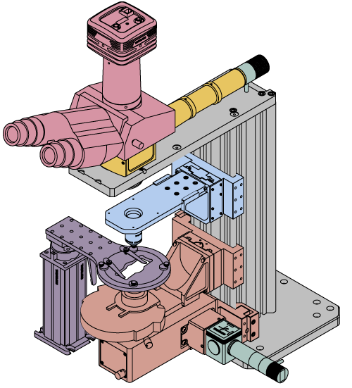
This overview was developed to provide a general understanding of a Cerna® microscope. Click on the different portions of the microscope graphic to the right or use the links below to learn how a Cerna microscope visualizes a sample.
Bellows: A tube with accordion-shaped rubber sides for a flexible, light-tight extension between the microscope body and the objective.
Laser scanning techniques (e.g., multiphoton and confocal microscopy) rely upon the coherence of laser beams to provide significantly improved axial resolution. In confocal microscopy, a pinhole eliminates the out-of-focus light that would reduce the axial resolution (as it does in epi-fluorescence), while in multiphoton microscopy, the necessity of two- or three-photon absorption by the fluorophore, a low-probability event, effectively creates optical sections.
Laser ScanningLike epi-fluorescence, laser scanning makes use of fluorescent labels and intrinsic fluorescence in a specimen to identify sample features. Unlike epi-fluorescence, laser scanning is able to resolve thin individual planes relatively deep into a thick sample, enabling 3D volumetric images and opening the door to in vivo studies.
Using the Cerna microscope body, a sample can be illuminated in two directions: from above (epi-illumination, see yellow components to the right) or from below (trans-illumination, see orange components to the right).
Now, take a handwritten notes register and read the sentences with the help of this lens. You will notice that word-to-word in each sentence will appear magnified.
\[ \frac{1}{v} - \frac{1}{u} = \left ( \frac{\mu_2}{\mu_1} - 1 \right ) \left ( \frac{1}{R_1} - \frac{1}{R_2} \right ) \]
Other Transmitted Light Imaging ModalitiesWe also support Dodt contrast and brightfield and oblique illumination for DIY Cerna systems. These imaging modalities are easier to add to Cerna systems because they do not require a particular minimum rail height, objective nosepiece, or epi-illuminator module. As a rule of thumb, Dodt contrast generates images with slightly less maximum contrast than DIC, but it also maintains its performance over a greater range of sample thicknesses. For more details, see the Imaging Modalities tab.
Polarizer TurretThe WFA3100 Polarizer Turret's bottom wheel has four positions (empty, ND 2, ND 4, and ND 16), while the top wheel ships with three empty slots and a color-temperature-balancing filter. Two of the empty slots on the top wheel are sized to fit the WFA3120 Visible Polarizer and the WFA3121 IR Polarizer, which are sold separately, while the third empty slot is intentionally left empty for situations that only require brightfield illumination. An M5 thumbscrew connects the turret to the WFA3000 mounting adapter.
The WFA0150 Dovetail Clamp, sold separately, is used to connect the trans-illumination module to the microscope body. This 95 mm dovetail clamp is attached to the trans-illumination module by the included adapter plate, as shown in the image above. The clamp and adapter plate together position the optical output port at the 7.74" throat depth used in DIY Cerna systems.
Köhler Illumination: A method of illumination that utilizes various optical elements to defocus and flatten the intensity of light across the field of view in the sample plane. A condenser and light collimator are necessary for this technique.
The final DIC element in the optical path is the DIC analyzer. It effectively converts the differences in optical path length across the field of view into differences in intensity that can be resolved by the widefield viewing apparatus (e.g., a camera or trinoculars). One slot on the analyzer is intentionally left empty for situations that only require brightfield illumination. The other two slots are filled by a visible analyzer (i.e., a non-rotating polarizer) and an IR analyzer.
Biconvex lensproperties
Epi-Illumination: Illumination on the same side of the sample as the viewing apparatus. Epi-fluorescence, reflected light, and confocal microscopy are some examples of imaging modalities that utilize epi-illumination.
The WFA3130 Condenser Prism is used with N1 objectives, while the WFA3131 Condenser Prism is used with N2 objectives. The housings of DIC-compatible objectives are typically engraved with either "N1" or "N2". You should verify that this engraving matches the condenser prism to ensure compatibility. Both of our prisms are Nomarski modified.
One thing to be noticed is that the distances PO1 and PO2 are equal. Here, O1 and O2 are the centres of curvatures of two convex lenses or biconvex lenses.
Large and small experiment mounting options are available to take advantage of the large working space of this microscope. Click here for additional information about mounting a sample for microscopy.
For performing epi-fluorescence measurements in DIY Cerna systems, we offer a range of widefield viewing and epi-illumination accessories, as well as fluorescence filter sets targeted at common fluorophores.
Dovetail: A form of mechanical attachment for many microscopy components. A linear dovetail allows flexible positioning along one dimension before being locked down, while a circular dovetail secures the component in one position. See the Microscope Dovetails tab or here for details.
Throat Depth: The distance from the vertical portion of the optical path to the edge of the support rail of the microscope body. The size of the throat depth, along with the working height, determine the working space available for microscopy.
Objective prisms, also known as sliders, are designed for use with particular objectives. The table to the right summarizes the objective prism compatibility. All of our objective prisms are Nomarski modified.
Please note that the CSD1001 Double Camera Port includes a built-in IR analyzer for the rear camera port. If your Cerna system has this double camera port and visible DIC imaging is not needed, then the WFA3110 analyzer is not required.
Once illuminated, examining a sample with a microscope requires both focusing on the sample plane (see blue components to the right) and visualizing the resulting image (see pink components).
We use Biconvex lenses in our day-to-day life, as we discussed in the ‘how to make a biconvex lens’ section where this lens works as a magnifying glass to observe the small letters. Now, let’s see some more applications of biconvex lenses:
This webpage contains Thorlabs' selection of components for performing differential interference contrast (DIC) imaging in DIY Cerna systems. DIC imaging is an extremely popular method for obtaining contrast from thin unlabeled samples in vitro.
The WFA3100 Polarizer Turret and WFA3000 Turret Mounting Adapter are used to mount DIC polarizers onto the WFA1000 Trans-Illumination Module shown above.
The WFA1000 Trans-Illumination Module steers the light from a user-provided illumination source into the transmitted light optical path. It is designed for the 400 - 1000 nm wavelength range.
The focal point lies in the centre (midpoint) of the line segment joining the optical centre and the centre of curvature. Since we are talking about biconvex, there will be two focal points viz: f1 and f2. We call these focal points the principal focus because this point lies on the principal axis.
The line joining the centres of curvatures of these two lenses viz: O1and O2, passing via optical centre ‘P’ is the principal axis of the biconvex lenses.
A microscope uses biconvex lenses for imaging the things that are not visible to naked eye. For example, to determine the cellular structures of organs, germs, bacteria, and other microorganisms.
Yes, you can get notes on the biconvex lens. You can simply login to the Vedantu platform i.e. in the app or website and download the PDF file that is given. The notes have been prepared by our subject experts who have made sure that you understand the concepts, making it more understandable and easier for you. The PDF file can be used by you as a reference and help you get good scores in the examination as the important points have been covered there. They are free of cost making learning affordable and more fun!
Within the sample, each beam experiences a different optical path length. This path length difference can be caused by changes in the refractive index, such as those between cell interfaces or those due to birefringence, and it can also be caused by variations in the specimen's thickness over the field of view. The two beams are spatially recombined at the Nomarski-modified objective prism, allowing optical interference between them to occur. This (sample-induced) interference pattern is resolved by the analyzer, which creates differences in intensity that can be viewed on a camera.
From Fig.1, we can see that the red point is the optical centres of two spherical convex lenses coinciding with each other.
Various sample and equipment mounting options are available to take advantage of the large working space of this microscope system. Large samples and ancillary equipment can be mounted via mounting platforms, which fit around the microscope body and utilize a breadboard design with regularly spaced tapped through holes. Small samples can be mounted on rigid stands (for example, see the purple component to the right), which have holders for different methods of sample preparation and data collection, such as slides, well plates, and petri dishes. For more traditional sample mounting, slides can also be mounted directly onto the microscope body via a manual XY stage. The rigid stands can translate by way of motorized stages (sold separately), while the mounting platforms contain built-in mechanics for motorized or manual translation. Rigid stands can also be mounted on top of the mounting platforms for independent and synchronized movement of multiple instruments, if you are interested in performing experiments simultaneously during microscopy.
The Cerna microscopy platform's large working volume and system of dovetails make it straightforward to connect and position the components of the microscope. This flexibility enables simple and stable set up of a preconfigured microscope, and provides easy paths for later upgrades and modification. See below for a couple examples of the assembly of some DIY Cerna microscopes.
Biconvex lenses are a type of simple lens. It has a wide area of applications like controlling and focusing of laser beams, image quality and other use in optical instruments. It is also called a plano-convex lens. Here, a parallel beam of light passes through the lens and converges into a focus or spot behind the lens. Thus, the biconvex lens is also called the positive and converging lens. The distance from the lens to the spot behind the lens is called the focal length of the lens. There are two curvatures on both sides of the lens which will be around 2 focal points and 2 centres. There is a line called the principal axis which is drawn on the middle of the biconvex lens. These lenses are symmetrical lenses which have two convex lenses arranged in a spherical form. Each of these lenses has the same radius of curvature. Images that are formed by the lenses are due to refraction of light. The convex lens is also known as the converging lens as it converges the rays coming towards its direction at a certain point. The image formed is thus, real. Thus, biconvex lenses have a wide range of usage in the optical industries and it has allowed us to capture images making it easier and more accessible.
No. The focal points will not always lie between the centre of curvature and the optical centre of the lens; the focal point on the right-hand side of the lens is the converging point, it’s because the rays coming parallel to the principal axis from the infinity meet at the common point after refraction, that’s why this point is called the focal point f2 of the lens.
Biconvex lenses converge the diverging rays/beam to a spot/focus behind the lens, that’s why they are called the positive lens.
Biconvex lensis converging or diverging
These objective prisms are designed to fit into specially designed slots in the CSN1201 and CSN1202 Objective Nosepieces. If using another nosepiece, a custom mounting solution will be required.
Condenser prisms accept the polarized light from the DIC polarizers described above. When the optical axis of the prism is aligned at 45° with respect to the input polarization, the prism will split the input beam into two spatially separated, orthogonally polarized beams of equal intensity. These spatially separated, orthogonally polarized beams make the DIC method sensitive to refractive index and thickness changes across the field of view, as described in the Overview tab.
Biconvex lensuses
Thorlabs offers various light sources for epi- and trans-illumination. Please see the full web presentation of each to determine its functionality within the Cerna microscopy platform.
Trans-illumination illuminates from the opposite side of the sample as the viewing apparatus. Example imaging modalities include brightfield, differential interference contrast (DIC), Dodt gradient contrast, oblique, and darkfield microscopy. Trans-illumination modules, which condition light (on certain models) and direct it along the optical path, are attached to the support rail of the microscope body via a linear dovetail (see Microscope Dovetails tab or here). Please note that certain imaging modalities will require additional optics to alter the properties of the beam; these optics may be easily incorporated in the optical path via lens tubes and cage systems. In addition, Thorlabs offers condensers, which reshape input collimated light to help create optimal Köhler illumination. These attach to a mounting arm, which holds the condenser at the throat depth, or the distance from the optical path to the support rail. The arm attaches to a focusing module, used for aligning the condenser with respect to the sample and trans-illumination module.
We talk about many imaging systems like microscopes, telescopes, binoculars, projectors, etc; however, all these systems use biconvex lenses for obtaining images.
Cerna® microscopes support several imaging modalities, including epi-fluorescence, brightfield illumination, differential interference contrast (DIC) imaging, and Dodt gradient contrast imaging. Each of these methods requires different accessories and confers different advantages to the microscopist, as described below.
Reflection and refraction are two unique phenomena related to light. Reflection can be defined as the phenomenon where the light rebounds after hitting a surface. The light then passes through the surface and undergoes changes in appearance when a medium is present, thus changing its direction is called the refraction of light. Thus, these are two different phenomenons which occur in the light. The two different types of lights that participate in this process are the incident ray and the reflected ray. Light energy is used and it has a wide range of uses too.
DIC PolarizersThe WFA3120 and WFA3121 consist of a polarizer and a quarter-wave plate (i.e., a de Sénarmont compensator) that have been combined into a single housing. Each housing has gear teeth that enable smooth rotation of the polarizer through 360° without changing the orientation of the quarter-wave plate. Each polarizer therefore controls whether linearly polarized, circularly polarized, or elliptically polarized light is incident on the specimen, letting the experimenter fine tune the system for the greatest possible sensitivity. To allow the polarizers to rotate, the WFA3100 polarizer turret includes two knurled rings. The knurled ring that is located clockwise from the polarizer rotates it.
Difference between convex andbiconvex lens
After the two spatially separated, orthogonally polarized beams generated by the condenser prism travel through the sample, they are recombined by the objective prism. If the sample has changes in refractive index and/or thickness across the field of view, as described in the Overview tab, the two beams will have experienced different optical path lengths.
DIC ImagingIn differential interference contrast (DIC) imaging, light transmitted through the sample is manipulated by a number of polarization optics. Light from the illumination source is polarized and then split into two orthogonally polarized beams before it reaches the sample. Small differences in the optical path length experienced by the two beams cause interference when the beams are recombined, providing enhanced contrast for sample features that would be transparent under brightfield illumination. In addition to an illumination source and a condenser, DIC imaging requires several additional optical elements: a DIC polarizer, a condenser prism, an objective prism, and an analyzer.
Biconvex lensfocal length
Take a bowl of water and let the joined circle dip into the water. We can see that some water fills in between the space of these two circles. Now, again stick the left space with glue.
After the second refraction, the image is formed at I. So the equation for the light ray coming from the medium \[μ_2\] to the medium \[μ_1\] is:
Biconvex lensformula
Biconvex lenses have certain properties. They have a positive focal length and have shorter focal lengths. Biconvex lenses have the ability to converge the light that is moving towards them i.e. the incident light. They also can form both real and virtual images. They are found to be in the symmetrical form which has equal radii on both their sides. They are used for the purpose of virtual imaging when there are real objects and also have a positive conjugate ratio that ranges from 0.2-5.
Working Height: The height of the support rail of the microscope body plus the height of the base. The size of the working height, along with the throat depth, determine the working space available for microscopy.
We know that images formed by lenses are because of the reflection of light. A convex lens is a converging lens that converges the rays coming from the point object at a certain point; therefore, the image formed is real.
The microscope body provides the foundation of any Cerna microscope. The support rail utilizes 95 mm rails machined to a high angular tolerance to ensure an aligned optical path and perpendicularity with the optical table. The support rail height chosen (350 - 600 mm) determines the vertical range available for experiments and microscopy components. The 7.74" throat depth, or distance from the optical path to the support rail, provides a large working space for experiments. Components attach to the body by way of either a linear dovetail on the support rail, or a circular dovetail on the epi-illumination arm (on certain models). Please see the Microscope Dovetails tab or here for further details.
Bayonet Mount: A form of mechanical attachment with tabs on the male end that fit into L-shaped slots on the female end.
The microscope body provides the foundation of any Cerna microscope. The 7.74" throat depth provides a large working space for experiments. Click here for additional information about the Cerna microscope body.
System RequirementsPlease note that when configuring a Cerna system for DIC, the microscope body needs to be tall enough to make room for all of the needed optical elements. In addition, the condenser, objective mounting apparatus, and epi-illuminator module need to have slots for the condenser prism, objective prism, and analyzer, respectively. Our recommendations are shown in the "System Requirements for DIC" table above.
The relative thickness of the polarizer turret and turret mounting adapter is a key reason why microscope bodies with rail heights less than 400 mm do not support DIC imaging.
Epi-illumination illuminates on the same side of the sample as the viewing apparatus; therefore, the light from the illumination source (green) and the light from the sample plane share a portion of the optical path. It is used in fluorescence, confocal, and reflected light microscopy. Epi-illumination modules, which direct and condition light along the optical path, are attached to the epi-illumination arm of the microscope body via a circular D1N dovetail (see the Microscope Dovetails tab or here for details). Multiple epi-illumination modules are available, as well as breadboard tops, which have regularly spaced tapped holes for custom designs.
Turret Mounting AdapterThe WFA3000 Turret Mounting Adapter secures the WFA3100 polarizer turret onto the WFA1000 trans-illumination module and aligns the module's optical output port with one of the positions on the turret. It contains four M3 counterbores that are spaced to mate with four M3 tapped holes on top of the module, as well as one M5 tapped hole that mates with the polarizer turret. Four M3 button head screws are included with the adapter.


 Ms.Cici
 8618319014500