
Theory and Practice of Optics & Refraction- E Book - optics and refraction
The set of intersections of the diffracted rays and the image plane forms a set of points, called a spot diagram. In Figure 8-1, several simple spot diagrams are shown; their horizontal axes are in the plane of dispersion (the tangential plane), and their vertical axes are in the sagittal plane. In (a) an uncorrected (out-of-focus) image is shown; (b) shows good tangential focusing, and (c) shows virtually point-like imaging. All three of these images are simplistic in that they ignore the effects of line curvature as well as higher-order aberrations (such as coma and spherical aberration), which render typical spot diagrams asymmetric, as in (d).
by F Vatansever · 2012 · Cited by 401 — A common type of specialized infrared heat lamp emits 2–25 μm radiation. IR saunas are often used and the most effective types have ceramic FIR emitting panels ...
Diffraction gratingexperiment
Yes, opt-in. By checking this box, you agree to receive our newsletters, announcements, surveys and marketing offers in accordance with our privacy policy
In Concave Diffraction Gratings, we formulated the optical imaging properties of a grating system in terms of wavefront aberrations. After arriving at a design, though, this approach is not ideal for observing the imaging properties of the system. Two tools of image analysis – spot diagrams and linespread functions – are discussed below.
A fundamental problem with geometric raytracing procedures (other than that they ignore the variations in energy density throughout a crosssection of the diffracted beam and the diffraction efficiency of the grating) is its ignorance of the effect that the size and shape of the exit aperture has on the measured resolution of the instrument.
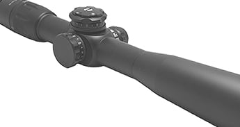
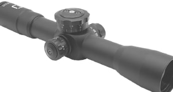
US Optics Riflescopes are custom built to exacting specifications ensuring sharp images, maximum clarity, and a rugged, punishment-proof housing. This engineered optical prescription gathers, filters, and transmits light from the objective lens to all inner optical elements to the eyepiece for a crystal clear image.

Diffraction gratingdiagram
Illinois Schools Products and Services. A K-12 school supply buyer's guide.
Parabolic mirrors are typically made as off-axis parabolic reflectors whose reflective surfaces are equivalent to a portion of the parent parabolic optical ...
Diffraction grating imagesphysics
polarized light, but when incident linearly polarized light is 45° to the quarter-wave plate, the one of the horizontal/vertical components of the polarized ...
For footnotes and additional insights into diffraction grating topics like this one, download our free MKS Diffraction Gratings Handbook (8th Edition)
Raytracing (using the laws of geometrical optics) is superior to wavefront aberration analysis in the determination of image quality. Aberration analysis is an approximation to image analysis, since it involves expanding quantities in infinite power series and considering only a few terms. Raytracing, on the other hand, does not involve approximations, but shows (in the absence of the diffractive effects of physical optics) where each ray of light incident on the grating will diffract. It would be more exact to design grating systems with a raytracing procedure as well, though to do so would be computationally cumbersome.
Here ƒ/noOUTPUT is the output focal ratio, r'(λ) is the focal distance for this wavelength, and W is the width of the grating. Results from raytrace analyses that use the laws of geometrical optics only should not be considered valid if the dimensions of the image are found to be near or below the diffraction limit calculated from Eq. (8-1).
Choose products to compare anywhere you see 'Add to Compare' or 'Compare' options displayed. Compare All Close
A straightforward method of evaluating the imaging properties of a spectrometer at a given wavelength is to measure the tangential and sagittal extent of an image (often called the width w' and height h' of the image, respectively).
There are 2 further types of OFAs; an EDFA (Erbium-Doped Fiber Amplifier) and an FRA (Fiber Raman Amplifier). Optical amplifiers, OFA (Optical Fiber Amplifier) ...
Diffraction grating imagesfree
This optical power meter is designed to measure irradiance and integrated power from a UV-LED light source.
Oct 2, 2020 — Ultrafast Laser Lab (PI: Prof. James Fraser) exploring nanophotonics and high-power laser solutions for advanced manufacturing (welding, ...
Geometric raytracing provides spot diagrams in good agreement with observed spectrometer images, except for well-focused images, in which the wave nature of light dictates a minimum size for the image. Even if the image of a point object is completely without aberrations, it is not a point image, due to the diffraction effects of the pupil (which is usually the perimeter of the grating). The minimal image size, called the diffraction limit, can be estimated for a given wavelength by the diameter a of the Airy disk for a mirror in the same geometry:
The treatment period is one hour. UV is emitted during the first 30 minutes, green light is emitted during the last 30 minutes, while red light is emitted ...
TRADESHOWS ; Safety Services Manitoba, Winnipeg, MB, Jan 21-23 ; NCMS Technology Showcase, Honolulu, HI, Jan 22-24 ; Industrial Safety Seminar, Saskatoon, SK, Feb ...
Type of Canon Camera Lens Mounts · 1. RF and RF-S · 2. EF, TS-E, MP-E · 3. EF-S · 4. EF-M.
The linespread calculation thus described accounts for the effect that the entrance and exit slit dimensions have on the resolution of the grating system.
An alternative to merely measuring the extent of a spectral image is to compute its linespread function, which is the convolution of the (monochromatic) image of the entrance slit with the exit aperture (the exit slit in a monochromator, or a detector element in a spectrograph). A close physical equivalent is obtained by scanning the monochromatic image by moving the exit aperture past it in the image plane and recording the light intensity passing through the slit as a function of position in this plane.
© 2024 EuroOptic. All rights reserved. | Sitemap | About Us | Terms & Conditions | NightforceUSA


 Ms.Cici
 8618319014500