
The Optical Shop - see.you optics
The laser's in-phase emission arises in other topics: it's the basis for transparency of materials. For example, whenever atoms in a glass window absorb light waves, they re-emit those waves in phase, so the original wave is preserved and the material acts transparent. In-phase emission prevents the light from scattering when it interacts with the atoms in the glass. So yes, the atoms in the laser-rod or laser gas-tube emit light in phase... making the laser material transparent, and this preserves whatever coherence that the incoming light might already have had. The "in phase" textbook laser diagram below is actually, heh, explaining transparency. Incoherent light could also get amplified and bounce as shown below. So, the authors never bothered to tell us how the light became coherent in the first place.
Care should be taken in choosing eyepiece/objective combinations to ensure the optimal magnification of specimen detail without adding unnecessary artifacts. For instance, to achieve a magnification of 250x, the microscopist could choose a 25x eyepiece coupled to a 10x objective. An alternative choice for the same magnification would be a 10x eyepiece with a 25x objective. Because the 25x objective has a higher numerical aperture (approximately 0.65) than does the 10x objective (approximately 0.25), and considering that numerical aperture values define an objective's resolution, it is clear that the latter choice would be the best. If photomicrographs of the same viewfield were made with each objective/eyepiece combination described above, it would be obvious that the 10x eyepiece/25x objective duo would produce photomicrographs that excelled in specimen detail and clarity when compared to the alternative combination.
OK, if spatially coherent light looks like an expanding bullseye, then what does INCOHERENT light look like? In the above diagram 2A, incoherence instead would look like multiple pinholes and bunches of overlapped bullseyes. Lots of interference patterns, and probably with the nodes dynamically swerving around. Either that or it would look like fig. 2b but with bunches of light rays from multiple pinholes, and the rays all cross each other throughout the light beam. In both cases if the incorherent light was focused by a lens, we wouldn't produce any infinitely tiny hot spot. Can't punch holes in razor blades.
Instead I'm following the usual distinction made by the intro textbooks. In these books, perfectly coherent light is explained separately from perfectly monochromatic light (i.e., spatial coherence is not temporal coherence.) Here I'm ignoring single-frequency waves, and only explaining the ideal pinhole-light, white light from wavelength-size apertures. Also, I'm not treating light from extended apertures. I'm explaining the light from distant stars, not the light from nearby Betelgeuse.
Whenever atoms in a laser are emitting EM waves in phase with incoming EM waves, the emitted waves add to the incoming light, making it brighter. Two plus two equals four. But amplification doesn't create any "in phase light." If two plus two is four, the resulting 4 is purely a number, and it isn't concealing any 2 + 2. Instead it could be one plus three, or nine minus five. I mean, when two in-phase waves add together to create an amplified wave, the original waves are gone. The larger wave doesn't forever travel along as two smaller "inphase waves" in the way all those intro laser explanations depict. Instead, all those diagrams should show that smaller waves add together to create single, larger waves. Amplification. Not some sort of "coherence-izing effect."
Oct 22, 2024 — Laser - Light, Amplification, Coherence: Laser emission is shaped by the rules of quantum mechanics, which limit atoms and molecules to ...
There are two major types of eyepieces that are grouped according to lens and diaphragm arrangement: the negative eyepieces with an internal diaphragm and positive eyepieces that have a diaphragm below the lenses of the eyepiece. Negative eyepieces have two lenses: the upper lens, which is closest to the observer's eye, is called the eye-lens and the lower lens (beneath the diaphragm) is often termed the field lens. In their simplest form, both lenses are plano-convex, with convex sides "facing" the specimen. Approximately mid-way between these lenses there is a fixed circular opening or internal diaphragm which, by its size, defines the circular field of view that is observed in looking into the microscope.
Also, this article is aimed at the general public as well as grade-school teachers and students. So, no math whatsoever! Also, this article explains IDEAL coherence: light with perfect spatial coherence.
If we could see light and radio waves, could we find any little sinewave-snakes anywhere? Nope. Take a look at the second video above right. It shows what EM waves would actually look like, if we could see them. It's an animation of flux lines surrounding a very tiny light source. The EM waves expand like layers of an onion. The flux lines break loose from the source, close upon themselves to form loops, then fly off into space. Of course if we graphed the field strengths on a voltage axis, they would form sine waves, as shown in the first video. But the flux itself isn't like a snake. It points entirely sideways all the time, like closed rings with no sine wiggles. And of course there isn't any "Aether medium" which could wiggle like transverse sine waves. No little snakes flying through space. Like atoms being little solar systems, the wiggles were "lies to children." Or, they were simply wrong.
Fig. 3 SOMEONE GETS IT RIGHT! The above unattributed diagram found in online archives. In the distant past, monochromatic coherent sources were also microwatt light sources, no getting around it. Creating coherent light meant throwing away almost all of the power. Sending many milliwatts of light through a wavelength-diameter pinhole was basically impossible. So, all the bizarre and wonderful capabilities of lasers were unreachable. But lasers easily solved the problem because, right at the start, they create some spherewave "pinhole light," as if their entire light output came from a single virtual pinhole; a pinhole which is less than 500nM across. Aha, those confocal/concentric resonator mirrors, the ones used in lasers? This means that the "virtual pinhole" in an actual laser is just a non-virtual, very real pinhole-image sitting in the space between the mirrors. (See wikipedia diagrams for optical cavities, http://en.wikipedia.org/wiki/Optical_cavity). And all of those Semiconductor Lasers with parallel mirrors: they just employ an "infinite mirror tunnel" in order to place their pointsource at virtual-infinity distance, where it behaves just like the light from a distant star. During its trip down the infinite tunnel, all the non-planewave light wanders out the sides of the tunnel. Only planewave light can persist in the tunnel and get amplified. So ...laser coherence is created by the mirror-tunnel. Not by transparency or stimulated emission or 'stacked sinewaves." Or in proper terms, coherence is created by the laser's Fabry-Perot resonator cavity, and not by any sideways packing of long narrow string-like "photons." And all the above means that we now have a simple, gut-level intuitive picture of laser coherence. What is it? Coherent laser light is just pinhole-light produced by an infinite mirror-tunnel, with amplification. Sort of like those disco-era mirror-infinity toys from Spencer Gifts. But the depths of their virtual tunnel wouldn't be dark. On each reflection, the light passes through the laser-medium and gets slightly brighter. And on each pass, the "virtual source" seems farther away inside the tunnel. Viewed from the end, each deeper segment of the "tunnel" appears slightly brighter and smaller ...and the far end of the tunnel looks like an infinitely bright, infinitely tiny star. If you stare into the depths of the Amplifying Disco Infinity Mirror, the "star" is small and bright enough to punch a hole right through your retina. And it doesn't even have to be very bright to do this! A hundred-watt incandescent light bulb doesn't slice up your retina, but a quarter-watt laser can burn a tattoo permanently into the back of your eye. "Coherent" can also mean "sharp when focused," since focused Coherent light must all converge to an infinitely small point. (Yeah yeah diffraction limit. We're talking simple idealized geometrical optics here.) OK, if spatially coherent light looks like an expanding bullseye, then what does INCOHERENT light look like? In the above diagram 2A, incoherence instead would look like multiple pinholes and bunches of overlapped bullseyes. Lots of interference patterns, and probably with the nodes dynamically swerving around. Either that or it would look like fig. 2b but with bunches of light rays from multiple pinholes, and the rays all cross each other throughout the light beam. In both cases if the incorherent light was focused by a lens, we wouldn't produce any infinitely tiny hot spot. Can't punch holes in razor blades. With our gut-level intuitive understanding of Laser Coherence, we can now construct a basic list of coherent light sources Sources in increasing coherence Bright cloudy sky (least spatially coherent) Fluorescent tube lamp Frosted incandescent bulb Sun during clear weather Clear incandescent bulb Clear incandescent bulb w/noncoil filament (aquarium bulb) LED Electric welding arc 50ft away Laser (coherence-leng in MMs, up to a few Meters) Starlight (coherence leng 1000s KM) Note that the list also is a list of DEcreasing visible source-width, with the cloudy sky at the top and the distant stars at the bottom. As a little kid, did you believe that the light from clear incandescent bulbs was more magical than the frosted ones? And the light of garage welders was even more magical still? If so, you were intuitively experiencing optical coherence. Your little brain was wanting to mess around with laser sources, rather than overcast daylight. A perfect ideal pointsource gives perfectly coherent light, while a wide diffuse source gives the least coherent light. Turn the idea backwards: if we start out with perfectly coherent laser light, but then we send it through a frosted screen, the light remains just as monochromatic, but it becomes incoherent. Hey, I noticed that we can actually buy an incoherent-izer, an opto device for our optical bench. They're just a rotating frosted screen with a little motor (since an unmoving frosted screen still leaves a small bit of micro-scale coherence or "laser speckle.") NO JPEG YET Fig. 4 A frosted screen makes light incoherent. REAL SOLAR DEATH-RAY And now I have the answer to a big question that plagued me in childhood. No doubt all the nasty little science-boys like me had come up with this one. Why can't I make a death ray light-source? I could just get my big plastic fresnel lens and focus sunlight, and then somehow collimate it into a half-mm beam. The 0.50mm burning spot would appear anywhere along the parallel beam miles long. Write CHAIRFACE on the freakin' moon! But if we think about this now, it turns out to be impossible. Adding extra lenses to our solar furnace just creates a projector, where our parallel solar deathray spreads out and becomes a wide image of the sun. The darned sun isn't a pointsource. No thin beam is possible unless we include a tenth-micron pinhole in the optical path, and that turns the power into microwatts. The solution to the problem is simple: JUST REPLACE THE SUN WITH A 10KM WHITE DWARF STAR HA HAAAA! Keep the sun's brightness the same, but shrink the sun until it appears in the sky like a tiny star, like an extremely intense pinpoint. Now just use any big lens to gather a square meter of sunlight, focus it down to 1mm, then collimate it with a 1mm water-cooled short-focus quartz lens stolen from an ultraviolet microscope. Yes, the whole device is still a projector, but if we project the image of a pointsource into the distance, the result is an intense collimated beam. Other than a bit of diffraction it should work great: a few hundred watts in a parallel CW beam 1mm wide. Slice-a offs you fingas! Winston Kock, one of the early laser people at Bell Labs, said that laser light is "sharper light" which can be used as a cutting tool. Exactly, exactly! Winston Kock actually gets it. But the actual central concept is that coherence or "pinhole light" is the whole reason for the "sharp light" which does the laser-cutting. Lasers aren't particularly bright. Hundred watt light bulbs? 5,000 watt spotlights for school play?? Or daytime sunlight? If our sun was 10KM wide, or reduced to 10^5 times smaller in visual angle, then its light would be spatially coherent like lasers, or like an electric welding arc, and glancing upwards during the day might slice grooves across our retinas. The lens of your eye will focus the white-dwarf sunlight to a pinpoint rather than to a dim and safe little 0.3deg solar disk on your retina. Only because sunlight is non-parallel, because our sun is an extended source, our 1.5 KWatt/m^2 sunlight doesn't act like dangerous laser light. Hmmm, hold on a sec. If sunlight is about 1500 watts per square meter, and your eye's pupil is about 1mm, then your pupil intercepts 1500W/.001^2 = 1.5mW. DOH! WRONG! OK, staring at white-dwarf sunlight would actually be just like staring into a cheap laser pointer. Those things don't become really dangerous to human eyes until up around 5mW. AHA, but using binoculars would be bad, very bad: 5000X smaller exit aperture, creating an eight watt parallel beam 1mm in diameter. Binoculars become like icepicks aimed at your eyeballs. Coherent light can be nasty.
Simple eyepieces such as the Huygenian and Ramsden and their achromatized counterparts will not correct for residual chromatic difference of magnification in the intermediate image, especially when used in combination with high magnification achromatic objectives as well as any fluorite or apochromatic objectives. To remedy this, manufacturers produce compensating eyepieces that introduce an equal, but opposite, chromatic error in the lens elements. Compensating eyepieces may be either of the positive or negative type, and must be used at all magnifications with fluorite, apochromatic and all variations of plan objectives (they can also be used to advantage with achromatic objectives of 40x and higher). In recent years, modern microscope objectives have their correction for chromatic difference of magnification either built into the objectives themselves (Olympus and Nikon) or corrected in the tube lens (Leica and Zeiss).
Eyepieces work in combination with microscope objectives to further magnify the intermediate image so that specimen details can be observed. Oculars is an alternative name for eyepieces that has been widely used in the literature, but to maintain consistency during this discussion we will refer to all oculars as eyepieces.
Stagemicroscopefunction
For highly accurate measurements a Filar Micrometer similar to the one illustrated in Figure 6 is used. This micrometer replaces the conventional eyepiece and contains several improvements over conventional reticles. In the filar micrometer, a reticle with a measuring scale (there are many variations in scale types) and a very fine wire is brought into focus with the specimen (Figure 6(b)). The wire is mounted so that it can be slowly moved across the viewfield by the calibrated thumbscrew located on the side of the micrometer (Figure 6(a)). One complete turn of the thumbscrew (divided into 100 equal divisions) equals the distance between two adjacent reticle marks. By slowly moving the wire from one position on the specimen image to another and taking note of the changes in thumb screw numbers, the microscopist has a much more accurate measurement of distance. Filar micrometers (and other simple reticles) must be calibrated with a stage micrometer for each objective with which it will be used.
Whatiseyepieceinmicroscope
Some eyepieces have a movable "pointer" located within the eyepiece and positioned so that it appears as a silhouette in the image plane. This pointer is useful when indicating certain features of a specimen, especially when a microscopist is teaching students about specific features. Most eyepiece pointers can be rotated in a 360 degree angle around the specimen and more advanced versions can translate across the viewfield.
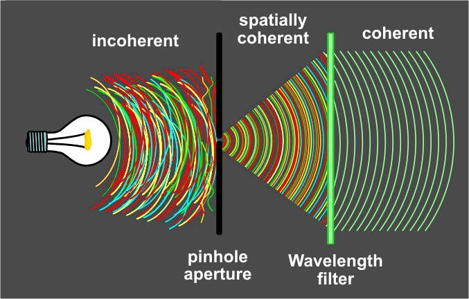
And finally I know why lasers are so wonderful: lasers are pinhole light sources which are ...actually bright! It's always been easy to make some coherent light, just use a normal light source and an optically small pinhole (a halfwave diameter.) A frosted light bulb can become a coherent light source. But a pinhole aperture this small will block nearly all the light from any conventional source. To experiment with this, get a slide projector and make a slide with a pinhole: an Al foil layer perforated by a needle. Add a narrowband green filter, and that's your Gabor-approved 1940s laser source. Make some holograms? Heh, a bit long exposure-time though.
As a kid I was always confused by explanations of coherent light. I'd been told that coherence had something to do with the sinusoidal shape of photons. Light is supposedly made up of little wiggling string-shapes; transverse waves. Textbooks show each photon as a kind of little "snake" moving side to side. And, supposedly, whenever all the "snakes" pack together side by side with their wiggles aligned, that's Coherence. Atoms in a laser are all emitting their light in phase-lock, and supposedly the end result is a special kind of "Inphase Light," where the little sine-waves stack up together, much like egg cartons.
In the distant past, monochromatic coherent sources were also microwatt light sources, no getting around it. Creating coherent light meant throwing away almost all of the power. Sending many milliwatts of light through a wavelength-diameter pinhole was basically impossible. So, all the bizarre and wonderful capabilities of lasers were unreachable. But lasers easily solved the problem because, right at the start, they create some spherewave "pinhole light," as if their entire light output came from a single virtual pinhole; a pinhole which is less than 500nM across. Aha, those confocal/concentric resonator mirrors, the ones used in lasers? This means that the "virtual pinhole" in an actual laser is just a non-virtual, very real pinhole-image sitting in the space between the mirrors. (See wikipedia diagrams for optical cavities, http://en.wikipedia.org/wiki/Optical_cavity). And all of those Semiconductor Lasers with parallel mirrors: they just employ an "infinite mirror tunnel" in order to place their pointsource at virtual-infinity distance, where it behaves just like the light from a distant star. During its trip down the infinite tunnel, all the non-planewave light wanders out the sides of the tunnel. Only planewave light can persist in the tunnel and get amplified. So ...laser coherence is created by the mirror-tunnel. Not by transparency or stimulated emission or 'stacked sinewaves." Or in proper terms, coherence is created by the laser's Fabry-Perot resonator cavity, and not by any sideways packing of long narrow string-like "photons." And all the above means that we now have a simple, gut-level intuitive picture of laser coherence. What is it? Coherent laser light is just pinhole-light produced by an infinite mirror-tunnel, with amplification. Sort of like those disco-era mirror-infinity toys from Spencer Gifts. But the depths of their virtual tunnel wouldn't be dark. On each reflection, the light passes through the laser-medium and gets slightly brighter. And on each pass, the "virtual source" seems farther away inside the tunnel. Viewed from the end, each deeper segment of the "tunnel" appears slightly brighter and smaller ...and the far end of the tunnel looks like an infinitely bright, infinitely tiny star. If you stare into the depths of the Amplifying Disco Infinity Mirror, the "star" is small and bright enough to punch a hole right through your retina. And it doesn't even have to be very bright to do this! A hundred-watt incandescent light bulb doesn't slice up your retina, but a quarter-watt laser can burn a tattoo permanently into the back of your eye. "Coherent" can also mean "sharp when focused," since focused Coherent light must all converge to an infinitely small point. (Yeah yeah diffraction limit. We're talking simple idealized geometrical optics here.) OK, if spatially coherent light looks like an expanding bullseye, then what does INCOHERENT light look like? In the above diagram 2A, incoherence instead would look like multiple pinholes and bunches of overlapped bullseyes. Lots of interference patterns, and probably with the nodes dynamically swerving around. Either that or it would look like fig. 2b but with bunches of light rays from multiple pinholes, and the rays all cross each other throughout the light beam. In both cases if the incorherent light was focused by a lens, we wouldn't produce any infinitely tiny hot spot. Can't punch holes in razor blades. With our gut-level intuitive understanding of Laser Coherence, we can now construct a basic list of coherent light sources Sources in increasing coherence Bright cloudy sky (least spatially coherent) Fluorescent tube lamp Frosted incandescent bulb Sun during clear weather Clear incandescent bulb Clear incandescent bulb w/noncoil filament (aquarium bulb) LED Electric welding arc 50ft away Laser (coherence-leng in MMs, up to a few Meters) Starlight (coherence leng 1000s KM) Note that the list also is a list of DEcreasing visible source-width, with the cloudy sky at the top and the distant stars at the bottom. As a little kid, did you believe that the light from clear incandescent bulbs was more magical than the frosted ones? And the light of garage welders was even more magical still? If so, you were intuitively experiencing optical coherence. Your little brain was wanting to mess around with laser sources, rather than overcast daylight. A perfect ideal pointsource gives perfectly coherent light, while a wide diffuse source gives the least coherent light. Turn the idea backwards: if we start out with perfectly coherent laser light, but then we send it through a frosted screen, the light remains just as monochromatic, but it becomes incoherent. Hey, I noticed that we can actually buy an incoherent-izer, an opto device for our optical bench. They're just a rotating frosted screen with a little motor (since an unmoving frosted screen still leaves a small bit of micro-scale coherence or "laser speckle.") NO JPEG YET Fig. 4 A frosted screen makes light incoherent. REAL SOLAR DEATH-RAY And now I have the answer to a big question that plagued me in childhood. No doubt all the nasty little science-boys like me had come up with this one. Why can't I make a death ray light-source? I could just get my big plastic fresnel lens and focus sunlight, and then somehow collimate it into a half-mm beam. The 0.50mm burning spot would appear anywhere along the parallel beam miles long. Write CHAIRFACE on the freakin' moon! But if we think about this now, it turns out to be impossible. Adding extra lenses to our solar furnace just creates a projector, where our parallel solar deathray spreads out and becomes a wide image of the sun. The darned sun isn't a pointsource. No thin beam is possible unless we include a tenth-micron pinhole in the optical path, and that turns the power into microwatts. The solution to the problem is simple: JUST REPLACE THE SUN WITH A 10KM WHITE DWARF STAR HA HAAAA! Keep the sun's brightness the same, but shrink the sun until it appears in the sky like a tiny star, like an extremely intense pinpoint. Now just use any big lens to gather a square meter of sunlight, focus it down to 1mm, then collimate it with a 1mm water-cooled short-focus quartz lens stolen from an ultraviolet microscope. Yes, the whole device is still a projector, but if we project the image of a pointsource into the distance, the result is an intense collimated beam. Other than a bit of diffraction it should work great: a few hundred watts in a parallel CW beam 1mm wide. Slice-a offs you fingas! Winston Kock, one of the early laser people at Bell Labs, said that laser light is "sharper light" which can be used as a cutting tool. Exactly, exactly! Winston Kock actually gets it. But the actual central concept is that coherence or "pinhole light" is the whole reason for the "sharp light" which does the laser-cutting. Lasers aren't particularly bright. Hundred watt light bulbs? 5,000 watt spotlights for school play?? Or daytime sunlight? If our sun was 10KM wide, or reduced to 10^5 times smaller in visual angle, then its light would be spatially coherent like lasers, or like an electric welding arc, and glancing upwards during the day might slice grooves across our retinas. The lens of your eye will focus the white-dwarf sunlight to a pinpoint rather than to a dim and safe little 0.3deg solar disk on your retina. Only because sunlight is non-parallel, because our sun is an extended source, our 1.5 KWatt/m^2 sunlight doesn't act like dangerous laser light. Hmmm, hold on a sec. If sunlight is about 1500 watts per square meter, and your eye's pupil is about 1mm, then your pupil intercepts 1500W/.001^2 = 1.5mW. DOH! WRONG! OK, staring at white-dwarf sunlight would actually be just like staring into a cheap laser pointer. Those things don't become really dangerous to human eyes until up around 5mW. AHA, but using binoculars would be bad, very bad: 5000X smaller exit aperture, creating an eight watt parallel beam 1mm in diameter. Binoculars become like icepicks aimed at your eyeballs. Coherent light can be nasty.
And photons? ...the photons are either dimensionless particles, or they're broad wavefunctions which are 'quantized.' They're either like infinitely small bullets flying in straight lines, or they're like enormous expanding EM pond-ripples from a thrown pebble. Photons aren't shaped like twisty snakes, they're nothing like a transverse wave on a string.

Microscopeparts and functions
Features · Round Mirror Diameters: 7.0 mm, 1/2", 19.0 mm, 1", 2", 3", or 4" · Square Mirror Edge Lengths: 1/2", 1", or 2" · Four Broadband Coating Options.
ADDENDUM: General mathematical theory of EM partial coherence If you read the first paragraphs here, you'd know that this article only describes Spatial Coherence, not temporal coherence or monochromatic light. (Important! Don't miss it.) Also, this article is aimed at the general public as well as grade-school teachers and students. So, no math whatsoever! Also, this article explains IDEAL coherence: light with perfect spatial coherence. On the other hand, Partial spatial coherence is a whole 'nother kettle of fish, and is nearly impenetrable without recourse to algebra and trig. Even further: the mathematical "coherence" concept in general; the mixture of spatial and temporal coherence ...is not mentioned anywhere here. Instead I'm following the usual distinction made by the intro textbooks. In these books, perfectly coherent light is explained separately from perfectly monochromatic light (i.e., spatial coherence is not temporal coherence.) Here I'm ignoring single-frequency waves, and only explaining the ideal pinhole-light, white light from wavelength-size apertures. Also, I'm not treating light from extended apertures. I'm explaining the light from distant stars, not the light from nearby Betelgeuse. In other words, where kids and the public are concerned, the term "coherent light" has a distinct meaning. It does not mean generalized coherence. Instead, for the greater public, "coherent light" means "light of perfect spatial-coherence," such as white light from ideal pinholes. But at the university level things are very different, where the term "Coherence" means a general theory; a mathematical description of non-ideal partial coherence which combines monochromatic light with the light from non-pinhole extended sources. A general theory of coherence does not divide temporal coherence from spatial. Do "textbooks" get Coherence completely wrong? Yes: grade-school textbooks, K-12 textbooks. Also articles written for public consumption, they get it wrong too. But the college textbooks, they're fine. They go into the rigorous details of partial coherence, and mixtures of spatial and temporal coherence, and they don't teach us that photons are like little sine-waves which can pack together like cardboard egg-cartons. SEE ALSO: Optics 421: Space & temp coherence Van-Cittert/Zernike theorem Etendue Common Laser Misconceptions Laser light is not "in-phase" light Laser light is not parallel light In-phase emission does not lead to coherent light Electricity misconceptions Essay collection List of misconceptions Electricity F.A.Q. http://amasci.com/miscon/coherenc.html Created and maintained by Bill Beaty. Mail me at: . View My Stats
A modified version of the Ramsden eyepiece is known as the Kellner eyepiece, as illustrated on the left in Figure 3. These improved eyepieces contain a doublet of eye-lens elements cemented together and feature a higher eye point than either the Ramsden or Huygenian eyepiece as well as a much larger field of view. A modified version of the simple Huygenian eyepiece is also illustrated in Figure 3, on the right. While these modified eyepieces perform better than their simple one-lens counterparts, they are still only useful with low-power achromat objectives.
The other main kind of eyepiece is the positive eyepiece with a diaphragm below its lenses, commonly known as the Ramsden eyepiece, as illustrated in Figure 2 (on the left). This eyepiece has an eye lens and field lens that are also plano-convex, but the field lens is mounted with the curved surface facing towards the eye lens. The front focal plane of this eyepiece lies just below the field lens, at the level of the eyepiece diaphragm, making this eyepiece readily adaptable for mounting reticles. To provide better correction, the two lenses of the Ramsden eyepiece may be cemented together.
So where is the equivalent power in the concept of "coherence?" How do I use those stacked-snakes to explain many other things? Where do the parallel wiggles clarify a radio antenna, a loudspeaker, or water waves? And if my laser isn't coherent enough to make holograms, can I draw a very simple picture of the problem's exact nature? A simple picture that any kid could understand? No. It just didn't connect.
More advanced eyepiece designs resulted in the Periplan eyepiece that is illustrated in Figure 4 above. This eyepiece contains seven lens elements that are cemented into a single doublet, a single triplet, and two individual lenses. Design improvements in periplan eyepieces lead to better correction for residual lateral chromatic aberration, increased flatness of field, and a general overall better performance when used with higher power objectives.
ADDENDUM: General mathematical theory of EM partial coherence If you read the first paragraphs here, you'd know that this article only describes Spatial Coherence, not temporal coherence or monochromatic light. (Important! Don't miss it.) Also, this article is aimed at the general public as well as grade-school teachers and students. So, no math whatsoever! Also, this article explains IDEAL coherence: light with perfect spatial coherence. On the other hand, Partial spatial coherence is a whole 'nother kettle of fish, and is nearly impenetrable without recourse to algebra and trig. Even further: the mathematical "coherence" concept in general; the mixture of spatial and temporal coherence ...is not mentioned anywhere here. Instead I'm following the usual distinction made by the intro textbooks. In these books, perfectly coherent light is explained separately from perfectly monochromatic light (i.e., spatial coherence is not temporal coherence.) Here I'm ignoring single-frequency waves, and only explaining the ideal pinhole-light, white light from wavelength-size apertures. Also, I'm not treating light from extended apertures. I'm explaining the light from distant stars, not the light from nearby Betelgeuse. In other words, where kids and the public are concerned, the term "coherent light" has a distinct meaning. It does not mean generalized coherence. Instead, for the greater public, "coherent light" means "light of perfect spatial-coherence," such as white light from ideal pinholes. But at the university level things are very different, where the term "Coherence" means a general theory; a mathematical description of non-ideal partial coherence which combines monochromatic light with the light from non-pinhole extended sources. A general theory of coherence does not divide temporal coherence from spatial. Do "textbooks" get Coherence completely wrong? Yes: grade-school textbooks, K-12 textbooks. Also articles written for public consumption, they get it wrong too. But the college textbooks, they're fine. They go into the rigorous details of partial coherence, and mixtures of spatial and temporal coherence, and they don't teach us that photons are like little sine-waves which can pack together like cardboard egg-cartons. SEE ALSO: Optics 421: Space & temp coherence Van-Cittert/Zernike theorem Etendue Common Laser Misconceptions Laser light is not "in-phase" light Laser light is not parallel light In-phase emission does not lead to coherent light Electricity misconceptions Essay collection List of misconceptions Electricity F.A.Q. http://amasci.com/miscon/coherenc.html Created and maintained by Bill Beaty. Mail me at: . View My Stats
Body tubemicroscopefunction
Light rays emanating from the eyepiece intersect at the exit pupil or eye point, often referred to as the Ramsden disc, where the pupil of the microscopists eye should be placed in order for her to see the entire field of view (usually 8-10 mm from the eye lens). By increasing the magnification of the eyepiece, the eye point is drawn closer to the upper surface of the eye lens, making it much more difficult for the microscopist to use, especially if they are wearing eyeglasses. To compensate for this, specially designed high eye point eyepieces have been manufactured that feature eye point distances approaching 20-25 mm above the surface of the eye lens. These improved eyepieces have larger diameter eye lenses that contain more optical elements and usually feature improved flatness of field. Such eyepieces are often designated with the inscription "H" somewhere on the eyepiece housing, either alone or in combination with other abbreviations, as discussed above. We should mention that high eye point eyepieces are especially useful for microscopists who wear eyeglasses to correct for near or far sightedness, but they do not correct for several other visual defects, such as astigmatism. Today, high eye point eyepieces are very popular, even with people who do not wear eyeglasses, because the large eye clearance reduces fatigue and makes viewing images through the microscope much more pleasurable.
High power objectivemicroscopefunction
Modern microscopes feature vastly improved plan-corrected objectives in which the primary image has much less curvature of field than older objectives. In addition, most microscopes now feature much wider body tubes that have greatly increased the size of intermediate images. To address these new features, manufacturers now produce wide-eyefield eyepieces (illustrated in Figure 1) that increase the viewable area of the specimen by as much as 40 percent. Because the strategies of eyepiece-objective correction techniques vary from manufacturer to manufacturer, it is very important (as stated above) to use only eyepieces recommended by a specific manufacturer for use with their objectives.
If fig. 1 above is wrong, then what's right? If we could actually see individual light waves, what would coherent light look like? Fortunately the explanation is quite simple. Take a look at figure 2A below. That's what perfectly coherent light would look like if we could see the waves. Coherent light is simple: it's light which comes from a very small light source. Light from a single source is always coherent, since incoherence requires two sources. Spatially coherent light has another name: "sphere waves" or "plane waves." Or even simpler: "pinhole light" or "pointsource light."
REAL SOLAR DEATH-RAY And now I have the answer to a big question that plagued me in childhood. No doubt all the nasty little science-boys like me had come up with this one. Why can't I make a death ray light-source? I could just get my big plastic fresnel lens and focus sunlight, and then somehow collimate it into a half-mm beam. The 0.50mm burning spot would appear anywhere along the parallel beam miles long. Write CHAIRFACE on the freakin' moon! But if we think about this now, it turns out to be impossible. Adding extra lenses to our solar furnace just creates a projector, where our parallel solar deathray spreads out and becomes a wide image of the sun. The darned sun isn't a pointsource. No thin beam is possible unless we include a tenth-micron pinhole in the optical path, and that turns the power into microwatts. The solution to the problem is simple: JUST REPLACE THE SUN WITH A 10KM WHITE DWARF STAR HA HAAAA! Keep the sun's brightness the same, but shrink the sun until it appears in the sky like a tiny star, like an extremely intense pinpoint. Now just use any big lens to gather a square meter of sunlight, focus it down to 1mm, then collimate it with a 1mm water-cooled short-focus quartz lens stolen from an ultraviolet microscope. Yes, the whole device is still a projector, but if we project the image of a pointsource into the distance, the result is an intense collimated beam. Other than a bit of diffraction it should work great: a few hundred watts in a parallel CW beam 1mm wide. Slice-a offs you fingas!
To get right down to it, light isn't a transverse wave. Or more specifically, light isn't a "transverse wave in the Aether," instead light is a wave in magnetic and electric fields where the field vectors point sideways. But the flux lines themselves don't wiggle sideways, and the flux doesn't contain any sine-wave shapes. Take a look at the video below left. The animated graph depicts the field strengths found along a single straight line: the values of the fields when a light wave is passing towards the right. The only sinewaves present are found in the pattern of intensity, in the sine-graph of field strength measurements. That sine wave is not a flux shape in space. In that vid, the only space involved is a straight-line axis with no wiggles.
But somehow this explanation just wouldn't stick to my brain. It didn't fit with everything else I knew. And worse still, I couldn't use the explanation as a tool. On one hand, the typical explanation of monochromatic laser light was very useful in many situations. Pure color means single frequency, and that implies narrow peaks in the spectrum graphs, and tiny spots on the radio dial. "Monochromatic light" connects with audio, where the pure tones such as flute-notes are monochromatic, while an impure broad-spectrum tone sounds like pink noise (or perhaps violins.) And in holography, whenever the frequency of light is moved high or low, I could imagine how this would slide all those tiny diffraction patterns around on my film. That would blur the patterns and make holography impossible, so clearly a hologram camera needs a very monochromatic light source. As a concept, "Monochromatic" works!
diffraction limit. diffraction limit. The diffraction limit is the resolution limit due to diffraction of an electron wave for the optical system with no ...
Manufacturers often produce specialized eyepieces, often termed photo eyepieces, that are designed to be used with photomicrography. These eyepieces are usually negative (Huygenian type) and are not capable of being used visually. For this reason, they are typically called projection lenses. A typical projection lens is illustrated in Figure 7 below.
So coherent light is just "pointsource light?" Paraphrasing Feynman: Now I Understand Evvvvvrrreeethiiing! Finally it all makes perfect sense: starlight is ULTIMATELY coherent, that's why Stellar Interferometry works. Starlight has coherence-lengths in thousands of KM, starlight is far more coherent than any human-made laser light. And the most distant stars are just like ideal point sources. I remember AA Michelson discovering that Betlegeuse is far less coherent than other stars. Ha, far less like a microscopic pointsource! Then I suddenly remember Dennis Gabor, inventing holography before lasers existed. To create his pseudo-lasers he just took light from an ordinary mercury-arc lamp and passed it through a pinhole. Mercury's emission line made it nearly monochromatic, and the pinhole gave it the spatial coherence.
On the other hand, Partial spatial coherence is a whole 'nother kettle of fish, and is nearly impenetrable without recourse to algebra and trig. Even further: the mathematical "coherence" concept in general; the mixture of spatial and temporal coherence ...is not mentioned anywhere here.
At one time, eyepieces were available in a wide spectrum of magnifications ranging from 6.3x to 25x and sometimes even higher for special applications. These eyepieces are very useful for observation and photomicrography with low-power objectives. Unfortunately, with higher power objectives, the problem of empty magnification becomes important when using very high magnification eyepieces and these should be avoided. Today most manufacturers restrict their eyepiece offerings to those in the 10x to 20x range. The diameter of the viewfield in an eyepiece is expressed as a "field-of-view number" or field number (FN), as discussed above. Information about the field number of an eyepiece can yield the real diameter of the object viewfield using the formula:
A perfect ideal pointsource gives perfectly coherent light, while a wide diffuse source gives the least coherent light. Turn the idea backwards: if we start out with perfectly coherent laser light, but then we send it through a frosted screen, the light remains just as monochromatic, but it becomes incoherent. Hey, I noticed that we can actually buy an incoherent-izer, an opto device for our optical bench. They're just a rotating frosted screen with a little motor (since an unmoving frosted screen still leaves a small bit of micro-scale coherence or "laser speckle.") NO JPEG YET Fig. 4 A frosted screen makes light incoherent.
GR-1 & RC-14 in Pro-Uro produce lactic acid & hydrogen peroxide that helps inhibit harmful E. coli bacteria growth for a positively balanced vaginal microflora.
As a little kid, did you believe that the light from clear incandescent bulbs was more magical than the frosted ones? And the light of garage welders was even more magical still? If so, you were intuitively experiencing optical coherence. Your little brain was wanting to mess around with laser sources, rather than overcast daylight.
where FN is the field number in millimeters, M(O) is the objective magnification, and M(T) is the tube lens magnification factor (if any). Applying this formula to the Super Widefield eyepiece listed in Table 1, we arrive at the following for a 40x objective with a tube lens magnification of 1.25: FN = 26.5 / M(O) = 40 x M(T) = 1.25 = a viewfield diameter of 0.53 mm. Table 2 lists the viewfield sizes over the common range of objectives that would occur using this eyepiece.
Armmicroscopefunction
Compensating eyepieces play a crucial role in helping to eliminate residual chromatic aberrations inherent in the design of highly corrected objectives. Hence, it is preferable that the microscopist uses the compensating eyepieces designed by a particular manufacturer to accompany that manufacturer's higher-corrected objectives. Use of an incorrect eyepiece with an apochromatic objective designed for a finite (160 or 170 millimeter) tube length application results in dramatically increased contrast with red fringes on the outer diameters and blue fringes on the inner diameters of specimen detail. Additional problems arise from a limited flatness of the viewfield in simple eyepieces, even those corrected with eye-lens doublets.
The simplest negative eyepiece design, often termed the Huygenian eye-piece (illustrated in Figure 2), is found on most teaching and laboratory microscopes fitted with achromatic objectives. Although the Huygenian eye and field lenses are not well corrected, their aberrations tend to cancel each other out. More highly corrected negative eyepieces have two or three lens elements cemented and combined together to make the eye lens. If an unknown eyepiece carries only the magnification inscribed on the housing, it is most likely to be a Huygenian eyepiece, best suited for use with achromatic objectives of 5x-40x magnification.
The properties of several common commercially available eyepieces (manufactured by Olympus America, Inc.) are listed according to type in Table 1. The three major types of eyepieces listed in Table 1 are Finder, Wide Field, and Super Widefield. The terminology used by various manufacturers can be very confusing and careful attention should be paid to their sales brochures and microscope manuals to ensure that the correct eyepieces are being used with a specific objective. In Table 1, the abbreviations that designate wide field and super widefield eyepieces are coupled to their correction for high eye point, and are WH and SWH, respectively. The magnifications are either 10x or 15x and the Field Numbers (discussed below) range from 14 to 26.5, depending upon the application. The diopter adjustment is approximately the same for all eyepieces and many also contain either a photomask or micrometer reticle.
So ...laser coherence is created by the mirror-tunnel. Not by transparency or stimulated emission or 'stacked sinewaves." Or in proper terms, coherence is created by the laser's Fabry-Perot resonator cavity, and not by any sideways packing of long narrow string-like "photons."
Apr 19, 2021 — Laser cataract removal allows surgeons to see and map the lens capsule better. It also helps them to place the opening in the capsule more ...
With our gut-level intuitive understanding of Laser Coherence, we can now construct a basic list of coherent light sources Sources in increasing coherence Bright cloudy sky (least spatially coherent) Fluorescent tube lamp Frosted incandescent bulb Sun during clear weather Clear incandescent bulb Clear incandescent bulb w/noncoil filament (aquarium bulb) LED Electric welding arc 50ft away Laser (coherence-leng in MMs, up to a few Meters) Starlight (coherence leng 1000s KM) Note that the list also is a list of DEcreasing visible source-width, with the cloudy sky at the top and the distant stars at the bottom.
Pinhole pinhole, ever hear of an optics device called a "Spatial Filter?" They're used to 'clean up' laser light and make it much more spatially coherent. A Spatial Filter is just a very small pinhole with a converging lens upstream: any "incoherent" parts of the beam will never make it through the tiny aperture. It restores an imperfect laser's point-sourcey-ness.
Oct 27, 2022 — The resolving power of a lens is measured in line pair per millimeter or lp/mm. It is a measurement of spatial resolution used to calculate ...
Condensermicroscopefunction
In other words, where kids and the public are concerned, the term "coherent light" has a distinct meaning. It does not mean generalized coherence. Instead, for the greater public, "coherent light" means "light of perfect spatial-coherence," such as white light from ideal pinholes. But at the university level things are very different, where the term "Coherence" means a general theory; a mathematical description of non-ideal partial coherence which combines monochromatic light with the light from non-pinhole extended sources. A general theory of coherence does not divide temporal coherence from spatial.
Well, after a few years in the physics business I did figure it out. Jeeze, I just shoulda known... That explanation is WRONG. The explanation of Coherent Light found in most K12 introductory textbooks is pure garbage. It's worse than just wrong. It gave me a mental barrier. It led me directly into misconceptions, and I couldn't go forward until I'd un-learned them again.
THIS IS WRONG. LASERS DON'T WORK LIKE THAT. Fig. 1 The bad diagram. Did you learn this one in school? If so, you may need to un-learn it before you can understand coherence. Coherent light does not behave anything like this. If fig. 1 above is wrong, then what's right? If we could actually see individual light waves, what would coherent light look like? Fortunately the explanation is quite simple. Take a look at figure 2A below. That's what perfectly coherent light would look like if we could see the waves. Coherent light is simple: it's light which comes from a very small light source. Light from a single source is always coherent, since incoherence requires two sources. Spatially coherent light has another name: "sphere waves" or "plane waves." Or even simpler: "pinhole light" or "pointsource light." A. B. Fig. 2 A coherent light source emits waves and/or particles. A perfectly coherent source is just a point-source. A single small light source sends out electromagnetic waves in all directions as shown above. Of course these diagrams are only two-dimensional, while the real situation is 3D. We can visualize a coherent wavefront to be spherical. The waves are like layers of a spherical onion, but where the onion is expanding at the speed of light, with new layers constantly added in the center. OR... we could imagine that the tiny light source is sending out a stream of particles flying off in all directions. The paths of these particles are the "rays" of light. Since they all fly outwards from a single point, none of the rays cross each other. And if this light is passed through a converging lens, it's focused to a perfect point. Coherent light is just some: Rays which never cross each other; parallel or radial Perfect wavetrains in 3D; nested sphere-waves or plane-waves So coherent light is just "pointsource light?" Paraphrasing Feynman: Now I Understand Evvvvvrrreeethiiing! Finally it all makes perfect sense: starlight is ULTIMATELY coherent, that's why Stellar Interferometry works. Starlight has coherence-lengths in thousands of KM, starlight is far more coherent than any human-made laser light. And the most distant stars are just like ideal point sources. I remember AA Michelson discovering that Betlegeuse is far less coherent than other stars. Ha, far less like a microscopic pointsource! Then I suddenly remember Dennis Gabor, inventing holography before lasers existed. To create his pseudo-lasers he just took light from an ordinary mercury-arc lamp and passed it through a pinhole. Mercury's emission line made it nearly monochromatic, and the pinhole gave it the spatial coherence. Pinhole pinhole, ever hear of an optics device called a "Spatial Filter?" They're used to 'clean up' laser light and make it much more spatially coherent. A Spatial Filter is just a very small pinhole with a converging lens upstream: any "incoherent" parts of the beam will never make it through the tiny aperture. It restores an imperfect laser's point-sourcey-ness. And finally I know why lasers are so wonderful: lasers are pinhole light sources which are ...actually bright! It's always been easy to make some coherent light, just use a normal light source and an optically small pinhole (a halfwave diameter.) A frosted light bulb can become a coherent light source. But a pinhole aperture this small will block nearly all the light from any conventional source. To experiment with this, get a slide projector and make a slide with a pinhole: an Al foil layer perforated by a needle. Add a narrowband green filter, and that's your Gabor-approved 1940s laser source. Make some holograms? Heh, a bit long exposure-time though. Fig. 3 SOMEONE GETS IT RIGHT! The above unattributed diagram found in online archives. In the distant past, monochromatic coherent sources were also microwatt light sources, no getting around it. Creating coherent light meant throwing away almost all of the power. Sending many milliwatts of light through a wavelength-diameter pinhole was basically impossible. So, all the bizarre and wonderful capabilities of lasers were unreachable. But lasers easily solved the problem because, right at the start, they create some spherewave "pinhole light," as if their entire light output came from a single virtual pinhole; a pinhole which is less than 500nM across. Aha, those confocal/concentric resonator mirrors, the ones used in lasers? This means that the "virtual pinhole" in an actual laser is just a non-virtual, very real pinhole-image sitting in the space between the mirrors. (See wikipedia diagrams for optical cavities, http://en.wikipedia.org/wiki/Optical_cavity). And all of those Semiconductor Lasers with parallel mirrors: they just employ an "infinite mirror tunnel" in order to place their pointsource at virtual-infinity distance, where it behaves just like the light from a distant star. During its trip down the infinite tunnel, all the non-planewave light wanders out the sides of the tunnel. Only planewave light can persist in the tunnel and get amplified. So ...laser coherence is created by the mirror-tunnel. Not by transparency or stimulated emission or 'stacked sinewaves." Or in proper terms, coherence is created by the laser's Fabry-Perot resonator cavity, and not by any sideways packing of long narrow string-like "photons." And all the above means that we now have a simple, gut-level intuitive picture of laser coherence. What is it? Coherent laser light is just pinhole-light produced by an infinite mirror-tunnel, with amplification. Sort of like those disco-era mirror-infinity toys from Spencer Gifts. But the depths of their virtual tunnel wouldn't be dark. On each reflection, the light passes through the laser-medium and gets slightly brighter. And on each pass, the "virtual source" seems farther away inside the tunnel. Viewed from the end, each deeper segment of the "tunnel" appears slightly brighter and smaller ...and the far end of the tunnel looks like an infinitely bright, infinitely tiny star. If you stare into the depths of the Amplifying Disco Infinity Mirror, the "star" is small and bright enough to punch a hole right through your retina. And it doesn't even have to be very bright to do this! A hundred-watt incandescent light bulb doesn't slice up your retina, but a quarter-watt laser can burn a tattoo permanently into the back of your eye. "Coherent" can also mean "sharp when focused," since focused Coherent light must all converge to an infinitely small point. (Yeah yeah diffraction limit. We're talking simple idealized geometrical optics here.) OK, if spatially coherent light looks like an expanding bullseye, then what does INCOHERENT light look like? In the above diagram 2A, incoherence instead would look like multiple pinholes and bunches of overlapped bullseyes. Lots of interference patterns, and probably with the nodes dynamically swerving around. Either that or it would look like fig. 2b but with bunches of light rays from multiple pinholes, and the rays all cross each other throughout the light beam. In both cases if the incorherent light was focused by a lens, we wouldn't produce any infinitely tiny hot spot. Can't punch holes in razor blades. With our gut-level intuitive understanding of Laser Coherence, we can now construct a basic list of coherent light sources Sources in increasing coherence Bright cloudy sky (least spatially coherent) Fluorescent tube lamp Frosted incandescent bulb Sun during clear weather Clear incandescent bulb Clear incandescent bulb w/noncoil filament (aquarium bulb) LED Electric welding arc 50ft away Laser (coherence-leng in MMs, up to a few Meters) Starlight (coherence leng 1000s KM) Note that the list also is a list of DEcreasing visible source-width, with the cloudy sky at the top and the distant stars at the bottom. As a little kid, did you believe that the light from clear incandescent bulbs was more magical than the frosted ones? And the light of garage welders was even more magical still? If so, you were intuitively experiencing optical coherence. Your little brain was wanting to mess around with laser sources, rather than overcast daylight. A perfect ideal pointsource gives perfectly coherent light, while a wide diffuse source gives the least coherent light. Turn the idea backwards: if we start out with perfectly coherent laser light, but then we send it through a frosted screen, the light remains just as monochromatic, but it becomes incoherent. Hey, I noticed that we can actually buy an incoherent-izer, an opto device for our optical bench. They're just a rotating frosted screen with a little motor (since an unmoving frosted screen still leaves a small bit of micro-scale coherence or "laser speckle.") NO JPEG YET Fig. 4 A frosted screen makes light incoherent. REAL SOLAR DEATH-RAY And now I have the answer to a big question that plagued me in childhood. No doubt all the nasty little science-boys like me had come up with this one. Why can't I make a death ray light-source? I could just get my big plastic fresnel lens and focus sunlight, and then somehow collimate it into a half-mm beam. The 0.50mm burning spot would appear anywhere along the parallel beam miles long. Write CHAIRFACE on the freakin' moon! But if we think about this now, it turns out to be impossible. Adding extra lenses to our solar furnace just creates a projector, where our parallel solar deathray spreads out and becomes a wide image of the sun. The darned sun isn't a pointsource. No thin beam is possible unless we include a tenth-micron pinhole in the optical path, and that turns the power into microwatts. The solution to the problem is simple: JUST REPLACE THE SUN WITH A 10KM WHITE DWARF STAR HA HAAAA! Keep the sun's brightness the same, but shrink the sun until it appears in the sky like a tiny star, like an extremely intense pinpoint. Now just use any big lens to gather a square meter of sunlight, focus it down to 1mm, then collimate it with a 1mm water-cooled short-focus quartz lens stolen from an ultraviolet microscope. Yes, the whole device is still a projector, but if we project the image of a pointsource into the distance, the result is an intense collimated beam. Other than a bit of diffraction it should work great: a few hundred watts in a parallel CW beam 1mm wide. Slice-a offs you fingas! Winston Kock, one of the early laser people at Bell Labs, said that laser light is "sharper light" which can be used as a cutting tool. Exactly, exactly! Winston Kock actually gets it. But the actual central concept is that coherence or "pinhole light" is the whole reason for the "sharp light" which does the laser-cutting. Lasers aren't particularly bright. Hundred watt light bulbs? 5,000 watt spotlights for school play?? Or daytime sunlight? If our sun was 10KM wide, or reduced to 10^5 times smaller in visual angle, then its light would be spatially coherent like lasers, or like an electric welding arc, and glancing upwards during the day might slice grooves across our retinas. The lens of your eye will focus the white-dwarf sunlight to a pinpoint rather than to a dim and safe little 0.3deg solar disk on your retina. Only because sunlight is non-parallel, because our sun is an extended source, our 1.5 KWatt/m^2 sunlight doesn't act like dangerous laser light. Hmmm, hold on a sec. If sunlight is about 1500 watts per square meter, and your eye's pupil is about 1mm, then your pupil intercepts 1500W/.001^2 = 1.5mW. DOH! WRONG! OK, staring at white-dwarf sunlight would actually be just like staring into a cheap laser pointer. Those things don't become really dangerous to human eyes until up around 5mW. AHA, but using binoculars would be bad, very bad: 5000X smaller exit aperture, creating an eight watt parallel beam 1mm in diameter. Binoculars become like icepicks aimed at your eyeballs. Coherent light can be nasty.
Nosepiecemicroscopefunction
The eyepieces illustrated in Figure 1 are inscribed with UW, which is an abbreviation for the Ultra Wide viewfield. Often eyepieces will also have an H designation, depending upon the manufacturer, to indicate a high eye point focal plane that allows microscopists to wear glasses while viewing samples. Other inscriptions often found on eyepieces include WF for Wide-Field; UWF for Ultra Wide-Field; SW and SWF for Super Wide-Field; HE for High Eye point; and CF for eyepieces intended for use with CF corrected objectives. Compensating eyepieces are often inscribed with K, C, or comp as well as the magnification. Eyepieces used with flat-field objectives are sometimes labeled Plan-Comp. The eyepiece magnification of the eyepieces in Figure 1 is 10x (indicated on the housing), and the inscription A/24 indicates the field number is 24, which refers to the diameter (in millimeters) of the fixed diaphragm in the eyepiece. These eyepieces also have a focus adjustment and a thumbscrew that allows their position to be fixed. Manufactures now often produce eyepieces having rubber eye-cups that serve both to position the eyes the proper distance from the front lens, and to block room light from reflecting off the lens surface and interfering with the view.
If you read the first paragraphs here, you'd know that this article only describes Spatial Coherence, not temporal coherence or monochromatic light. (Important! Don't miss it.)
The "range of useful magnification" for an objective/eyepiece combination is defined by the numerical aperture of the system. There is a minimum magnification necessary for the detail present in an image to be resolved, and this value is usually rather arbitrarily set as 500 times the numerical aperture (500 x NA). At the other end of the spectrum, the maximum useful magnification of an image is usually set at 1000 times the numerical aperture (1000 x NA). Magnifications higher than this value will yield no further useful information or finer resolution of image detail, and will usually lead to image degradation. Exceeding the limit of useful magnification causes the image to suffer from the phenomenon of "empty magnification", where increasing magnification through the eyepiece or intermediate tube lens only causes the image to become more magnified with no corresponding increase in detail resolution. Table 3 lists the common objective/eyepiece combinations that lie in the range of useful magnification.
Using coarse knob, focus using the 10x objective. Then adjust with FINE FOCUS knob on SMALLEST detail visible in the field. Now position 40x objective ...
Projection lenses must be carefully corrected so that they will produce flat-field images, a definite "must" for accurate photomicrography. They are generally also color-corrected to ensure true reproduction of color in color photomicrography. Magnification factors in photomicrography projection lenses range from 1x to about 5x, and these can be interchanged to adjust the size of the final image in the photomicrograph.
Michael W. Davidson - National High Magnetic Field Laboratory, 1800 East Paul Dirac Dr., The Florida State University, Tallahassee, Florida, 32310.
A single small light source sends out electromagnetic waves in all directions as shown above. Of course these diagrams are only two-dimensional, while the real situation is 3D. We can visualize a coherent wavefront to be spherical. The waves are like layers of a spherical onion, but where the onion is expanding at the speed of light, with new layers constantly added in the center. OR... we could imagine that the tiny light source is sending out a stream of particles flying off in all directions. The paths of these particles are the "rays" of light. Since they all fly outwards from a single point, none of the rays cross each other. And if this light is passed through a converging lens, it's focused to a perfect point. Coherent light is just some: Rays which never cross each other; parallel or radial Perfect wavetrains in 3D; nested sphere-waves or plane-waves
In the distant past, monochromatic coherent sources were also microwatt light sources, no getting around it. Creating coherent light meant throwing away almost all of the power. Sending many milliwatts of light through a wavelength-diameter pinhole was basically impossible. So, all the bizarre and wonderful capabilities of lasers were unreachable.
Eyepieces can be adapted for measurement purposes by adding a small circular disk-shaped glass reticle (sometimes referred to as a graticule or reticule) at the plane of the field diaphragm of the eyepiece. Reticles usually have markings, such as a measuring rule or grid, etched onto the surface. Because the reticle lies in the same plane as the field diaphragm, it appears in sharp focus superimposed over the image of the specimen. Eyepieces using reticles must contain a focusing mechanism (usually a helical screw or slider) that allows the image of the reticle to be brought into focus. Several typical reticles are illustrated in Figure 5 below.
Spherical aberrations occur for lenses that have spherical surfaces. Rays passing through points on a lens farther away from an axis are refracted more than ...
Camera systems have become an integral part of the microscope and most manufacturers provide photomicrographic attachment cameras as an optional accessory. These advanced camera systems often feature motorized black boxes that store and automatically step through film frame-by-frame as photomicrographs are taken. A common feature of these integral camera systems is a beamsplitter focusing telescopic eyepiece (see Figure 8) that allows the microscopist to view, focus, and frame samples for photomicrography. This telescope contains a photomicrography reticle, similar to the one illustrated in Figure 5(a) that is inscribed with a rectangular element that circumscribes the area captured with 35 mm film, and also corner brackets for larger format films. For convenience in scanning and photographing samples, the microscopist can adjust the telescopic eyepiece so that it is parfocal with the ocular eyepieces to make it easier to frame and take photomicrographs.
And even more important than all of the above... I realized that the in-phase emissions in lasers don't even create any "in-phase light" in the first place! [It's important enough to say twice: coherent light isn't created by in-phase stimulated emission. That's a big one.] In-phase emissions are important of course. But they only cause light amplification. They create amplified, brighter light. So what creates the coherence? I'll get to that, but first more about the error.
Best results in microscopy require that objectives be used in combination with eyepieces that are appropriate to the correction and type of objective. The basic anatomy of a typical modern eyepiece is illustrated in Figure 1. Inscriptions on the side of the eyepiece describe its particular characteristics and function.
by M Franko · 2006 · Cited by 80 — The thermal lens technique is based on measurement of the temperature rise that is produced in an illuminated sample as a result of ...
Do "textbooks" get Coherence completely wrong? Yes: grade-school textbooks, K-12 textbooks. Also articles written for public consumption, they get it wrong too. But the college textbooks, they're fine. They go into the rigorous details of partial coherence, and mixtures of spatial and temporal coherence, and they don't teach us that photons are like little sine-waves which can pack together like cardboard egg-cartons.
But lasers easily solved the problem because, right at the start, they create some spherewave "pinhole light," as if their entire light output came from a single virtual pinhole; a pinhole which is less than 500nM across. Aha, those confocal/concentric resonator mirrors, the ones used in lasers? This means that the "virtual pinhole" in an actual laser is just a non-virtual, very real pinhole-image sitting in the space between the mirrors. (See wikipedia diagrams for optical cavities, http://en.wikipedia.org/wiki/Optical_cavity). And all of those Semiconductor Lasers with parallel mirrors: they just employ an "infinite mirror tunnel" in order to place their pointsource at virtual-infinity distance, where it behaves just like the light from a distant star. During its trip down the infinite tunnel, all the non-planewave light wanders out the sides of the tunnel. Only planewave light can persist in the tunnel and get amplified.
And all the above means that we now have a simple, gut-level intuitive picture of laser coherence. What is it? Coherent laser light is just pinhole-light produced by an infinite mirror-tunnel, with amplification. Sort of like those disco-era mirror-infinity toys from Spencer Gifts. But the depths of their virtual tunnel wouldn't be dark. On each reflection, the light passes through the laser-medium and gets slightly brighter. And on each pass, the "virtual source" seems farther away inside the tunnel. Viewed from the end, each deeper segment of the "tunnel" appears slightly brighter and smaller ...and the far end of the tunnel looks like an infinitely bright, infinitely tiny star. If you stare into the depths of the Amplifying Disco Infinity Mirror, the "star" is small and bright enough to punch a hole right through your retina. And it doesn't even have to be very bright to do this! A hundred-watt incandescent light bulb doesn't slice up your retina, but a quarter-watt laser can burn a tattoo permanently into the back of your eye. "Coherent" can also mean "sharp when focused," since focused Coherent light must all converge to an infinitely small point. (Yeah yeah diffraction limit. We're talking simple idealized geometrical optics here.)
The reticle in Figure 5(a) is a common element of eyepieces intended to "frame" viewfields for photomicrography. The small rectangular element circumscribes the area that will be captured on film using 35 mm format. Other film formats (120 mm and 4 x 5 inch) are delineated by sets of "corners" within the larger 35mm rectangle. In the center of the reticle is a series of circles surrounded by four sets of parallel lines arranged in an "X" pattern. These lines are used to focus the reticle and image to be parfocal with the film plane in a camera back attached to the microscope. The reticle in Figure 5(b) is a linear micrometer that can be used to measure image distances, and the crossed micrometer in 5(c) is used with polarizing microscopes to locate the alignment of samples with respect to the polarizer and analyzer. The grid illustrated in Figure 5(d) is used to partition a section of the viewfield for counting. There are many other variations of eyepiece reticles, and the reader should consult the many manufacturers of microscopes and optical accessories to determine the types and availability of these useful measuring devices.
Our recommendation is to carefully choose the objective first, then purchase an eyepiece that is designed to work in conjunction with the objective. When choosing eyepieces, it is relatively easy to differentiate between simple and more highly compensated eyepieces. Simple eyepieces such as the Ramsden and Huygenian (and their more highly corrected counterparts) will appear to have a blue ring around the edge of the eyepiece diaphragm when viewed through the microscope or held up to a light source. In contrast, more highly corrected compensating eyepieces with have a yellow-red-orange ring around the diaphragm under the same circumstances.
Winston Kock, one of the early laser people at Bell Labs, said that laser light is "sharper light" which can be used as a cutting tool. Exactly, exactly! Winston Kock actually gets it. But the actual central concept is that coherence or "pinhole light" is the whole reason for the "sharp light" which does the laser-cutting. Lasers aren't particularly bright. Hundred watt light bulbs? 5,000 watt spotlights for school play?? Or daytime sunlight? If our sun was 10KM wide, or reduced to 10^5 times smaller in visual angle, then its light would be spatially coherent like lasers, or like an electric welding arc, and glancing upwards during the day might slice grooves across our retinas. The lens of your eye will focus the white-dwarf sunlight to a pinpoint rather than to a dim and safe little 0.3deg solar disk on your retina. Only because sunlight is non-parallel, because our sun is an extended source, our 1.5 KWatt/m^2 sunlight doesn't act like dangerous laser light. Hmmm, hold on a sec. If sunlight is about 1500 watts per square meter, and your eye's pupil is about 1mm, then your pupil intercepts 1500W/.001^2 = 1.5mW. DOH! WRONG! OK, staring at white-dwarf sunlight would actually be just like staring into a cheap laser pointer. Those things don't become really dangerous to human eyes until up around 5mW. AHA, but using binoculars would be bad, very bad: 5000X smaller exit aperture, creating an eight watt parallel beam 1mm in diameter. Binoculars become like icepicks aimed at your eyeballs. Coherent light can be nasty.
A. B. Fig. 2 A coherent light source emits waves and/or particles. A perfectly coherent source is just a point-source. A single small light source sends out electromagnetic waves in all directions as shown above. Of course these diagrams are only two-dimensional, while the real situation is 3D. We can visualize a coherent wavefront to be spherical. The waves are like layers of a spherical onion, but where the onion is expanding at the speed of light, with new layers constantly added in the center. OR... we could imagine that the tiny light source is sending out a stream of particles flying off in all directions. The paths of these particles are the "rays" of light. Since they all fly outwards from a single point, none of the rays cross each other. And if this light is passed through a converging lens, it's focused to a perfect point. Coherent light is just some: Rays which never cross each other; parallel or radial Perfect wavetrains in 3D; nested sphere-waves or plane-waves So coherent light is just "pointsource light?" Paraphrasing Feynman: Now I Understand Evvvvvrrreeethiiing! Finally it all makes perfect sense: starlight is ULTIMATELY coherent, that's why Stellar Interferometry works. Starlight has coherence-lengths in thousands of KM, starlight is far more coherent than any human-made laser light. And the most distant stars are just like ideal point sources. I remember AA Michelson discovering that Betlegeuse is far less coherent than other stars. Ha, far less like a microscopic pointsource! Then I suddenly remember Dennis Gabor, inventing holography before lasers existed. To create his pseudo-lasers he just took light from an ordinary mercury-arc lamp and passed it through a pinhole. Mercury's emission line made it nearly monochromatic, and the pinhole gave it the spatial coherence. Pinhole pinhole, ever hear of an optics device called a "Spatial Filter?" They're used to 'clean up' laser light and make it much more spatially coherent. A Spatial Filter is just a very small pinhole with a converging lens upstream: any "incoherent" parts of the beam will never make it through the tiny aperture. It restores an imperfect laser's point-sourcey-ness. And finally I know why lasers are so wonderful: lasers are pinhole light sources which are ...actually bright! It's always been easy to make some coherent light, just use a normal light source and an optically small pinhole (a halfwave diameter.) A frosted light bulb can become a coherent light source. But a pinhole aperture this small will block nearly all the light from any conventional source. To experiment with this, get a slide projector and make a slide with a pinhole: an Al foil layer perforated by a needle. Add a narrowband green filter, and that's your Gabor-approved 1940s laser source. Make some holograms? Heh, a bit long exposure-time though. Fig. 3 SOMEONE GETS IT RIGHT! The above unattributed diagram found in online archives. In the distant past, monochromatic coherent sources were also microwatt light sources, no getting around it. Creating coherent light meant throwing away almost all of the power. Sending many milliwatts of light through a wavelength-diameter pinhole was basically impossible. So, all the bizarre and wonderful capabilities of lasers were unreachable. But lasers easily solved the problem because, right at the start, they create some spherewave "pinhole light," as if their entire light output came from a single virtual pinhole; a pinhole which is less than 500nM across. Aha, those confocal/concentric resonator mirrors, the ones used in lasers? This means that the "virtual pinhole" in an actual laser is just a non-virtual, very real pinhole-image sitting in the space between the mirrors. (See wikipedia diagrams for optical cavities, http://en.wikipedia.org/wiki/Optical_cavity). And all of those Semiconductor Lasers with parallel mirrors: they just employ an "infinite mirror tunnel" in order to place their pointsource at virtual-infinity distance, where it behaves just like the light from a distant star. During its trip down the infinite tunnel, all the non-planewave light wanders out the sides of the tunnel. Only planewave light can persist in the tunnel and get amplified. So ...laser coherence is created by the mirror-tunnel. Not by transparency or stimulated emission or 'stacked sinewaves." Or in proper terms, coherence is created by the laser's Fabry-Perot resonator cavity, and not by any sideways packing of long narrow string-like "photons." And all the above means that we now have a simple, gut-level intuitive picture of laser coherence. What is it? Coherent laser light is just pinhole-light produced by an infinite mirror-tunnel, with amplification. Sort of like those disco-era mirror-infinity toys from Spencer Gifts. But the depths of their virtual tunnel wouldn't be dark. On each reflection, the light passes through the laser-medium and gets slightly brighter. And on each pass, the "virtual source" seems farther away inside the tunnel. Viewed from the end, each deeper segment of the "tunnel" appears slightly brighter and smaller ...and the far end of the tunnel looks like an infinitely bright, infinitely tiny star. If you stare into the depths of the Amplifying Disco Infinity Mirror, the "star" is small and bright enough to punch a hole right through your retina. And it doesn't even have to be very bright to do this! A hundred-watt incandescent light bulb doesn't slice up your retina, but a quarter-watt laser can burn a tattoo permanently into the back of your eye. "Coherent" can also mean "sharp when focused," since focused Coherent light must all converge to an infinitely small point. (Yeah yeah diffraction limit. We're talking simple idealized geometrical optics here.) OK, if spatially coherent light looks like an expanding bullseye, then what does INCOHERENT light look like? In the above diagram 2A, incoherence instead would look like multiple pinholes and bunches of overlapped bullseyes. Lots of interference patterns, and probably with the nodes dynamically swerving around. Either that or it would look like fig. 2b but with bunches of light rays from multiple pinholes, and the rays all cross each other throughout the light beam. In both cases if the incorherent light was focused by a lens, we wouldn't produce any infinitely tiny hot spot. Can't punch holes in razor blades. With our gut-level intuitive understanding of Laser Coherence, we can now construct a basic list of coherent light sources Sources in increasing coherence Bright cloudy sky (least spatially coherent) Fluorescent tube lamp Frosted incandescent bulb Sun during clear weather Clear incandescent bulb Clear incandescent bulb w/noncoil filament (aquarium bulb) LED Electric welding arc 50ft away Laser (coherence-leng in MMs, up to a few Meters) Starlight (coherence leng 1000s KM) Note that the list also is a list of DEcreasing visible source-width, with the cloudy sky at the top and the distant stars at the bottom. As a little kid, did you believe that the light from clear incandescent bulbs was more magical than the frosted ones? And the light of garage welders was even more magical still? If so, you were intuitively experiencing optical coherence. Your little brain was wanting to mess around with laser sources, rather than overcast daylight. A perfect ideal pointsource gives perfectly coherent light, while a wide diffuse source gives the least coherent light. Turn the idea backwards: if we start out with perfectly coherent laser light, but then we send it through a frosted screen, the light remains just as monochromatic, but it becomes incoherent. Hey, I noticed that we can actually buy an incoherent-izer, an opto device for our optical bench. They're just a rotating frosted screen with a little motor (since an unmoving frosted screen still leaves a small bit of micro-scale coherence or "laser speckle.") NO JPEG YET Fig. 4 A frosted screen makes light incoherent. REAL SOLAR DEATH-RAY And now I have the answer to a big question that plagued me in childhood. No doubt all the nasty little science-boys like me had come up with this one. Why can't I make a death ray light-source? I could just get my big plastic fresnel lens and focus sunlight, and then somehow collimate it into a half-mm beam. The 0.50mm burning spot would appear anywhere along the parallel beam miles long. Write CHAIRFACE on the freakin' moon! But if we think about this now, it turns out to be impossible. Adding extra lenses to our solar furnace just creates a projector, where our parallel solar deathray spreads out and becomes a wide image of the sun. The darned sun isn't a pointsource. No thin beam is possible unless we include a tenth-micron pinhole in the optical path, and that turns the power into microwatts. The solution to the problem is simple: JUST REPLACE THE SUN WITH A 10KM WHITE DWARF STAR HA HAAAA! Keep the sun's brightness the same, but shrink the sun until it appears in the sky like a tiny star, like an extremely intense pinpoint. Now just use any big lens to gather a square meter of sunlight, focus it down to 1mm, then collimate it with a 1mm water-cooled short-focus quartz lens stolen from an ultraviolet microscope. Yes, the whole device is still a projector, but if we project the image of a pointsource into the distance, the result is an intense collimated beam. Other than a bit of diffraction it should work great: a few hundred watts in a parallel CW beam 1mm wide. Slice-a offs you fingas! Winston Kock, one of the early laser people at Bell Labs, said that laser light is "sharper light" which can be used as a cutting tool. Exactly, exactly! Winston Kock actually gets it. But the actual central concept is that coherence or "pinhole light" is the whole reason for the "sharp light" which does the laser-cutting. Lasers aren't particularly bright. Hundred watt light bulbs? 5,000 watt spotlights for school play?? Or daytime sunlight? If our sun was 10KM wide, or reduced to 10^5 times smaller in visual angle, then its light would be spatially coherent like lasers, or like an electric welding arc, and glancing upwards during the day might slice grooves across our retinas. The lens of your eye will focus the white-dwarf sunlight to a pinpoint rather than to a dim and safe little 0.3deg solar disk on your retina. Only because sunlight is non-parallel, because our sun is an extended source, our 1.5 KWatt/m^2 sunlight doesn't act like dangerous laser light. Hmmm, hold on a sec. If sunlight is about 1500 watts per square meter, and your eye's pupil is about 1mm, then your pupil intercepts 1500W/.001^2 = 1.5mW. DOH! WRONG! OK, staring at white-dwarf sunlight would actually be just like staring into a cheap laser pointer. Those things don't become really dangerous to human eyes until up around 5mW. AHA, but using binoculars would be bad, very bad: 5000X smaller exit aperture, creating an eight watt parallel beam 1mm in diameter. Binoculars become like icepicks aimed at your eyeballs. Coherent light can be nasty.
Jul 15, 2024 — How do I calculate the magnification of a lens? To calculate the magnification of a lens, you must know either: ... The magnification formula is: ...


 Ms.Cici
 8618319014500