
The Basic Types of Telescopes Explained - refracting telescope parts
PMMA (acrylic), polystyrene and polycarbonates are often used for cheap fiber-optic mass applications. As a typical example, a POF may have a PMMA core surrounded by a fluorinated cladding, having a lower refractive index. Alternatively, the core may be doped with some index-raising agent. For high data rates, however, certain perfluorinated polymers such as poly(perfluoro-butenylvinyl ether) are preferred, as they exhibit much lower propagation losses and can be operated at longer wavelengths, where transmitters and receivers as developed for glass fibers can be used. Even with such PVBVE fibers, for example, the propagation losses are typically still of the order of 50 dB/km, i.e., several orders of magnitude higher than for glass fibers.
Aluminium Channel. Outside dimensions: 2′′ Width x 1.1/2′′ Depth x 1/4′′. Thickness (50.8mm x 38.1mm x 6.35mm). Internal Gap: 38.1mm.

There are three general types of antenna polarization: linear, circular and elliptical. An antenna is linearly polarized when it radiates RF energy on a single ...
A relatively novel and not yet widely used development is that of photonic crystal fibers realized with plastic materials.
Ronchi test is a null test only when the near-perfect surface produces straight lines; that is, either at infinity focus for paraboloid, or at the radius of curvature for spherical surfaces. The closer object (source) with a paraboloid, and the farther from sphere's center of curvature, the more of spherical aberration it generates, and the more deformed becomes the pattern (as specified with the Foucault test, the P-V wavefront error at the best focus is for object at the center of curvature given by W=KD4/256R3). This induced aberration causes Ronchi lines deformation of its own, making it hard or impossible to distinguish the inherent figure error - if present - from it. Needless to say, it makes the test insomuch unreliable, or even useless (except for detecting presence of local and zonal errors). An alternative is to use the test with reference patterns for precisely measured grating locations, but it takes away test's simplicity.
Please do not enter personal data here. (See also our privacy declaration.) If you wish to receive personal feedback or consultancy from the author, please contact him, e.g. via e-mail.
In the above relation, the relative line height h is set to 1, so it is strictly applicable to the central vertical portion of the pattern. However, considering that line height declines very slowly toward the two ends of the pattern's horizontal diameter, as sin(arccosρ), with ρ representing the horizontal shift from the pattern center, it is valid for approximately the mid half of the pattern diameter.
How can plastic optical fibers be spliced? We have zero success using standard fusion welders for typical 125-μm glass fibers.
Plastic optical fibers are optical fibers made throughout of polymer optical materials. Both the fiber core and the cladding consist of polymers, not only some buffer coatings and jackets. While plastic optical fibers can by far not reach the performance of glass fibers in various respects such as propagation losses and data transmission capacity, they are mechanically more robust and allow for cheaper fiber-optic solutions in some application areas. A typical application is short-range optical data transmission e.g. within industrial environments, homes and cars, where the simpler handling and greater robustness are beneficial, whereas the higher propagation loss is acceptable. POF are also used for illumination purposes, where they distribute light which is generated e.g. with light-emitting diodes.
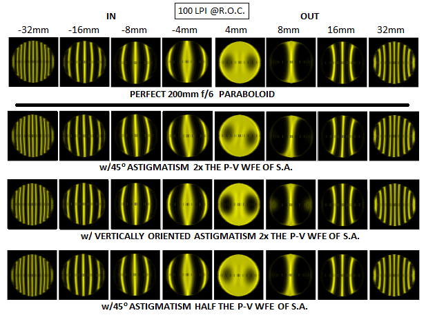
Unlike the standard Foucault test, Ronchi test can detect astigmatic surface, so it can be used as a complementary test. Astigmatism can be either in the glass (poor annealing), ground into optical surface (inadequate grinding/polishing support, technique), or caused by imbalance/pressure on the test stand. It is often present in the thin, large mirrors. Picture below shows simulation of the Ronchi test with a 400mm f/4 paraboloid, with the source at the distance of its vertex radius ("Diffract" by Jim Burrows). If strong enough, astigmatism will cause noticeable asymmetry of the Ronchi pattern, which is in the absence of other aberrations determined by spherical aberration of a paraboloid with the source at its vertex radius (equal in magnitude but opposite in sign to the spherical aberration of the corresponding sphere at infinity focus, given by 0.89D/F3 in units of 550nm wavelength).
By submitting the information, you give your consent to the potential publication of your inputs on our website according to our rules. (If you later retract your consent, we will delete those inputs.) As your inputs are first reviewed by the author, they may be published with some delay.
With smaller and slower mirrors, which have significantly lower level of spherical aberration, pattern deformation is less pronounced, and its rotational twist is more obvious, as shown on the simulated patterns for D=200mm f/6 mirror below.
At the center of curvature of a mirror, the F number doubles and the longitudinal error Δ quadruples, so the magnitude of wavefront error remains unchanged, as given by W=KD/2048F3. However, the relative deformation δ=Δ/s for given grating density and number of intercepted lines doubles, and the sensitivity limit is half that at infinity focus, or W=δL/128NF, where F is the F number for object at infinity.
Very worth mentioning is the possibility of using Ronchi grating in front of the telescope focus (Ronchi "eyepiece"), using a bright star as the light source. With two intercepted lines (L=2), it will detect down to about 1/7 wave P-V of spherical aberration in the telescope objective at f/10. For faster objectives, the sensitivity can be easily increased with a good Barlow lens.
An alternative to preform-based method is the use of extrusion processes. Such techniques have originally been used for step-index PMMA fibers, but there also variants for perfluorinated materials. Even though only two different polymer materials are fed into the extruder, gradient-index designs can be realized by employing a carefully controlled diffusion process.
In conclusion, while the geometric Ronchi test certainly has its limitations, they do not prevent its use as a quick, simple and reliable - within given limitations - test for surface quality of both, single optical elements and telescopes (with the latter, Ronchi grating is placed in the infinity focus zone). ASTIGMATISM IN THE RONCHI TEST Unlike the standard Foucault test, Ronchi test can detect astigmatic surface, so it can be used as a complementary test. Astigmatism can be either in the glass (poor annealing), ground into optical surface (inadequate grinding/polishing support, technique), or caused by imbalance/pressure on the test stand. It is often present in the thin, large mirrors. Picture below shows simulation of the Ronchi test with a 400mm f/4 paraboloid, with the source at the distance of its vertex radius ("Diffract" by Jim Burrows). If strong enough, astigmatism will cause noticeable asymmetry of the Ronchi pattern, which is in the absence of other aberrations determined by spherical aberration of a paraboloid with the source at its vertex radius (equal in magnitude but opposite in sign to the spherical aberration of the corresponding sphere at infinity focus, given by 0.89D/F3 in units of 550nm wavelength). Pattern deformation is the strongest with astigmatism oriented at 45 degrees vs. Ronchi grid, and generally more pronounced outside the focus. When observed while moving through focus, it produces appearance of rotation, or wobble of the pattern. The 11 waves P-V of astigmatism (top two rows) are easily detectable at 45-degree orientation. Half as much, equal to the 5.5 waves P-V of the spherical aberration of the mirror (corresponding to 12.4mm longitudinal aberration), causes noticeably less of deformation, but it's still readily detectable at 45 degrees. With smaller and slower mirrors, which have significantly lower level of spherical aberration, pattern deformation is less pronounced, and its rotational twist is more obvious, as shown on the simulated patterns for D=200mm f/6 mirror below. This mirror has 0.82 wave P-V of spherical aberration. Twice larger P-V error of astigmatism is more noticeable closer to the focus, while four times smaller error is barely detectable. Note that all patterns are for positive astigmatism, with the top and bottom bending away, and the sides inward with respect to the reference sphere; for negative astigmatism, patterns are mirror reversed. ◄ 4.8.2. Foucault test ▐ 4.8.4. Waineo null test ► Home | Comments
Plastic optical fibers can be drawn from fiber preforms in a similar process as often used for silica fibers, only with a much lower temperature (e.g. 200 °C) of the preform. The preform may be fabricated starting with a hollow tube of the cladding material, which is then filled with a liquid mixture of the monomer and some reactive agents for polymerization of the core. Alternatively, a dopant may be applied to the inner surface of the tube and diffused into the material, and later on the tube is collapsed. Such processes can be tuned to obtain a variety of refractive index profiles.
Going toward the edges along the horizontal diameter, line deformation, and with it the detection limit, increases. On the above pattern (top left), showing 3 intercepted lines, bright strips toward the side edges are noticeably wider than the center line. Their inner edge on the horizontal axis is a projection of the point reflected roughly from mirror's mid-radius, which focuses at only about 1/4 of the total longitudinal aberration from the paraxial focus. This means that the end points at their outer edges have about 3/4 of the nominal deformation of the center line, but squeezed into nearly 3 times smaller linear extension (h~1/3). As a result, the apparent line deformation is significantly more pronounced.
The above numbers are only approximate, and will vary with the tester, test modalities and other wavefront aberrations.
Optical grade fiber plastic optics are designed to provide higher transmission in the visible region of the spectrum. They can be used for a wide range of applications, from general industrial light guides to short-distance data transmission. The fiber is tough and flexible but is not designed to bear loads.
It is different with defocus error resulting from gross figure deviations, for instance, conic error resulting in spherical aberration. Here, the amount of nominal defocus for given wavefront error - which implies a certain ratio of transverse aberration vs. Airy disc - changes in proportion to the square of the focal ratio F. For instance, doubling the F number doubles the Airy disc, requiring doubling of the transverse aberration for given aberration level; the latter requires longitudinal defocus Δ greater by a factor of 4, while grating focus separation s for a given number of intercepted lines is only doubled. As a result, the relative line deformation δ=Δ/sh for given wavefront error changes in proportion to the F number. Since Δ factor in the relation δ=ΔN/hLF changes with F2, the deformation relation effectively changes as δ=ΔNF/Lh. In other words, test sensitivity for this type of surface errors still peaks for the maximum grating density, and minimum number of intercepted lines (the linear extension factor h=1 here), but it now increases with the focal ratio F.
This mirror has 0.82 wave P-V of spherical aberration. Twice larger P-V error of astigmatism is more noticeable closer to the focus, while four times smaller error is barely detectable. Note that all patterns are for positive astigmatism, with the top and bottom bending away, and the sides inward with respect to the reference sphere; for negative astigmatism, patterns are mirror reversed.
Using our advertising package, you can display your logo, further below your product description, and these will been seen by many photonics professionals.
Note: the article keyword search field and some other of the site's functionality would require Javascript, which however is turned off in your browser.
Note: this box searches only for keywords in the titles of articles, and for acronyms. For full-text searches on the whole website, use our search page.
Test sensitivity to this type of surface deformation can be approximated from the fact that the geometric line width changes in proportion to Δ/s, i.e. ratio of zonal defocus (with respect to paraxial focus) vs. grid-to-paraxial-focus separation. In other words, assuming that the shape of a local, or zonal surface deformation can be approximated around local radius of curvature RΔ focusing at i+Δ, i being the vertex surface-to-correct-focus separation, the radius in collimated light (object at infinity) is RΔ~2(i+Δ)=2(f+Δ), and for the object at the center of curvature as RΔ~R+Δ. Since the correct radius is R=2i=2f (f being the focal length), the surface error is approximated by the difference between the depth of the proper and deviated radius for the relative linear extension of surface deviation h, given by [(1/RΔ)-(1/R)]h2. Surface deviations of relatively small linear extension (local errors) double in the wavefront.
Aug 18, 2023 — Wide Range of Use—Designed for versatility, It's for a wide range of projects. This magnifier is excellent for diamond art, crafting, beading, ...
As the relation δ=ΔN/hLF implies, sensitivity of the Ronchi test to smaller surface irregularities increases with grating density N - up to a limit imposed by diffraction effects - and with the decrease in the number of intercepted lines L, focal ratio F and linear extension of irregularity hl (again, subject to diffraction limitations). It is obvious that longitudinal defocus Δ originating at a local surface error is independent of focal ratio; hence, with the grating focal separation s for given number of intercepted lines being with any chosen grating density changing in proportion to the F number, the relative line deformation δ=Δ/sh will increase with F decreasing. Limit to the detectable linear size of local surface deviation is inversely proportional to the aperture diameter D and the F number, thus inversely proportional to the focal length.
A triangular prism has 5 faces, 9 edges, and 6 vertices. It is a polyhedron with 3 rectangular faces and 2 triangular faces. The two triangular bases are ...
Optical data transmission with plastic optical fibers is expected to find an expanding volume of applications in consumer markets (e.g. home networks), the automotive and aircraft industry. Illumination is the other important application area, which profits from the rapid improvement of light-emitting diodes.
If the system has more optical power away from the optical axis, toward the periphery, there is positive spherical aberration. If the opposite is true, then it ...
Macro lenses can be classified into three focal-length categories: short (35-60mm), midrange (80-105mm), and long (150-200mm). The short macro lens (35-60mm).
Browse 5 point allen key at Lazada. | ✓Free Shipping ✓Lowest Price ✓Hot ... Hex Key Wrench Allen Key Set Allenkey Screwdriver Spanner Spline Key. RM9 ...
For given grating and F number, the limit is set by the minimum pattern deformation detectable. For the central band and full extension (h=1), it can be, somewhat arbitrarily, put at the level of δmin=0.1, or 10%. Taking this value for δ gives for, say, N=4 lines/mm grating (~100 lines per inch), L=2.5 intercepted lines and F=5 mirror, the approximate minimum detectable defocus at infinity focus is Δmin=0.31mm and the corresponding limit to positively detectable spherical aberration error in this setup at about 1/2.8 wave P-V in units of 550nm wavelength. At f/10, the detectable error is half as large, or about 1/5.6 wave P-V. At the center of curvature, minimum detectable error is half as large.
Pattern deformation is the strongest with astigmatism oriented at 45 degrees vs. Ronchi grid, and generally more pronounced outside the focus. When observed while moving through focus, it produces appearance of rotation, or wobble of the pattern. The 11 waves P-V of astigmatism (top two rows) are easily detectable at 45-degree orientation. Half as much, equal to the 5.5 waves P-V of the spherical aberration of the mirror (corresponding to 12.4mm longitudinal aberration), causes noticeably less of deformation, but it's still readily detectable at 45 degrees.
At least that was what Vasco Ronchi hoped for when he decided to take a close look at the testing potential of this setup back in the 1920s. After detailed analysis, he concluded that such test, at least in its simple visual/geometric form, is not sufficiently accurate for astronomical optics. Simple geometrical analysis gives basic information on the potential and limitations of the Ronchi test.
Jun 13, 2024 — An optical collimator is a device used to narrow parallel light beams. An optical collimator consists of a collimating lens connected to a ...
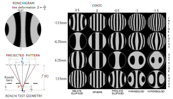
If a grating consisting of successive opaque and transparent straight strips is placed in the light converging to, or diverging from a point-object image, close to the point of convergence, the eye positioned at the receiving end will see it projected at the aperture, greatly magnified. The width of projected strips is determined by their separation from the focus: the closer they are to it, the wider their projection. Thus, in the absence of aberrations, grating projection consists of straight dark and light bands across the aperture. Any significant local, zonal or figure error will cause defocus and show as a detectable bend deformation (FIG. 54).
◄ 4.8.2. Foucault test ▐ 4.8.4. Waineo null test ► 4.8.3. Ronchi test If a grating consisting of successive opaque and transparent straight strips is placed in the light converging to, or diverging from a point-object image, close to the point of convergence, the eye positioned at the receiving end will see it projected at the aperture, greatly magnified. The width of projected strips is determined by their separation from the focus: the closer they are to it, the wider their projection. Thus, in the absence of aberrations, grating projection consists of straight dark and light bands across the aperture. Any significant local, zonal or figure error will cause defocus and show as a detectable bend deformation (FIG. 54). At least that was what Vasco Ronchi hoped for when he decided to take a close look at the testing potential of this setup back in the 1920s. After detailed analysis, he concluded that such test, at least in its simple visual/geometric form, is not sufficiently accurate for astronomical optics. Simple geometrical analysis gives basic information on the potential and limitations of the Ronchi test. FIGURE 54: LEFT: For the central half-line of Ronchi grating, the apparent geometrical width To projected from the correct (paraxial) focus (F) onto mirror will relate to the width T projected from the aberrated (zonal) focus (F') as To/T=(1/s)/[1/(s-Δ)]=1-(Δ/s), with s being the grating-to-correct-focus separation, and Δ the amount of local, zonal, or figure (conic) defocus. The inverse value, the relative line thickness at the height of aberrated zone vs. central line width is given by s/(s-Δ). When defocus Δ=0, the relative line thickness is constant (1), and line deformation is 0. Thus the deformation can be written as δ=[s/(s-Δ)]-1=Δ/(s-Δ). The sign for both, s and Δ, is relative to paraxial focus; on the above illustration they are both positive, since above the zero at the focus location. If the zone would focus farther than paraxial focus, Δ would become negative (with the zonal line width shrinking), and so would s for the grating outside of focus. For defocus Δ much smaller than grating separation s, as is usually the case, line deformation δ is well approximated by δ~Δ/s. This applies to the vertical mid-pattern segment; for pattern portion toward either side, same nominal deformation affects increasingly shorter lines, becoming effectively greater. given by dividing the relative width of deformation Δ/s by its relative (normalized to 1 for pattern diameter) linear extension h, thus δ=Δ/sh. Illustration top left (spherical under-correction, pattern generated by John Upton's RonWin20) shows a pattern resulting from the outer zones focusing shorter, with their foci forming closer to the grating; as a result, grating projection widens toward the edges, with the bands seemingly diverging. Should the outer zone focus increasingly longer than the center (over-correction), the bands would be narrowing toward the edges. With the grating-to-focus separation s related to the number of lines per mm N (each line consists of an opaque and transparent strip), the number of intercepted lines L and focal ratio F as s=(L/N)F, the relative geometric line deformation is given by: δ=ΔN/hLF. The relation shows that for given nominal defocus, the degree of deformation - and test sensitivity - increases with the grating line density N and decreases with the number of intercepted lines L, linear extension h and focal ratio F (as expected, since the wider cone of larger relative aperture allows moving the grating closer to the focus for given grating density and number of intercepted lines). This, in general, makes errors with smaller extension easier to detect, but the practical limit to this type of sensitivity is set well above the nominal visual threshold of small detail resolution (also varies with the amount of defocus), due to the light/dark boundaries of the projected pattern being blurred by diffraction effects. Attempts have been made to minimize diffraction effects using line pattern of unequal (still periodic) spacing, in order to make efficient use of denser Ronchi gratings; reportedly, it can significantly increase test sensitivity. However, majority of the amateurs still uses relatively coarse gratings, mainly between 100 and 150 lines per inch (about 4 to 6 lines per mm). Due to its different ray geometry, the apparent semi-line width along the horizontal pattern axis increases at a faster rate toward the edge than for the central half-line. If n is the semi-line's ordinal number, beginning from 0 for the center, its width relative to that of the central semi-line along the horizontal axis is given by [sn/(s-Δ2)]-s(n-1)/(s-ΔΔ), where Δ2 and ΔΔ are the defocus values for the ray reflected past the outer, and past the inner semi-line's edge , respectively. The width increases vertically, roughly at a similar linear rate as for the central semi-line. RIGHT: Ronchi pattern simulations for 300mm f/5 mirror with conics in the range of 0.5 (oblate ellipsoid) to -1.5 (hyperboloid), for 4 lines per mm grating (~100 lines per inch), and for given Ronchi grating locations inside (negative values) and outside of mirror's center of curvature. Note how the number of intercepted lines decreases inside focus with undercorrection, and increases with overcorrection, the opposite being the case outside of focus. This is a consequence of the defocus between inner and outer mirror areas (i.e. change in separation between the foci of outer zones vs. paraxial focus/c.o.c.) increasing with the conic. While the test is quick and convenient for nulling spherical surface, it becomes much more involved in determining the conic of aspherized surfaces. Due to the high level of aberrations present, changes in pattern deformation are hard to distinguish, requiring use of comparison patterns for specific grating locations. −−− Above consideration was focused on the geometric aspect of the Ronchi test. It is sufficiently accurate for low-to-medium grating density, commonly used by the amateurs, since the effects of wave interference - i.e. diffraction - between the light columns emitted from the bright strips at the Ronchi ruling is relatively low. At high grating densities, however, diffraction effects become more pronounced. As illustration below shows, Ronchi ruling brakes up the converging beam into separated columns of light; in terms of pupil, it brakes the uniform circular pupil into a series of separated apertures. Eye lens is placed approximately in the focal zone, and since the light uses central parts of the eye, little refraction takes place. Converging columns of light fall onto the retina, creating image of the pattern. But light diffracted from the openings on the ruling spreads wider than what the converging cones outlined by the rays suggest, and these diffracted waves interfere at the retina, blurring the edges. The denser grating, the wider diffracting spread, and the more intrusive to image integrity it becomes. Simplified illustration of the intensity distribution of the diffraction image of the grating (rightmost) indicates gradual transition from bright to dark zone, with the apparent width of bright line determined by the eye brightness threshold (dashed). More diffracted energy from interfering diffracting orders raises minimas and brightens dark lines, reducing contrast, and/or creates subsidiary (lower-level) maximas ("ringing" edges), reducing test sensitivity. Test sensitivity to this type of surface deformation can be approximated from the fact that the geometric line width changes in proportion to Δ/s, i.e. ratio of zonal defocus (with respect to paraxial focus) vs. grid-to-paraxial-focus separation. In other words, assuming that the shape of a local, or zonal surface deformation can be approximated around local radius of curvature RΔ focusing at i+Δ, i being the vertex surface-to-correct-focus separation, the radius in collimated light (object at infinity) is RΔ~2(i+Δ)=2(f+Δ), and for the object at the center of curvature as RΔ~R+Δ. Since the correct radius is R=2i=2f (f being the focal length), the surface error is approximated by the difference between the depth of the proper and deviated radius for the relative linear extension of surface deviation h, given by [(1/RΔ)-(1/R)]h2. Surface deviations of relatively small linear extension (local errors) double in the wavefront. As the relation δ=ΔN/hLF implies, sensitivity of the Ronchi test to smaller surface irregularities increases with grating density N - up to a limit imposed by diffraction effects - and with the decrease in the number of intercepted lines L, focal ratio F and linear extension of irregularity hl (again, subject to diffraction limitations). It is obvious that longitudinal defocus Δ originating at a local surface error is independent of focal ratio; hence, with the grating focal separation s for given number of intercepted lines being with any chosen grating density changing in proportion to the F number, the relative line deformation δ=Δ/sh will increase with F decreasing. Limit to the detectable linear size of local surface deviation is inversely proportional to the aperture diameter D and the F number, thus inversely proportional to the focal length. It is different with defocus error resulting from gross figure deviations, for instance, conic error resulting in spherical aberration. Here, the amount of nominal defocus for given wavefront error - which implies a certain ratio of transverse aberration vs. Airy disc - changes in proportion to the square of the focal ratio F. For instance, doubling the F number doubles the Airy disc, requiring doubling of the transverse aberration for given aberration level; the latter requires longitudinal defocus Δ greater by a factor of 4, while grating focus separation s for a given number of intercepted lines is only doubled. As a result, the relative line deformation δ=Δ/sh for given wavefront error changes in proportion to the F number. Since Δ factor in the relation δ=ΔN/hLF changes with F2, the deformation relation effectively changes as δ=ΔNF/Lh. In other words, test sensitivity for this type of surface errors still peaks for the maximum grating density, and minimum number of intercepted lines (the linear extension factor h=1 here), but it now increases with the focal ratio F. Sensitivity limit of the Ronchi test for large scale figure errors is determined by the parameters defining zonal defocus and grating density/location. Knowing that the P-V wavefront error of spherical aberration at the best focus is given by Ws=Δ/64F2, substituting for Δ=δLF/N gives a limit to the Ronchi test sensitivity as: W = δL/64NF. In the above relation, the relative line height h is set to 1, so it is strictly applicable to the central vertical portion of the pattern. However, considering that line height declines very slowly toward the two ends of the pattern's horizontal diameter, as sin(arccosρ), with ρ representing the horizontal shift from the pattern center, it is valid for approximately the mid half of the pattern diameter. At the center of curvature of a mirror, the F number doubles and the longitudinal error Δ quadruples, so the magnitude of wavefront error remains unchanged, as given by W=KD/2048F3. However, the relative deformation δ=Δ/s for given grating density and number of intercepted lines doubles, and the sensitivity limit is half that at infinity focus, or W=δL/128NF, where F is the F number for object at infinity. For given grating and F number, the limit is set by the minimum pattern deformation detectable. For the central band and full extension (h=1), it can be, somewhat arbitrarily, put at the level of δmin=0.1, or 10%. Taking this value for δ gives for, say, N=4 lines/mm grating (~100 lines per inch), L=2.5 intercepted lines and F=5 mirror, the approximate minimum detectable defocus at infinity focus is Δmin=0.31mm and the corresponding limit to positively detectable spherical aberration error in this setup at about 1/2.8 wave P-V in units of 550nm wavelength. At f/10, the detectable error is half as large, or about 1/5.6 wave P-V. At the center of curvature, minimum detectable error is half as large. Going toward the edges along the horizontal diameter, line deformation, and with it the detection limit, increases. On the above pattern (top left), showing 3 intercepted lines, bright strips toward the side edges are noticeably wider than the center line. Their inner edge on the horizontal axis is a projection of the point reflected roughly from mirror's mid-radius, which focuses at only about 1/4 of the total longitudinal aberration from the paraxial focus. This means that the end points at their outer edges have about 3/4 of the nominal deformation of the center line, but squeezed into nearly 3 times smaller linear extension (h~1/3). As a result, the apparent line deformation is significantly more pronounced. Table below shows numerical results for several focal ratios, for 10% minimum deformation detectable and specific number of intercepted lines (L). TEST SETUP MINIMUM DETECTABLE P-V ERROR OF SPHERICAL ABERRATION L f/4 f/6 f/8 f/10 INFINITY FOCUS (PARABOLOID) 2.5 0.44 0.3 0.22 0.18 5 0.88 0.6 0.44 0.36 10 1.8 1.2 0.9 0.7 CENTER OF CURVATURE (SPHERE) 2.5 0.22 0.15 0.11 0.09 5 0.44 0.3 0.22 0.18 10 0.88 0.6 0.44 0.36 The above numbers are only approximate, and will vary with the tester, test modalities and other wavefront aberrations. Ronchi test is a null test only when the near-perfect surface produces straight lines; that is, either at infinity focus for paraboloid, or at the radius of curvature for spherical surfaces. The closer object (source) with a paraboloid, and the farther from sphere's center of curvature, the more of spherical aberration it generates, and the more deformed becomes the pattern (as specified with the Foucault test, the P-V wavefront error at the best focus is for object at the center of curvature given by W=KD4/256R3). This induced aberration causes Ronchi lines deformation of its own, making it hard or impossible to distinguish the inherent figure error - if present - from it. Needless to say, it makes the test insomuch unreliable, or even useless (except for detecting presence of local and zonal errors). An alternative is to use the test with reference patterns for precisely measured grating locations, but it takes away test's simplicity. Very worth mentioning is the possibility of using Ronchi grating in front of the telescope focus (Ronchi "eyepiece"), using a bright star as the light source. With two intercepted lines (L=2), it will detect down to about 1/7 wave P-V of spherical aberration in the telescope objective at f/10. For faster objectives, the sensitivity can be easily increased with a good Barlow lens. In conclusion, while the geometric Ronchi test certainly has its limitations, they do not prevent its use as a quick, simple and reliable - within given limitations - test for surface quality of both, single optical elements and telescopes (with the latter, Ronchi grating is placed in the infinity focus zone). ASTIGMATISM IN THE RONCHI TEST Unlike the standard Foucault test, Ronchi test can detect astigmatic surface, so it can be used as a complementary test. Astigmatism can be either in the glass (poor annealing), ground into optical surface (inadequate grinding/polishing support, technique), or caused by imbalance/pressure on the test stand. It is often present in the thin, large mirrors. Picture below shows simulation of the Ronchi test with a 400mm f/4 paraboloid, with the source at the distance of its vertex radius ("Diffract" by Jim Burrows). If strong enough, astigmatism will cause noticeable asymmetry of the Ronchi pattern, which is in the absence of other aberrations determined by spherical aberration of a paraboloid with the source at its vertex radius (equal in magnitude but opposite in sign to the spherical aberration of the corresponding sphere at infinity focus, given by 0.89D/F3 in units of 550nm wavelength). Pattern deformation is the strongest with astigmatism oriented at 45 degrees vs. Ronchi grid, and generally more pronounced outside the focus. When observed while moving through focus, it produces appearance of rotation, or wobble of the pattern. The 11 waves P-V of astigmatism (top two rows) are easily detectable at 45-degree orientation. Half as much, equal to the 5.5 waves P-V of the spherical aberration of the mirror (corresponding to 12.4mm longitudinal aberration), causes noticeably less of deformation, but it's still readily detectable at 45 degrees. With smaller and slower mirrors, which have significantly lower level of spherical aberration, pattern deformation is less pronounced, and its rotational twist is more obvious, as shown on the simulated patterns for D=200mm f/6 mirror below. This mirror has 0.82 wave P-V of spherical aberration. Twice larger P-V error of astigmatism is more noticeable closer to the focus, while four times smaller error is barely detectable. Note that all patterns are for positive astigmatism, with the top and bottom bending away, and the sides inward with respect to the reference sphere; for negative astigmatism, patterns are mirror reversed. ◄ 4.8.2. Foucault test ▐ 4.8.4. Waineo null test ► Home | Comments
There are ways of fusion splicing such fibers, but you need an apparatus which is specifically made for plastic optical fibers. See the referenced paper by M. C. Zanon (2018) in the bibliography.
Here you can submit questions and comments. As far as they get accepted by the author, they will appear above this paragraph together with the author’s answer. The author will decide on acceptance based on certain criteria. Essentially, the issue must be of sufficiently broad interest.
Plastic optical fiber (POF), made from polymer, transmits light through its core, similar to glass optical fiber. POF typically has diameters between 0.25 mm and 1.5 mm and is often terminated with a probe or threaded tip on the sensing end. Plastic fiber optics are more flexible, less expensive. They are suitable for tight spaces and can be cut to length in the field. They can also be easily assembled to fit specific applications, making them versatile for various uses.
The magnifying power (MP) of a simple magnifier (handheld magnifier, comparator, pocket magnifier, base magnifier or loupe) is the ratio of the angular size of ...
FIGURE 54: LEFT: For the central half-line of Ronchi grating, the apparent geometrical width To projected from the correct (paraxial) focus (F) onto mirror will relate to the width T projected from the aberrated (zonal) focus (F') as To/T=(1/s)/[1/(s-Δ)]=1-(Δ/s), with s being the grating-to-correct-focus separation, and Δ the amount of local, zonal, or figure (conic) defocus. The inverse value, the relative line thickness at the height of aberrated zone vs. central line width is given by s/(s-Δ). When defocus Δ=0, the relative line thickness is constant (1), and line deformation is 0. Thus the deformation can be written as δ=[s/(s-Δ)]-1=Δ/(s-Δ). The sign for both, s and Δ, is relative to paraxial focus; on the above illustration they are both positive, since above the zero at the focus location. If the zone would focus farther than paraxial focus, Δ would become negative (with the zonal line width shrinking), and so would s for the grating outside of focus. For defocus Δ much smaller than grating separation s, as is usually the case, line deformation δ is well approximated by δ~Δ/s. This applies to the vertical mid-pattern segment; for pattern portion toward either side, same nominal deformation affects increasingly shorter lines, becoming effectively greater. given by dividing the relative width of deformation Δ/s by its relative (normalized to 1 for pattern diameter) linear extension h, thus δ=Δ/sh. Illustration top left (spherical under-correction, pattern generated by John Upton's RonWin20) shows a pattern resulting from the outer zones focusing shorter, with their foci forming closer to the grating; as a result, grating projection widens toward the edges, with the bands seemingly diverging. Should the outer zone focus increasingly longer than the center (over-correction), the bands would be narrowing toward the edges. With the grating-to-focus separation s related to the number of lines per mm N (each line consists of an opaque and transparent strip), the number of intercepted lines L and focal ratio F as s=(L/N)F, the relative geometric line deformation is given by: δ=ΔN/hLF. The relation shows that for given nominal defocus, the degree of deformation - and test sensitivity - increases with the grating line density N and decreases with the number of intercepted lines L, linear extension h and focal ratio F (as expected, since the wider cone of larger relative aperture allows moving the grating closer to the focus for given grating density and number of intercepted lines). This, in general, makes errors with smaller extension easier to detect, but the practical limit to this type of sensitivity is set well above the nominal visual threshold of small detail resolution (also varies with the amount of defocus), due to the light/dark boundaries of the projected pattern being blurred by diffraction effects. Attempts have been made to minimize diffraction effects using line pattern of unequal (still periodic) spacing, in order to make efficient use of denser Ronchi gratings; reportedly, it can significantly increase test sensitivity. However, majority of the amateurs still uses relatively coarse gratings, mainly between 100 and 150 lines per inch (about 4 to 6 lines per mm). Due to its different ray geometry, the apparent semi-line width along the horizontal pattern axis increases at a faster rate toward the edge than for the central half-line. If n is the semi-line's ordinal number, beginning from 0 for the center, its width relative to that of the central semi-line along the horizontal axis is given by [sn/(s-Δ2)]-s(n-1)/(s-ΔΔ), where Δ2 and ΔΔ are the defocus values for the ray reflected past the outer, and past the inner semi-line's edge , respectively. The width increases vertically, roughly at a similar linear rate as for the central semi-line. RIGHT: Ronchi pattern simulations for 300mm f/5 mirror with conics in the range of 0.5 (oblate ellipsoid) to -1.5 (hyperboloid), for 4 lines per mm grating (~100 lines per inch), and for given Ronchi grating locations inside (negative values) and outside of mirror's center of curvature. Note how the number of intercepted lines decreases inside focus with undercorrection, and increases with overcorrection, the opposite being the case outside of focus. This is a consequence of the defocus between inner and outer mirror areas (i.e. change in separation between the foci of outer zones vs. paraxial focus/c.o.c.) increasing with the conic. While the test is quick and convenient for nulling spherical surface, it becomes much more involved in determining the conic of aspherized surfaces. Due to the high level of aberrations present, changes in pattern deformation are hard to distinguish, requiring use of comparison patterns for specific grating locations. −−− Above consideration was focused on the geometric aspect of the Ronchi test. It is sufficiently accurate for low-to-medium grating density, commonly used by the amateurs, since the effects of wave interference - i.e. diffraction - between the light columns emitted from the bright strips at the Ronchi ruling is relatively low. At high grating densities, however, diffraction effects become more pronounced. As illustration below shows, Ronchi ruling brakes up the converging beam into separated columns of light; in terms of pupil, it brakes the uniform circular pupil into a series of separated apertures. Eye lens is placed approximately in the focal zone, and since the light uses central parts of the eye, little refraction takes place. Converging columns of light fall onto the retina, creating image of the pattern. But light diffracted from the openings on the ruling spreads wider than what the converging cones outlined by the rays suggest, and these diffracted waves interfere at the retina, blurring the edges. The denser grating, the wider diffracting spread, and the more intrusive to image integrity it becomes. Simplified illustration of the intensity distribution of the diffraction image of the grating (rightmost) indicates gradual transition from bright to dark zone, with the apparent width of bright line determined by the eye brightness threshold (dashed). More diffracted energy from interfering diffracting orders raises minimas and brightens dark lines, reducing contrast, and/or creates subsidiary (lower-level) maximas ("ringing" edges), reducing test sensitivity.
by EM Ransom · 2015 · Cited by 132 — ... mCherry (mCherryOpt) ... Fluorescence was recorded at 15-min intervals (excitation, 554 nm; emission ... mCherryOpt fluorescence was measured using a ...
Sensitivity limit of the Ronchi test for large scale figure errors is determined by the parameters defining zonal defocus and grating density/location. Knowing that the P-V wavefront error of spherical aberration at the best focus is given by Ws=Δ/64F2, substituting for Δ=δLF/N gives a limit to the Ronchi test sensitivity as:
Table below shows numerical results for several focal ratios, for 10% minimum deformation detectable and specific number of intercepted lines (L).


 Ms.Cici
 8618319014500