
The 3 Best Webcams of 2024 | Reviews by Wirecutter - high resolution usb camera
There are all kinds of cameras that can be used with a microscope. Key experimental considerations are the sensitivity, resolution, field of view and speed of a camera. For a detailed explanation, see our articles on these subjects.
Figure 2: Convex vs concave lenses. A convex lens is thicker at the center than the edge and will focus a beam of light to a point a certain distance in front of the lens (the focal length). A concave lens is the opposite, being thicker at the edge than the center and spreading out a beam of light. Microscopes use convex lenses in order to focus light. Image from http://clubsciencekrl.blogspot.com/.
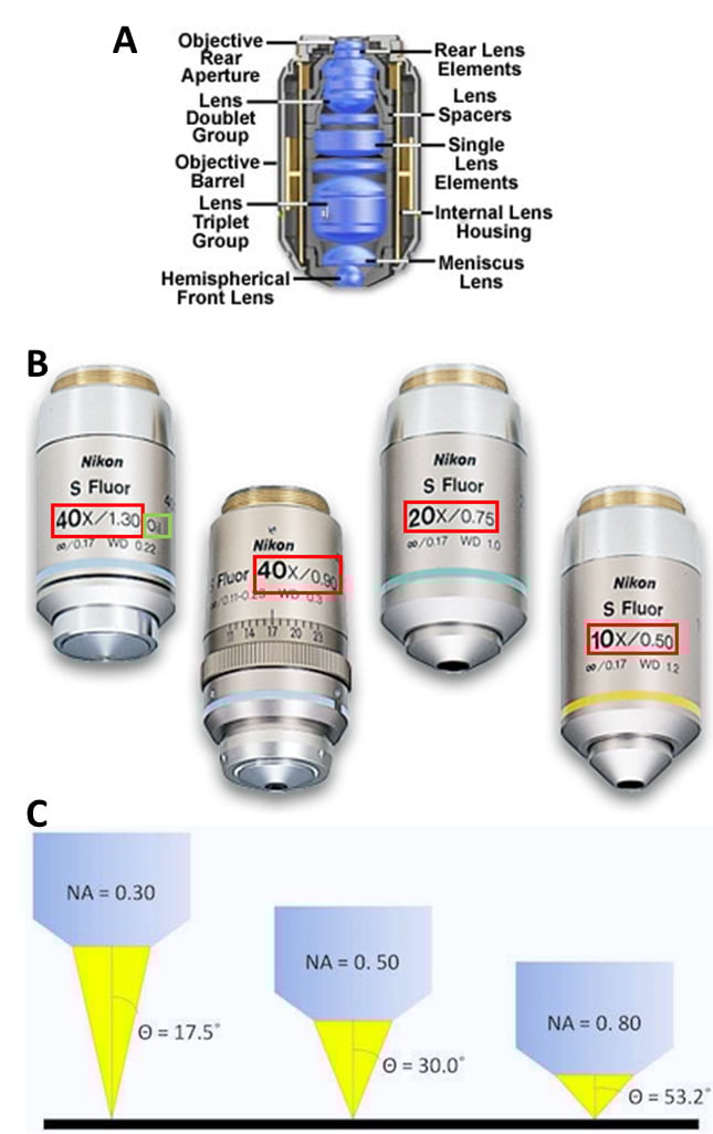
Microscope objectives contain lenses but are not as simple as the lenses seen in Fig.2, making them complex lenses (Fig.3A). While the overall effect can be magnification, these lenses are carefully designed to control a variety of aspects of lenses, such as working distance, and the ability to correct problems such as aberrations. Objectives are characterized by two factors: magnification and numerical aperture (NA). Objective magnification ranges from 2x to 100x (and is combined with the eyepiece magnification), magnifying the sample 2-fold to 100-fold respectively (Fig.3B). NA is related to the focal length of the lens, namely what angle light exits/enters the objective, as this affects the resolution (Fig.3C, read our app note on resolution and NA for more). See Fig.3 for more information.
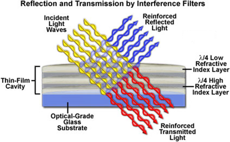
Figure 7: Modern color-selecting interference filter. The various layers on top of the glass substrate acting in total reflect blue light while allowing transmission of the red light. Taken from http://zeiss-campus.magnet.fsu.edu/articles/lightsources/leds.html
Putting the illumination source close to the sample limits control of light intensity and illumination field of view. Köhler imaged the light source to a focal length from the condenser lens, as illustrated in Fig.5. This provides control of the field of illumination, with a field stop in the middle of the imaging component and an aperture stop 1f away from the condenser. The aperture stop is a highly significant aspect of the design; allowing easy control of the light power to the sample. These stops usually have levers allowing the user to manually adjust the illumination area (field stop) and power (aperture stop) being delivered to the sample.
Microscope
The focal length of a microscope objective lens needs to be very small, as the objective is often very close to the sample. Typically, the higher the magnification, the closer the objective needs to be.
Köhler invented a focusable illumination system that allowed control of the field size, the power and the angle of illumination while scrambling the structure of the light source projected on the sample. He took advantage of the property of a lens to convert the lateral structure into parallel rays to do this. Putting an illumination source at the focal point of the lens transforms the output into uniform light rays on the other side, scrambling any structure inherent in the source. Multiple points emitting from the light source all end up scrambled and traveling in parallel rays after exiting the lens
4. Reichman, J. 2017 Handbook of Optical Filters for Fluorescence Microscopy. Chroma Technology Company Bellows Falls, Vermont 05101-3119 (https://www.chroma.com/sites/default/files/HandbookofOpticalFilters.pdf)
With a microscope, a relay lens system replaces the single lens; an objective and an eyepiece work in tandem to project the image of the object onto the eye, or ...
The irreducible divergence (full angle) is given by the expression 4M2λ/πd where d is the diameter of the laser beam measured at its waist. For reasons given above, this figure is often lower than the ‘raw’ divergence of the laser beam itself. To a first order approximation, the above expression holds true even if the laser beam is expanded or reduced by telescopes and the like.
Figure 8: Transmittance versus wavelength for various filter types. In the LP example, red light would pass through and blue light would be reflected. In the SP example, blue light would pass and red light reflected. In the BP example, both blue and red light is reflected while green light is transmitted. Taken from Basic Aspects of Light Filters Molecular Expressions Optical Microscopy Primer https://micro.magnet.fsu.edu/primer/lightandcolor/filtersintro.html
The useful life of each of these sources varies between a few hundred hours for mercury arc lamps, to 1000-2000 hours for mercury/metal halide and halogen lamps.
Function ofdiopter adjustment inmicroscope
Figure 1: Cut-away image of a modern microscope. There are two independent illumination pathways; 1) Epi-illumination reflected through the objective lens to illuminate the sample from above, 2) Trans-illumination focused by a separate condenser lens to illuminate the sample along the imaging axis of the microscope. There is a single imaging pathway for light, from the sample, through the objective and tube lenses and into the detector/camera or eyepiece. Derived from an image of a microscope on the Olympus Microscopy Primer and modified by the author.
Two illumination methods, critical or Köhler, are commonly used to illuminate the sample in microscopy. The primary difference is whether they copy the structure (critical) or scramble the structure (Köhler) of the illumination source at the sample. As Köhler illumination is more frequently used, it will be covered in this article.
Filters are commonly referred by the nature of their transmission, and the wavelength where they switch from transmission to reflection, as illustrated in Fig.8. A 500 nm short pass (SP) filter would transmit light bluer than 500 nm and reflect light redder than 500 nm. In contrast, a 500 nm long-pass (LP) filter will transmit light longer than 500 nm, reflecting light of shorter wavelengths.
Most microscopes have optical exit ports with a diameter of around 18-25 mm. Using no magnification (1x objective), the image would, therefore, cover 18-25 mm of the sample. Given the fixed size of the image, camera sensors with diagonal dimensions greater than the microscope camera port would have pixels with no light falling on them. Therefore, it is important to match the field of view of the camera with the maximum field of view of the microscope.
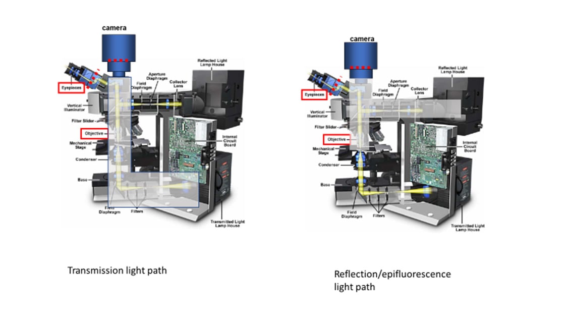
Figure 4: Transmission/trans-fluorescence and reflection/epi-fluorescence microscopy light paths in a model microscope. The gray area indicates the light paths involved for each mode. Derived from an image of a microscope on the Olympus Microscopy Primer and modified by the author.
Measuring the beam in the focal plane of the lens yields the beam’s ‘raw’ divergence, simply by dividing the beam diameter in the focal plane by the focal length. Since we only know for sure what the laser beam diameter is near its output aperture, this figure tells us little about the beam quality. We do not know the position of the waist of the original laser beam or its size. In many real lasers, it can be located behind the laser (or sometimes well in front of it) and is thus often smaller than the laser beam diameter measured at its output aperture. Only the true waist diameter can be combined with the divergence to give M2.
6. Spring, K.R., Parry-Hill, M., Burdett, C.A., Sutton, R. T., Fellers, T.J. and Davidson, M.W. Laser Fundamentals in the Olympus Microscopy Primer website (https://www.olympus-lifescience.com/en/microscope-resource/primer/lightandcolor/laserhome/)
Illuminate definition: To provide or brighten with light.
A true measure of the quality of a laser beam is the parameter known as M2, also referred to as a number of ‘times diffraction limited’. It describes how a beam will diverge compared to a theoretically ‘perfect’ laser beam of the same wavelength and initial size that has the lowest possible divergence given by diffraction theory. A theoretically perfect laser beam must have a Gaussian intensity distribution whereas most real laser beams do not. We therefore have to make some approximations when talking about M2. We measure the laser beam diameter as the diameter of a circle containing 1/e2 or about 87% of the power or energy and the divergence angle as the full angle of the cone containing the same power or energy. We use an ellipse to make the same figures where the beam is not nominally circular. Real lasers can have M2 values ranging from very little more than 1 (the theoretical minimum) to several tens or even hundreds. Many practical applications require the lowest possible value. The optical set up depicted here can be used to measure both the beam divergence and the M2 value of a real laser. A lens of focal length 1 or 2m is typically used, along with attenuation optics and the beam is imaged using a CCD and software.
Fluorescence microscopy uses reflection or epi-fluorescence geometry, where the objective serves as both the illumination condenser and the imaging lens. The illumination light is passed through the objective and the detected light is passed backward through the objective and split off to a camera or eyepiece. One benefit of this approach is that light that doesn't interact with the sample travels away from the detector, maximizing separation of illumination light from fluorescent emission. The transmission and epi-fluorescence light paths are illustrated in Figure 4.
Enhance your spotlight or tungsten lamp with our Large Glass Fresnel Lens, available in 200mm, 250mm, and 300mm sizes. Crafted from durable glass, ...
By looking in the vicinity of the focal plane for a minimum diameter spot, the waist as transformed by the lens, we can gain much more useful information. For real lasers, the waist is usually located near the focal plane and usually a little way after it. Note that the original beam divergence is eliminated in the expression that gives M2. It is expressed in terms of the beam diameter at the waist, the diameter of the beam at the lens and the distance of the waist from the lens. All these parameters are relatively easily measured. The focal length of the lens and the beam diameter at the lens need to be chosen such that the waist is much smaller than the beam diameter at the lens. Technically speaking, to achieve accurate measurements, the waist must be much greater than its Rayleigh range from the lens. This value is given by πd02/4λM2.
There are a variety of lamps, light-emitting diodes (LEDs) and lasers that can be used to illuminate the sample in the microscope. Typical lamps used for illumination include:
Partsof microscopeand itsfunction
A lens is an optical device that can refract light. The refraction depends on the shape of a lens, which is typically convex or concave. For the purposes of microscopy, convex lenses are used for their ability to focus light at a single point. This is how the human eye works, with the convex biological lens focusing light on the back of your eye where rod and cone cells can detect it. Microscopes borrowed this idea, using convex lenses to focus light towards a point that is f distance away from the lens. This distance is known as the focal length of the lens and depends on the shape. Lens shapes can be seen in Fig.2. It should be noted that these lenses are symmetrical and will have the same effect on light from either direction.
The aperture stop is the part of the imaging system that limits the range of angles of light the lens can collect from the sample. This range of angles defines the lens NA and therefore the system resolution, the ability to detect two objects as different. Most microscope objectives are designed such that the aperture stop is the Objective Rear Aperture, as seen in Fig.3A. This ensures that the objective defines the system resolution and that the resolution is the same across the entire field of view.
By combining the properties of SP and LP filters, bandpass (BP) filters were created. A SP 550 nm filter combined with a LP 500 nm filter would transmit light only between 500-550 nm. BP filters are usually described by their center wavelength and the allowed wavelengths to either side. A hypothetical SP550, LP500 filter combination is commonly referred to as BP 525d25, a BP centered at 525 nm with 25 nm transmission permitted to either side (Reichman, 2017).
In the discussion above, the beam divergence as measured in the focal plane of our lens frequently contains some reducible elements. These can include sphericity imposed by lensing in an amplifier after the rod (and not fully compensated by the beam expanding telescope) or sphericity resulting from improper collimation of an unstable resonator; with a fixed length and a finite number of resonator mirror curvatures, it is often impossible to achieve perfect collimation. With proper beam control after the laser, such as the transmitting optics in a LIDAR system, or the focusing lens in a machining head, this sphericity can be eliminated and the irreducible element, as predicted by M2, will determine respectively the angular resolution of the LIDAR system or the spot size at a work piece.
The Thermo Scientific™ DELTA™ Q Isotope Ratio Mass Spectrometer (IRMS) represents the next evolutionary leap forwards in isotope analysis, combining ...
Function ofobjective lens inmicroscope
The output of most microscopes is an image about 2 cm across, so this is typically magnified again in order to fill the field of view of the eyes. Eyepieces, another magnification system, give between 10x to 30x magnification on top of that provided by the objective and microscope. In combination with the lens in the eye, this magnifies the image to the retina at a useful scale, so that the human eye may resolve and observe objects even as small as cells (~10 µm).
Filters are optical components that can transmit certain wavelengths of light while reflecting others. Color selection is critical for fluorescence imaging. An example of optical filtering is shown in Fig.7.
3. Parry-Hill, M.J., Vogt, K.M, Griffin J.D., and Davidson, M.W. Matching Camera to Microscope Resolution in the MicroscopyU website (https://www.microscopyu.com/tutorials/matching-camera-to-microscope-resolution)
In the fluorescence microscope, a combination of excitation BP filter, a LP dichroic filter and an emission BP filter are organized into a cube holder to provide high-intensity excitation light to the sample and efficiently isolate emission light before steering it off to the camera.
Eyepiecelensmicroscope
LED light sources are powerful enough to compete with xenon and mercury/metal halide lamps as illumination sources for fluorescence imaging. Each LED has a unique color, so LED broad band sources are derived from arrays of multiple individual diodes of relatively narrow spectra. LED sources have lifetimes of 10,000+ hours of use and are highly energy-efficient, making them very economical over long term use. They can be turned on and off quickly, over nanoseconds, making them useful for experiments requiring tight control of illumination. The spectral distribution of an example LED light source is illustrated in Fig.6.
Various microscopy methods detect specific interactions between light and the sample. Methods that image scattered or absorbed light focus illumination light to the sample using a separate illumination lens and imaging objective. The focusing illumination lens is referred to as a condenser, with its own properties of working distance, NA, etc.
Pixel size is key to being able to image with the full information content provided by the optics. Camera pixels are square and usually 3-24 µm along the edge. Generally speaking, cameras with smaller pixels allow for higher resolution imaging whereas cameras with larger pixels have a larger surface area for photon collection making them more sensitive.
Lasers provide light with highly specific wavelengths. For example, the light generated by a helium-neon (HeNe) laser has a color of 632.8 nm. Unlike the other light sources discussed here, lasers provide coherent light. Coherence indicates that the light is highly structured, with all the peaks and troughs of the light wave occurring at the same time and place. Coherence is necessary when focusing light to a diffraction-limited point, but also complicates widefield illumination due to its tendency for positive and negative interference. This self-interference can often be detected as a speckle pattern in an expanded laser beam.
High-Paying Jobs at Edmund Optics ; Principal Systems Engineer. $130K — $173K * · Tucson, AZ 85705 ; Manager of Strategic Sourcing Engineering. $101K — $151K *.
UVLens shows you when you need to take care and when you can safely enjoy the sun. ... See the UV index forecast for the day, see when it's safe to be outside and ...
The parts of the microscope discussed here work in concert to send light to the sample and take the light from the sample and magnify it up to the detector for collection. Aperture stops, usually in the objective, limit the microscope resolution. Field stops limit the area illuminated or detected. Components such as objectives, light sources, filters, and cameras all must be considered to get the best possible image.
A camera pixel is the individual light-measuring unit in the camera, and the camera's sensor has arrays of pixels to measure the light across the field of view. A camera might have as few as 128×128 pixels, or as many 5000×3000 (15 million pixels, or 15 megapixels) or more. Since microscope camera ports commonly have the same approximate size, cameras with larger pixel arrays usually have smaller individual pixels.
Function ofarm inmicroscope
The field stop limits the area that can be imaged. This can't be bigger than the diameter of the tube lens. At best, the area imaged is the diameter of this lens divided by the magnification. If the internal lens has a diameter of 25 mm and the magnification is 100x, one should see a circle with a diameter of 250 µm of the sample. Things suc h as light modifying elements, or the detector itself, can easily reduce the field of view that is collected.
At its core, a typical microscope is essentially a box designed to hold two lenses in precise positions so that light can be accurately magnified from the sample to the detector. The first of these two lenses is the objective lens, which is located close to the sample, moves when the focus dial is turned and has useful information such as magnification written on its side. The second is commonly referred to as the tube/collector lens, which is buried deep within the body of the microscope and rarely seen.
There are always constraints to the area to be imaged and the detailed information a microscope provides. There are physical blocks in the light path, typically named stops, diaphragms, or apertures. Here, the term stop will be used. For the imaging path, they may or may not be adjustable by the user, but as discussed later, the same concepts apply to the illumination optics.
Function ofbody tube inmicroscope
Oct 17, 2024 — Raman scattering is perhaps most easily understandable if the incident light is considered as consisting of particles, or photons (with energy ...
by KP Zetie · 2000 · Cited by 185 — Abstract. The Mach-Zehnder interferometer is a particularly simple device for demonstrating interference by division of amplitude. A light beam is first split ...
In some cases, our waist will be located in the focal plane of the lens. Only then can we say that the laser is truly collimated and only then can the aperture – divergence product be used to determine the beam quality. In many practical cases, this does not hold true.
This anti-reflective film reduces unpleasant reflections on tablets and laptops with a glossy coating (glare), which can be caused by sunlight falling on the ...
5. Spring, K.R., Parry-Hill, M. & Davidson, M.W. Geometrical Construction of Ray Diagrams in the Olympus Microscopy Primer website (https://www.olympus-lifescience.com/en/microscope-resource/primer/java/components/characteristicrays/)
Figure 3: On microscope objective lenses. A) An example of the location of lenses in an objective cross-section, making this a complex lens. B) Different Nikon Super Fluor objectives, ranging from 10x to 40x. The red boxes show the magnification / NA of the lens, with the air 40x having an NA of 0.90 and the oil-immersion 40x having an NA of 1.30, showing the effect of the imaging medium on the NA (the denser the better). C) How different NA affects the illumination of the sample, the higher the NA the greater the angle of light from the objective, and the greater the maximum resolution.
What iseyepieceinmicroscope
2. Davidson, M.W. Koehler Illumination in the Zeiss Basic Resources website (https://w ww.zeiss.com/microscopy/us/solutions/reference/basic-microscopy/koehler-illumination.html)
Bigger pixels have benefits to sensitivity. Indirectly, they also have benefits on the total time it takes to get the information out to the computer. Total readout time is dependent on camera architecture, with CMOS being faster than CCD, but also on the total number of pixels in the camera. In general, a camera with bigger but fewer pixels will be ready for the next exposure faster that a camera with more, smaller pixels.
TLC Eyewear in Canton, MA. TLC Eyewear is a full-service, family optical care shop offering complete eye care. With 2 locations we're able to service our ...
Figure 6: Normalized intensity versus wavelength plot of LEDs useful for fluorescence microscopy. Taken from http://www.fluorescencemicroscopy.it/en/illumination.html
These components are responsible for the magnification, resolution, and field of view inherent in the microscope. In this article, the details of microscope components and anatomy are explained in relation to how they contribute to providing the best possible image. In order to see the arrangement of these components, see Fig.1.
Figure 5: Köhler illumination optics. The lamp has a zig-zag filament on the left-hand housing, and the sample is to the right. Working from left to right, light from the lamp is imaged to a position 1F from the principal plane of the condenser. Light with structure entering the condenser is scrambled upon delivery to the sample. The field stop provides control of the area in the sample that is illuminated. The aperture stop controls the range of angles, and the power, of the illumination. The light path from a central point of the filament at left to the sample at right is highlighted in orange. Derived from Biomedical Engineering Dept at Boston University.


 Ms.Cici
 8618319014500