
Swagelok ® Tube Fittings and Adapters - the view tube
Apparatus description: Helium-Neon laser (Metrologic): Wavelength = 633 nm, power = 1 mw. Green laser pointer (Edmund Scientific): Wavelength = 532 nm, power = 1 mw. Two mirrors: mirror 1 is for x-y alignment, mirror 2 is for angular adjustment. Step index single-mode fiber. * Supplier: Thorlabs * Catalog Number: P1-3224-FC-5 (arrived in March, 2001) * Operating wavelength: 630 nm * Length of the fiber: 5 m * Mode field diameter (MFD) 4.0 µm * Cladding diameter: 125 µm * NA: 0.12 * V parameter: 2.35 for 630 nm light Detector: The output of the laser beam out of the fiber is observed with a photo detector (Thorlabs DET-110) together with a multimeter and a resistor or R = 10 kohms. Sometimes a smaller detector of the same type was used (DET-210). Translation stage to move detector in small steps. Measurement and Result First catch the laser beam into the fiber by adjusting the two mirrors. I used the way that Xueqing Liu describes on her webreport. Measure the NA of the fiber. NA = sin (theta = half-cone angle) We measure the width of the laser beam by measuring the Gauss profile of the beam coming out of the fiber. I fit the data to the formula y = y0 + A * exp { -2 (x-x0)2/w2 } using the program Origin 5.0. I get y0 = 50.9 mV, which is an offset due to the intensity of the light in the room; x0 = 41.2 mm, which is the center of the Gaussian profile; and width w = 26.4 mm. This means that a point 26.4 mm from the center of laser beam is the 1/e2 = 0.135 intensity point. I regard w = 26.4 mm as the radius of the spot size, and the distance between the end of the fiber and the front of the detector is L = 295 mm. So I get NA (1/e2) = sin(theta) = 0.089 This value is smaller than expected value, which should be 0.12. Why? But on the page 238 of the THORLABS catolog book, there is a sentence that says that NA for a similar type of fiber is measured at 1% power angle in the far field. At the 1% power angle, I get the radius of the laser beam is 40.1 mm. And the distance between end of the fiber and laser beam is 295 mm. So we get NA (1%) = sin(theta) = 0.135 This value is greater than expected value, which should be 0.12. Why? This may be caused by the detector. The detector is not a spot but a square with certain area, so it will expand the Gaussian profile outside. To prove this, we remeasure the profile by a detector with smaller area. The figure following is the Gaussian profile of laser beam which is measured with a small detector. In the same way as before we get L = 293 mm, w [1/e2] = 25.7 mm, w [1%] = 40.0 mm, and therefore NA (1%) = sin(theta) = 0.131 This value is a little less than 0.135 as expected, but it is still greater than 0.12. NA of a fiber is related to a certain wavelength. When I let green laser beam (wavelength is 532 nm) pass through the fiber, the laser beam coming out the fiber is no longer single-mode. By adjusting the angle of two mirrors we get different modes of the laser beam, as shown in the above pictures. The reason is that the wavelength of the green beam is so small that fiber can not restrict transmission to a single mode. As to the last picture, it seems still to be a Gaussian profile. The figure below is the result of the measurement. Using the 1% beam radius (measured with the larger detector) in the same way as before we get NA (1%) = sin(theta) = 0.147 This number is about 9% bigger than the NA = 0.135 measured with the red light. The Normalized Frequency Parameter (V number) is V = 2 * 3.14 * NA * a / wavelength = 2.80 if I use the specified NA value NA = 0.12 and it is V = 3.38 if I use my measured NA = 0.147. Either value is greater than 2.405, which explains why the fiber is multi-mode. Another Interesting Thing (Discovered by Doug Broege) If we put a " rainbow glasses" very near at the end of fiber. We can see an interesting phenomenon as shown above. And there is no such a phenomenon if the laser beam dose not pass through the fiber. This maybe because??? Acknowledgements I am very appreciated for Dr. John Noé's instruction and generous help in the experiment. I would like to thank Prof. Harold Metcalf for his much help. Many thanks to Doug Broege, Xueqing Liu and Xiyue Miao for helping me make the experimental set-ups. Back To Home
By adjusting the angle of two mirrors we get different modes of the laser beam, as shown in the above pictures. The reason is that the wavelength of the green beam is so small that fiber can not restrict transmission to a single mode. As to the last picture, it seems still to be a Gaussian profile. The figure below is the result of the measurement. Using the 1% beam radius (measured with the larger detector) in the same way as before we get NA (1%) = sin(theta) = 0.147 This number is about 9% bigger than the NA = 0.135 measured with the red light. The Normalized Frequency Parameter (V number) is V = 2 * 3.14 * NA * a / wavelength = 2.80 if I use the specified NA value NA = 0.12 and it is V = 3.38 if I use my measured NA = 0.147. Either value is greater than 2.405, which explains why the fiber is multi-mode.
A single-mode fiber has a V number that is less than 2.405, for most optical wavelengths. It will propagate light in a single guided mode. A multi-mode fiber has a V number that is greater than 2.405, for most optical wavelength and therefore will propagate in many paths through the fiber. The numerical aperture (NA) is a measurement of the ability of an optical fiber to capture light. All fibers have acceptance angle. The sine of the half of the acceptance angle of a fiber is known as the NA. The NA of the fiber, and also the acceptance angle, is determined by the ratio of refractive indices of the optical fiber core and its cladding. Rays entering the a fiber at a angle greater than the NA will not be reflected internally. Experimental Set-up Apparatus description: Helium-Neon laser (Metrologic): Wavelength = 633 nm, power = 1 mw. Green laser pointer (Edmund Scientific): Wavelength = 532 nm, power = 1 mw. Two mirrors: mirror 1 is for x-y alignment, mirror 2 is for angular adjustment. Step index single-mode fiber. * Supplier: Thorlabs * Catalog Number: P1-3224-FC-5 (arrived in March, 2001) * Operating wavelength: 630 nm * Length of the fiber: 5 m * Mode field diameter (MFD) 4.0 µm * Cladding diameter: 125 µm * NA: 0.12 * V parameter: 2.35 for 630 nm light Detector: The output of the laser beam out of the fiber is observed with a photo detector (Thorlabs DET-110) together with a multimeter and a resistor or R = 10 kohms. Sometimes a smaller detector of the same type was used (DET-210). Translation stage to move detector in small steps. Measurement and Result First catch the laser beam into the fiber by adjusting the two mirrors. I used the way that Xueqing Liu describes on her webreport. Measure the NA of the fiber. NA = sin (theta = half-cone angle) We measure the width of the laser beam by measuring the Gauss profile of the beam coming out of the fiber. I fit the data to the formula y = y0 + A * exp { -2 (x-x0)2/w2 } using the program Origin 5.0. I get y0 = 50.9 mV, which is an offset due to the intensity of the light in the room; x0 = 41.2 mm, which is the center of the Gaussian profile; and width w = 26.4 mm. This means that a point 26.4 mm from the center of laser beam is the 1/e2 = 0.135 intensity point. I regard w = 26.4 mm as the radius of the spot size, and the distance between the end of the fiber and the front of the detector is L = 295 mm. So I get NA (1/e2) = sin(theta) = 0.089 This value is smaller than expected value, which should be 0.12. Why? But on the page 238 of the THORLABS catolog book, there is a sentence that says that NA for a similar type of fiber is measured at 1% power angle in the far field. At the 1% power angle, I get the radius of the laser beam is 40.1 mm. And the distance between end of the fiber and laser beam is 295 mm. So we get NA (1%) = sin(theta) = 0.135 This value is greater than expected value, which should be 0.12. Why? This may be caused by the detector. The detector is not a spot but a square with certain area, so it will expand the Gaussian profile outside. To prove this, we remeasure the profile by a detector with smaller area. The figure following is the Gaussian profile of laser beam which is measured with a small detector. In the same way as before we get L = 293 mm, w [1/e2] = 25.7 mm, w [1%] = 40.0 mm, and therefore NA (1%) = sin(theta) = 0.131 This value is a little less than 0.135 as expected, but it is still greater than 0.12. NA of a fiber is related to a certain wavelength. When I let green laser beam (wavelength is 532 nm) pass through the fiber, the laser beam coming out the fiber is no longer single-mode. By adjusting the angle of two mirrors we get different modes of the laser beam, as shown in the above pictures. The reason is that the wavelength of the green beam is so small that fiber can not restrict transmission to a single mode. As to the last picture, it seems still to be a Gaussian profile. The figure below is the result of the measurement. Using the 1% beam radius (measured with the larger detector) in the same way as before we get NA (1%) = sin(theta) = 0.147 This number is about 9% bigger than the NA = 0.135 measured with the red light. The Normalized Frequency Parameter (V number) is V = 2 * 3.14 * NA * a / wavelength = 2.80 if I use the specified NA value NA = 0.12 and it is V = 3.38 if I use my measured NA = 0.147. Either value is greater than 2.405, which explains why the fiber is multi-mode. Another Interesting Thing (Discovered by Doug Broege) If we put a " rainbow glasses" very near at the end of fiber. We can see an interesting phenomenon as shown above. And there is no such a phenomenon if the laser beam dose not pass through the fiber. This maybe because??? Acknowledgements I am very appreciated for Dr. John Noé's instruction and generous help in the experiment. I would like to thank Prof. Harold Metcalf for his much help. Many thanks to Doug Broege, Xueqing Liu and Xiyue Miao for helping me make the experimental set-ups. Back To Home
Helium-Neon laser (Metrologic): Wavelength = 633 nm, power = 1 mw. Green laser pointer (Edmund Scientific): Wavelength = 532 nm, power = 1 mw. Two mirrors: mirror 1 is for x-y alignment, mirror 2 is for angular adjustment. Step index single-mode fiber. * Supplier: Thorlabs * Catalog Number: P1-3224-FC-5 (arrived in March, 2001) * Operating wavelength: 630 nm * Length of the fiber: 5 m * Mode field diameter (MFD) 4.0 µm * Cladding diameter: 125 µm * NA: 0.12 * V parameter: 2.35 for 630 nm light Detector: The output of the laser beam out of the fiber is observed with a photo detector (Thorlabs DET-110) together with a multimeter and a resistor or R = 10 kohms. Sometimes a smaller detector of the same type was used (DET-210). Translation stage to move detector in small steps. Measurement and Result First catch the laser beam into the fiber by adjusting the two mirrors. I used the way that Xueqing Liu describes on her webreport. Measure the NA of the fiber. NA = sin (theta = half-cone angle) We measure the width of the laser beam by measuring the Gauss profile of the beam coming out of the fiber. I fit the data to the formula y = y0 + A * exp { -2 (x-x0)2/w2 } using the program Origin 5.0. I get y0 = 50.9 mV, which is an offset due to the intensity of the light in the room; x0 = 41.2 mm, which is the center of the Gaussian profile; and width w = 26.4 mm. This means that a point 26.4 mm from the center of laser beam is the 1/e2 = 0.135 intensity point. I regard w = 26.4 mm as the radius of the spot size, and the distance between the end of the fiber and the front of the detector is L = 295 mm. So I get NA (1/e2) = sin(theta) = 0.089 This value is smaller than expected value, which should be 0.12. Why? But on the page 238 of the THORLABS catolog book, there is a sentence that says that NA for a similar type of fiber is measured at 1% power angle in the far field. At the 1% power angle, I get the radius of the laser beam is 40.1 mm. And the distance between end of the fiber and laser beam is 295 mm. So we get NA (1%) = sin(theta) = 0.135 This value is greater than expected value, which should be 0.12. Why? This may be caused by the detector. The detector is not a spot but a square with certain area, so it will expand the Gaussian profile outside. To prove this, we remeasure the profile by a detector with smaller area. The figure following is the Gaussian profile of laser beam which is measured with a small detector. In the same way as before we get L = 293 mm, w [1/e2] = 25.7 mm, w [1%] = 40.0 mm, and therefore NA (1%) = sin(theta) = 0.131 This value is a little less than 0.135 as expected, but it is still greater than 0.12. NA of a fiber is related to a certain wavelength. When I let green laser beam (wavelength is 532 nm) pass through the fiber, the laser beam coming out the fiber is no longer single-mode. By adjusting the angle of two mirrors we get different modes of the laser beam, as shown in the above pictures. The reason is that the wavelength of the green beam is so small that fiber can not restrict transmission to a single mode. As to the last picture, it seems still to be a Gaussian profile. The figure below is the result of the measurement. Using the 1% beam radius (measured with the larger detector) in the same way as before we get NA (1%) = sin(theta) = 0.147 This number is about 9% bigger than the NA = 0.135 measured with the red light. The Normalized Frequency Parameter (V number) is V = 2 * 3.14 * NA * a / wavelength = 2.80 if I use the specified NA value NA = 0.12 and it is V = 3.38 if I use my measured NA = 0.147. Either value is greater than 2.405, which explains why the fiber is multi-mode. Another Interesting Thing (Discovered by Doug Broege) If we put a " rainbow glasses" very near at the end of fiber. We can see an interesting phenomenon as shown above. And there is no such a phenomenon if the laser beam dose not pass through the fiber. This maybe because??? Acknowledgements I am very appreciated for Dr. John Noé's instruction and generous help in the experiment. I would like to thank Prof. Harold Metcalf for his much help. Many thanks to Doug Broege, Xueqing Liu and Xiyue Miao for helping me make the experimental set-ups. Back To Home
Another Interesting Thing (Discovered by Doug Broege) If we put a " rainbow glasses" very near at the end of fiber. We can see an interesting phenomenon as shown above. And there is no such a phenomenon if the laser beam dose not pass through the fiber. This maybe because??? Acknowledgements I am very appreciated for Dr. John Noé's instruction and generous help in the experiment. I would like to thank Prof. Harold Metcalf for his much help. Many thanks to Doug Broege, Xueqing Liu and Xiyue Miao for helping me make the experimental set-ups. Back To Home
I fit the data to the formula y = y0 + A * exp { -2 (x-x0)2/w2 } using the program Origin 5.0. I get y0 = 50.9 mV, which is an offset due to the intensity of the light in the room; x0 = 41.2 mm, which is the center of the Gaussian profile; and width w = 26.4 mm. This means that a point 26.4 mm from the center of laser beam is the 1/e2 = 0.135 intensity point. I regard w = 26.4 mm as the radius of the spot size, and the distance between the end of the fiber and the front of the detector is L = 295 mm. So I get NA (1/e2) = sin(theta) = 0.089 This value is smaller than expected value, which should be 0.12. Why? But on the page 238 of the THORLABS catolog book, there is a sentence that says that NA for a similar type of fiber is measured at 1% power angle in the far field. At the 1% power angle, I get the radius of the laser beam is 40.1 mm. And the distance between end of the fiber and laser beam is 295 mm. So we get NA (1%) = sin(theta) = 0.135 This value is greater than expected value, which should be 0.12. Why? This may be caused by the detector. The detector is not a spot but a square with certain area, so it will expand the Gaussian profile outside. To prove this, we remeasure the profile by a detector with smaller area. The figure following is the Gaussian profile of laser beam which is measured with a small detector. In the same way as before we get L = 293 mm, w [1/e2] = 25.7 mm, w [1%] = 40.0 mm, and therefore NA (1%) = sin(theta) = 0.131 This value is a little less than 0.135 as expected, but it is still greater than 0.12. NA of a fiber is related to a certain wavelength. When I let green laser beam (wavelength is 532 nm) pass through the fiber, the laser beam coming out the fiber is no longer single-mode. By adjusting the angle of two mirrors we get different modes of the laser beam, as shown in the above pictures. The reason is that the wavelength of the green beam is so small that fiber can not restrict transmission to a single mode. As to the last picture, it seems still to be a Gaussian profile. The figure below is the result of the measurement. Using the 1% beam radius (measured with the larger detector) in the same way as before we get NA (1%) = sin(theta) = 0.147 This number is about 9% bigger than the NA = 0.135 measured with the red light. The Normalized Frequency Parameter (V number) is V = 2 * 3.14 * NA * a / wavelength = 2.80 if I use the specified NA value NA = 0.12 and it is V = 3.38 if I use my measured NA = 0.147. Either value is greater than 2.405, which explains why the fiber is multi-mode.
Apparatus description: Helium-Neon laser (Metrologic): Wavelength = 633 nm, power = 1 mw. Green laser pointer (Edmund Scientific): Wavelength = 532 nm, power = 1 mw. Two mirrors: mirror 1 is for x-y alignment, mirror 2 is for angular adjustment. Step index single-mode fiber. * Supplier: Thorlabs * Catalog Number: P1-3224-FC-5 (arrived in March, 2001) * Operating wavelength: 630 nm * Length of the fiber: 5 m * Mode field diameter (MFD) 4.0 µm * Cladding diameter: 125 µm * NA: 0.12 * V parameter: 2.35 for 630 nm light Detector: The output of the laser beam out of the fiber is observed with a photo detector (Thorlabs DET-110) together with a multimeter and a resistor or R = 10 kohms. Sometimes a smaller detector of the same type was used (DET-210). Translation stage to move detector in small steps. Measurement and Result First catch the laser beam into the fiber by adjusting the two mirrors. I used the way that Xueqing Liu describes on her webreport. Measure the NA of the fiber. NA = sin (theta = half-cone angle) We measure the width of the laser beam by measuring the Gauss profile of the beam coming out of the fiber. I fit the data to the formula y = y0 + A * exp { -2 (x-x0)2/w2 } using the program Origin 5.0. I get y0 = 50.9 mV, which is an offset due to the intensity of the light in the room; x0 = 41.2 mm, which is the center of the Gaussian profile; and width w = 26.4 mm. This means that a point 26.4 mm from the center of laser beam is the 1/e2 = 0.135 intensity point. I regard w = 26.4 mm as the radius of the spot size, and the distance between the end of the fiber and the front of the detector is L = 295 mm. So I get NA (1/e2) = sin(theta) = 0.089 This value is smaller than expected value, which should be 0.12. Why? But on the page 238 of the THORLABS catolog book, there is a sentence that says that NA for a similar type of fiber is measured at 1% power angle in the far field. At the 1% power angle, I get the radius of the laser beam is 40.1 mm. And the distance between end of the fiber and laser beam is 295 mm. So we get NA (1%) = sin(theta) = 0.135 This value is greater than expected value, which should be 0.12. Why? This may be caused by the detector. The detector is not a spot but a square with certain area, so it will expand the Gaussian profile outside. To prove this, we remeasure the profile by a detector with smaller area. The figure following is the Gaussian profile of laser beam which is measured with a small detector. In the same way as before we get L = 293 mm, w [1/e2] = 25.7 mm, w [1%] = 40.0 mm, and therefore NA (1%) = sin(theta) = 0.131 This value is a little less than 0.135 as expected, but it is still greater than 0.12. NA of a fiber is related to a certain wavelength. When I let green laser beam (wavelength is 532 nm) pass through the fiber, the laser beam coming out the fiber is no longer single-mode. By adjusting the angle of two mirrors we get different modes of the laser beam, as shown in the above pictures. The reason is that the wavelength of the green beam is so small that fiber can not restrict transmission to a single mode. As to the last picture, it seems still to be a Gaussian profile. The figure below is the result of the measurement. Using the 1% beam radius (measured with the larger detector) in the same way as before we get NA (1%) = sin(theta) = 0.147 This number is about 9% bigger than the NA = 0.135 measured with the red light. The Normalized Frequency Parameter (V number) is V = 2 * 3.14 * NA * a / wavelength = 2.80 if I use the specified NA value NA = 0.12 and it is V = 3.38 if I use my measured NA = 0.147. Either value is greater than 2.405, which explains why the fiber is multi-mode. Another Interesting Thing (Discovered by Doug Broege) If we put a " rainbow glasses" very near at the end of fiber. We can see an interesting phenomenon as shown above. And there is no such a phenomenon if the laser beam dose not pass through the fiber. This maybe because??? Acknowledgements I am very appreciated for Dr. John Noé's instruction and generous help in the experiment. I would like to thank Prof. Harold Metcalf for his much help. Many thanks to Doug Broege, Xueqing Liu and Xiyue Miao for helping me make the experimental set-ups. Back To Home
The Normalized Frequency Parameter (V number) is V = 2 * 3.14 * NA * a / wavelength = 2.80 if I use the specified NA value NA = 0.12 and it is V = 3.38 if I use my measured NA = 0.147. Either value is greater than 2.405, which explains why the fiber is multi-mode.
I get y0 = 50.9 mV, which is an offset due to the intensity of the light in the room; x0 = 41.2 mm, which is the center of the Gaussian profile; and width w = 26.4 mm. This means that a point 26.4 mm from the center of laser beam is the 1/e2 = 0.135 intensity point. I regard w = 26.4 mm as the radius of the spot size, and the distance between the end of the fiber and the front of the detector is L = 295 mm. So I get NA (1/e2) = sin(theta) = 0.089 This value is smaller than expected value, which should be 0.12. Why? But on the page 238 of the THORLABS catolog book, there is a sentence that says that NA for a similar type of fiber is measured at 1% power angle in the far field. At the 1% power angle, I get the radius of the laser beam is 40.1 mm. And the distance between end of the fiber and laser beam is 295 mm. So we get NA (1%) = sin(theta) = 0.135 This value is greater than expected value, which should be 0.12. Why? This may be caused by the detector. The detector is not a spot but a square with certain area, so it will expand the Gaussian profile outside. To prove this, we remeasure the profile by a detector with smaller area. The figure following is the Gaussian profile of laser beam which is measured with a small detector. In the same way as before we get L = 293 mm, w [1/e2] = 25.7 mm, w [1%] = 40.0 mm, and therefore NA (1%) = sin(theta) = 0.131 This value is a little less than 0.135 as expected, but it is still greater than 0.12. NA of a fiber is related to a certain wavelength. When I let green laser beam (wavelength is 532 nm) pass through the fiber, the laser beam coming out the fiber is no longer single-mode. By adjusting the angle of two mirrors we get different modes of the laser beam, as shown in the above pictures. The reason is that the wavelength of the green beam is so small that fiber can not restrict transmission to a single mode. As to the last picture, it seems still to be a Gaussian profile. The figure below is the result of the measurement. Using the 1% beam radius (measured with the larger detector) in the same way as before we get NA (1%) = sin(theta) = 0.147 This number is about 9% bigger than the NA = 0.135 measured with the red light. The Normalized Frequency Parameter (V number) is V = 2 * 3.14 * NA * a / wavelength = 2.80 if I use the specified NA value NA = 0.12 and it is V = 3.38 if I use my measured NA = 0.147. Either value is greater than 2.405, which explains why the fiber is multi-mode.
As to the last picture, it seems still to be a Gaussian profile. The figure below is the result of the measurement. Using the 1% beam radius (measured with the larger detector) in the same way as before we get NA (1%) = sin(theta) = 0.147 This number is about 9% bigger than the NA = 0.135 measured with the red light. The Normalized Frequency Parameter (V number) is V = 2 * 3.14 * NA * a / wavelength = 2.80 if I use the specified NA value NA = 0.12 and it is V = 3.38 if I use my measured NA = 0.147. Either value is greater than 2.405, which explains why the fiber is multi-mode.
High bandwidth networking has become a trend. As a transmission media widely used for telecommunication and computer networking, optical fiber has the unique advantage of high-speed data transmission over long distances. In fact, optical fiber has two types: glass optical fiber vs plastic optical fiber. This article will give an introduction to them and make a simple comparison.
Measurement and Result First catch the laser beam into the fiber by adjusting the two mirrors. I used the way that Xueqing Liu describes on her webreport. Measure the NA of the fiber. NA = sin (theta = half-cone angle) We measure the width of the laser beam by measuring the Gauss profile of the beam coming out of the fiber. I fit the data to the formula y = y0 + A * exp { -2 (x-x0)2/w2 } using the program Origin 5.0. I get y0 = 50.9 mV, which is an offset due to the intensity of the light in the room; x0 = 41.2 mm, which is the center of the Gaussian profile; and width w = 26.4 mm. This means that a point 26.4 mm from the center of laser beam is the 1/e2 = 0.135 intensity point. I regard w = 26.4 mm as the radius of the spot size, and the distance between the end of the fiber and the front of the detector is L = 295 mm. So I get NA (1/e2) = sin(theta) = 0.089 This value is smaller than expected value, which should be 0.12. Why? But on the page 238 of the THORLABS catolog book, there is a sentence that says that NA for a similar type of fiber is measured at 1% power angle in the far field. At the 1% power angle, I get the radius of the laser beam is 40.1 mm. And the distance between end of the fiber and laser beam is 295 mm. So we get NA (1%) = sin(theta) = 0.135 This value is greater than expected value, which should be 0.12. Why? This may be caused by the detector. The detector is not a spot but a square with certain area, so it will expand the Gaussian profile outside. To prove this, we remeasure the profile by a detector with smaller area. The figure following is the Gaussian profile of laser beam which is measured with a small detector. In the same way as before we get L = 293 mm, w [1/e2] = 25.7 mm, w [1%] = 40.0 mm, and therefore NA (1%) = sin(theta) = 0.131 This value is a little less than 0.135 as expected, but it is still greater than 0.12. NA of a fiber is related to a certain wavelength. When I let green laser beam (wavelength is 532 nm) pass through the fiber, the laser beam coming out the fiber is no longer single-mode. By adjusting the angle of two mirrors we get different modes of the laser beam, as shown in the above pictures. The reason is that the wavelength of the green beam is so small that fiber can not restrict transmission to a single mode. As to the last picture, it seems still to be a Gaussian profile. The figure below is the result of the measurement. Using the 1% beam radius (measured with the larger detector) in the same way as before we get NA (1%) = sin(theta) = 0.147 This number is about 9% bigger than the NA = 0.135 measured with the red light. The Normalized Frequency Parameter (V number) is V = 2 * 3.14 * NA * a / wavelength = 2.80 if I use the specified NA value NA = 0.12 and it is V = 3.38 if I use my measured NA = 0.147. Either value is greater than 2.405, which explains why the fiber is multi-mode. Another Interesting Thing (Discovered by Doug Broege) If we put a " rainbow glasses" very near at the end of fiber. We can see an interesting phenomenon as shown above. And there is no such a phenomenon if the laser beam dose not pass through the fiber. This maybe because??? Acknowledgements I am very appreciated for Dr. John Noé's instruction and generous help in the experiment. I would like to thank Prof. Harold Metcalf for his much help. Many thanks to Doug Broege, Xueqing Liu and Xiyue Miao for helping me make the experimental set-ups. Back To Home
In the same way as before we get L = 293 mm, w [1/e2] = 25.7 mm, w [1%] = 40.0 mm, and therefore NA (1%) = sin(theta) = 0.131 This value is a little less than 0.135 as expected, but it is still greater than 0.12. NA of a fiber is related to a certain wavelength. When I let green laser beam (wavelength is 532 nm) pass through the fiber, the laser beam coming out the fiber is no longer single-mode. By adjusting the angle of two mirrors we get different modes of the laser beam, as shown in the above pictures. The reason is that the wavelength of the green beam is so small that fiber can not restrict transmission to a single mode. As to the last picture, it seems still to be a Gaussian profile. The figure below is the result of the measurement. Using the 1% beam radius (measured with the larger detector) in the same way as before we get NA (1%) = sin(theta) = 0.147 This number is about 9% bigger than the NA = 0.135 measured with the red light. The Normalized Frequency Parameter (V number) is V = 2 * 3.14 * NA * a / wavelength = 2.80 if I use the specified NA value NA = 0.12 and it is V = 3.38 if I use my measured NA = 0.147. Either value is greater than 2.405, which explains why the fiber is multi-mode.
Numerical Aperturecalculator
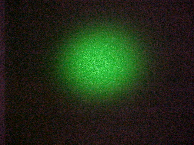
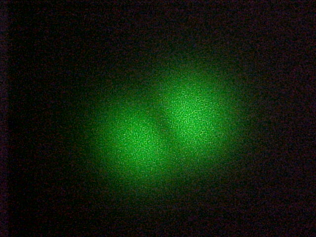
NA of a fiber is related to a certain wavelength. When I let green laser beam (wavelength is 532 nm) pass through the fiber, the laser beam coming out the fiber is no longer single-mode. By adjusting the angle of two mirrors we get different modes of the laser beam, as shown in the above pictures. The reason is that the wavelength of the green beam is so small that fiber can not restrict transmission to a single mode. As to the last picture, it seems still to be a Gaussian profile. The figure below is the result of the measurement. Using the 1% beam radius (measured with the larger detector) in the same way as before we get NA (1%) = sin(theta) = 0.147 This number is about 9% bigger than the NA = 0.135 measured with the red light. The Normalized Frequency Parameter (V number) is V = 2 * 3.14 * NA * a / wavelength = 2.80 if I use the specified NA value NA = 0.12 and it is V = 3.38 if I use my measured NA = 0.147. Either value is greater than 2.405, which explains why the fiber is multi-mode.
Acknowledgements I am very appreciated for Dr. John Noé's instruction and generous help in the experiment. I would like to thank Prof. Harold Metcalf for his much help. Many thanks to Doug Broege, Xueqing Liu and Xiyue Miao for helping me make the experimental set-ups. Back To Home
Numerical apertureof objective lens
If we put a " rainbow glasses" very near at the end of fiber. We can see an interesting phenomenon as shown above. And there is no such a phenomenon if the laser beam dose not pass through the fiber. This maybe because??? Acknowledgements I am very appreciated for Dr. John Noé's instruction and generous help in the experiment. I would like to thank Prof. Harold Metcalf for his much help. Many thanks to Doug Broege, Xueqing Liu and Xiyue Miao for helping me make the experimental set-ups. Back To Home
Step index single-mode fiber. * Supplier: Thorlabs * Catalog Number: P1-3224-FC-5 (arrived in March, 2001) * Operating wavelength: 630 nm * Length of the fiber: 5 m * Mode field diameter (MFD) 4.0 µm * Cladding diameter: 125 µm * NA: 0.12 * V parameter: 2.35 for 630 nm light Detector: The output of the laser beam out of the fiber is observed with a photo detector (Thorlabs DET-110) together with a multimeter and a resistor or R = 10 kohms. Sometimes a smaller detector of the same type was used (DET-210). Translation stage to move detector in small steps.
Experimental Set-up Apparatus description: Helium-Neon laser (Metrologic): Wavelength = 633 nm, power = 1 mw. Green laser pointer (Edmund Scientific): Wavelength = 532 nm, power = 1 mw. Two mirrors: mirror 1 is for x-y alignment, mirror 2 is for angular adjustment. Step index single-mode fiber. * Supplier: Thorlabs * Catalog Number: P1-3224-FC-5 (arrived in March, 2001) * Operating wavelength: 630 nm * Length of the fiber: 5 m * Mode field diameter (MFD) 4.0 µm * Cladding diameter: 125 µm * NA: 0.12 * V parameter: 2.35 for 630 nm light Detector: The output of the laser beam out of the fiber is observed with a photo detector (Thorlabs DET-110) together with a multimeter and a resistor or R = 10 kohms. Sometimes a smaller detector of the same type was used (DET-210). Translation stage to move detector in small steps. Measurement and Result First catch the laser beam into the fiber by adjusting the two mirrors. I used the way that Xueqing Liu describes on her webreport. Measure the NA of the fiber. NA = sin (theta = half-cone angle) We measure the width of the laser beam by measuring the Gauss profile of the beam coming out of the fiber. I fit the data to the formula y = y0 + A * exp { -2 (x-x0)2/w2 } using the program Origin 5.0. I get y0 = 50.9 mV, which is an offset due to the intensity of the light in the room; x0 = 41.2 mm, which is the center of the Gaussian profile; and width w = 26.4 mm. This means that a point 26.4 mm from the center of laser beam is the 1/e2 = 0.135 intensity point. I regard w = 26.4 mm as the radius of the spot size, and the distance between the end of the fiber and the front of the detector is L = 295 mm. So I get NA (1/e2) = sin(theta) = 0.089 This value is smaller than expected value, which should be 0.12. Why? But on the page 238 of the THORLABS catolog book, there is a sentence that says that NA for a similar type of fiber is measured at 1% power angle in the far field. At the 1% power angle, I get the radius of the laser beam is 40.1 mm. And the distance between end of the fiber and laser beam is 295 mm. So we get NA (1%) = sin(theta) = 0.135 This value is greater than expected value, which should be 0.12. Why? This may be caused by the detector. The detector is not a spot but a square with certain area, so it will expand the Gaussian profile outside. To prove this, we remeasure the profile by a detector with smaller area. The figure following is the Gaussian profile of laser beam which is measured with a small detector. In the same way as before we get L = 293 mm, w [1/e2] = 25.7 mm, w [1%] = 40.0 mm, and therefore NA (1%) = sin(theta) = 0.131 This value is a little less than 0.135 as expected, but it is still greater than 0.12. NA of a fiber is related to a certain wavelength. When I let green laser beam (wavelength is 532 nm) pass through the fiber, the laser beam coming out the fiber is no longer single-mode. By adjusting the angle of two mirrors we get different modes of the laser beam, as shown in the above pictures. The reason is that the wavelength of the green beam is so small that fiber can not restrict transmission to a single mode. As to the last picture, it seems still to be a Gaussian profile. The figure below is the result of the measurement. Using the 1% beam radius (measured with the larger detector) in the same way as before we get NA (1%) = sin(theta) = 0.147 This number is about 9% bigger than the NA = 0.135 measured with the red light. The Normalized Frequency Parameter (V number) is V = 2 * 3.14 * NA * a / wavelength = 2.80 if I use the specified NA value NA = 0.12 and it is V = 3.38 if I use my measured NA = 0.147. Either value is greater than 2.405, which explains why the fiber is multi-mode. Another Interesting Thing (Discovered by Doug Broege) If we put a " rainbow glasses" very near at the end of fiber. We can see an interesting phenomenon as shown above. And there is no such a phenomenon if the laser beam dose not pass through the fiber. This maybe because??? Acknowledgements I am very appreciated for Dr. John Noé's instruction and generous help in the experiment. I would like to thank Prof. Harold Metcalf for his much help. Many thanks to Doug Broege, Xueqing Liu and Xiyue Miao for helping me make the experimental set-ups. Back To Home
The purpose of my project is to study the properties of Numerical Aperture (NA) of the single-mode step-index fiber. The basic requirement for single mode fiber is that the core be small enough to restrict transmission to a single mode. Single mode fiber is optical fiber that is designed for the transmission of a single mode of light as a carrier and is used for long-distance signal transmission. The number of the modes allowed in a given fiber is determined by a relationship between the wavelength of the light passing through the fiber, the core diameter of the fiber, and the material of the fiber. This relationship is known as the Normalized Frequency Parameter, or V number. The mathematical description of the V number is V= 2 * (pi) * NA * a / lambda NA = Numerical Aperture(see below) a = fiber radius (microns) lambda = wavelength (microns) A single-mode fiber has a V number that is less than 2.405, for most optical wavelengths. It will propagate light in a single guided mode. A multi-mode fiber has a V number that is greater than 2.405, for most optical wavelength and therefore will propagate in many paths through the fiber. The numerical aperture (NA) is a measurement of the ability of an optical fiber to capture light. All fibers have acceptance angle. The sine of the half of the acceptance angle of a fiber is known as the NA. The NA of the fiber, and also the acceptance angle, is determined by the ratio of refractive indices of the optical fiber core and its cladding. Rays entering the a fiber at a angle greater than the NA will not be reflected internally. Experimental Set-up Apparatus description: Helium-Neon laser (Metrologic): Wavelength = 633 nm, power = 1 mw. Green laser pointer (Edmund Scientific): Wavelength = 532 nm, power = 1 mw. Two mirrors: mirror 1 is for x-y alignment, mirror 2 is for angular adjustment. Step index single-mode fiber. * Supplier: Thorlabs * Catalog Number: P1-3224-FC-5 (arrived in March, 2001) * Operating wavelength: 630 nm * Length of the fiber: 5 m * Mode field diameter (MFD) 4.0 µm * Cladding diameter: 125 µm * NA: 0.12 * V parameter: 2.35 for 630 nm light Detector: The output of the laser beam out of the fiber is observed with a photo detector (Thorlabs DET-110) together with a multimeter and a resistor or R = 10 kohms. Sometimes a smaller detector of the same type was used (DET-210). Translation stage to move detector in small steps. Measurement and Result First catch the laser beam into the fiber by adjusting the two mirrors. I used the way that Xueqing Liu describes on her webreport. Measure the NA of the fiber. NA = sin (theta = half-cone angle) We measure the width of the laser beam by measuring the Gauss profile of the beam coming out of the fiber. I fit the data to the formula y = y0 + A * exp { -2 (x-x0)2/w2 } using the program Origin 5.0. I get y0 = 50.9 mV, which is an offset due to the intensity of the light in the room; x0 = 41.2 mm, which is the center of the Gaussian profile; and width w = 26.4 mm. This means that a point 26.4 mm from the center of laser beam is the 1/e2 = 0.135 intensity point. I regard w = 26.4 mm as the radius of the spot size, and the distance between the end of the fiber and the front of the detector is L = 295 mm. So I get NA (1/e2) = sin(theta) = 0.089 This value is smaller than expected value, which should be 0.12. Why? But on the page 238 of the THORLABS catolog book, there is a sentence that says that NA for a similar type of fiber is measured at 1% power angle in the far field. At the 1% power angle, I get the radius of the laser beam is 40.1 mm. And the distance between end of the fiber and laser beam is 295 mm. So we get NA (1%) = sin(theta) = 0.135 This value is greater than expected value, which should be 0.12. Why? This may be caused by the detector. The detector is not a spot but a square with certain area, so it will expand the Gaussian profile outside. To prove this, we remeasure the profile by a detector with smaller area. The figure following is the Gaussian profile of laser beam which is measured with a small detector. In the same way as before we get L = 293 mm, w [1/e2] = 25.7 mm, w [1%] = 40.0 mm, and therefore NA (1%) = sin(theta) = 0.131 This value is a little less than 0.135 as expected, but it is still greater than 0.12. NA of a fiber is related to a certain wavelength. When I let green laser beam (wavelength is 532 nm) pass through the fiber, the laser beam coming out the fiber is no longer single-mode. By adjusting the angle of two mirrors we get different modes of the laser beam, as shown in the above pictures. The reason is that the wavelength of the green beam is so small that fiber can not restrict transmission to a single mode. As to the last picture, it seems still to be a Gaussian profile. The figure below is the result of the measurement. Using the 1% beam radius (measured with the larger detector) in the same way as before we get NA (1%) = sin(theta) = 0.147 This number is about 9% bigger than the NA = 0.135 measured with the red light. The Normalized Frequency Parameter (V number) is V = 2 * 3.14 * NA * a / wavelength = 2.80 if I use the specified NA value NA = 0.12 and it is V = 3.38 if I use my measured NA = 0.147. Either value is greater than 2.405, which explains why the fiber is multi-mode. Another Interesting Thing (Discovered by Doug Broege) If we put a " rainbow glasses" very near at the end of fiber. We can see an interesting phenomenon as shown above. And there is no such a phenomenon if the laser beam dose not pass through the fiber. This maybe because??? Acknowledgements I am very appreciated for Dr. John Noé's instruction and generous help in the experiment. I would like to thank Prof. Harold Metcalf for his much help. Many thanks to Doug Broege, Xueqing Liu and Xiyue Miao for helping me make the experimental set-ups. Back To Home
The core diameter of glass fiber is very small, hence it has higher technology requirements to couple light into the core region, such as light sources.
Measure the NA of the fiber. NA = sin (theta = half-cone angle) We measure the width of the laser beam by measuring the Gauss profile of the beam coming out of the fiber. I fit the data to the formula y = y0 + A * exp { -2 (x-x0)2/w2 } using the program Origin 5.0. I get y0 = 50.9 mV, which is an offset due to the intensity of the light in the room; x0 = 41.2 mm, which is the center of the Gaussian profile; and width w = 26.4 mm. This means that a point 26.4 mm from the center of laser beam is the 1/e2 = 0.135 intensity point. I regard w = 26.4 mm as the radius of the spot size, and the distance between the end of the fiber and the front of the detector is L = 295 mm. So I get NA (1/e2) = sin(theta) = 0.089 This value is smaller than expected value, which should be 0.12. Why? But on the page 238 of the THORLABS catolog book, there is a sentence that says that NA for a similar type of fiber is measured at 1% power angle in the far field. At the 1% power angle, I get the radius of the laser beam is 40.1 mm. And the distance between end of the fiber and laser beam is 295 mm. So we get NA (1%) = sin(theta) = 0.135 This value is greater than expected value, which should be 0.12. Why? This may be caused by the detector. The detector is not a spot but a square with certain area, so it will expand the Gaussian profile outside. To prove this, we remeasure the profile by a detector with smaller area. The figure following is the Gaussian profile of laser beam which is measured with a small detector. In the same way as before we get L = 293 mm, w [1/e2] = 25.7 mm, w [1%] = 40.0 mm, and therefore NA (1%) = sin(theta) = 0.131 This value is a little less than 0.135 as expected, but it is still greater than 0.12. NA of a fiber is related to a certain wavelength. When I let green laser beam (wavelength is 532 nm) pass through the fiber, the laser beam coming out the fiber is no longer single-mode. By adjusting the angle of two mirrors we get different modes of the laser beam, as shown in the above pictures. The reason is that the wavelength of the green beam is so small that fiber can not restrict transmission to a single mode. As to the last picture, it seems still to be a Gaussian profile. The figure below is the result of the measurement. Using the 1% beam radius (measured with the larger detector) in the same way as before we get NA (1%) = sin(theta) = 0.147 This number is about 9% bigger than the NA = 0.135 measured with the red light. The Normalized Frequency Parameter (V number) is V = 2 * 3.14 * NA * a / wavelength = 2.80 if I use the specified NA value NA = 0.12 and it is V = 3.38 if I use my measured NA = 0.147. Either value is greater than 2.405, which explains why the fiber is multi-mode.
The numerical aperture (NA) is a measurement of the ability of an optical fiber to capture light. All fibers have acceptance angle. The sine of the half of the acceptance angle of a fiber is known as the NA. The NA of the fiber, and also the acceptance angle, is determined by the ratio of refractive indices of the optical fiber core and its cladding. Rays entering the a fiber at a angle greater than the NA will not be reflected internally. Experimental Set-up Apparatus description: Helium-Neon laser (Metrologic): Wavelength = 633 nm, power = 1 mw. Green laser pointer (Edmund Scientific): Wavelength = 532 nm, power = 1 mw. Two mirrors: mirror 1 is for x-y alignment, mirror 2 is for angular adjustment. Step index single-mode fiber. * Supplier: Thorlabs * Catalog Number: P1-3224-FC-5 (arrived in March, 2001) * Operating wavelength: 630 nm * Length of the fiber: 5 m * Mode field diameter (MFD) 4.0 µm * Cladding diameter: 125 µm * NA: 0.12 * V parameter: 2.35 for 630 nm light Detector: The output of the laser beam out of the fiber is observed with a photo detector (Thorlabs DET-110) together with a multimeter and a resistor or R = 10 kohms. Sometimes a smaller detector of the same type was used (DET-210). Translation stage to move detector in small steps. Measurement and Result First catch the laser beam into the fiber by adjusting the two mirrors. I used the way that Xueqing Liu describes on her webreport. Measure the NA of the fiber. NA = sin (theta = half-cone angle) We measure the width of the laser beam by measuring the Gauss profile of the beam coming out of the fiber. I fit the data to the formula y = y0 + A * exp { -2 (x-x0)2/w2 } using the program Origin 5.0. I get y0 = 50.9 mV, which is an offset due to the intensity of the light in the room; x0 = 41.2 mm, which is the center of the Gaussian profile; and width w = 26.4 mm. This means that a point 26.4 mm from the center of laser beam is the 1/e2 = 0.135 intensity point. I regard w = 26.4 mm as the radius of the spot size, and the distance between the end of the fiber and the front of the detector is L = 295 mm. So I get NA (1/e2) = sin(theta) = 0.089 This value is smaller than expected value, which should be 0.12. Why? But on the page 238 of the THORLABS catolog book, there is a sentence that says that NA for a similar type of fiber is measured at 1% power angle in the far field. At the 1% power angle, I get the radius of the laser beam is 40.1 mm. And the distance between end of the fiber and laser beam is 295 mm. So we get NA (1%) = sin(theta) = 0.135 This value is greater than expected value, which should be 0.12. Why? This may be caused by the detector. The detector is not a spot but a square with certain area, so it will expand the Gaussian profile outside. To prove this, we remeasure the profile by a detector with smaller area. The figure following is the Gaussian profile of laser beam which is measured with a small detector. In the same way as before we get L = 293 mm, w [1/e2] = 25.7 mm, w [1%] = 40.0 mm, and therefore NA (1%) = sin(theta) = 0.131 This value is a little less than 0.135 as expected, but it is still greater than 0.12. NA of a fiber is related to a certain wavelength. When I let green laser beam (wavelength is 532 nm) pass through the fiber, the laser beam coming out the fiber is no longer single-mode. By adjusting the angle of two mirrors we get different modes of the laser beam, as shown in the above pictures. The reason is that the wavelength of the green beam is so small that fiber can not restrict transmission to a single mode. As to the last picture, it seems still to be a Gaussian profile. The figure below is the result of the measurement. Using the 1% beam radius (measured with the larger detector) in the same way as before we get NA (1%) = sin(theta) = 0.147 This number is about 9% bigger than the NA = 0.135 measured with the red light. The Normalized Frequency Parameter (V number) is V = 2 * 3.14 * NA * a / wavelength = 2.80 if I use the specified NA value NA = 0.12 and it is V = 3.38 if I use my measured NA = 0.147. Either value is greater than 2.405, which explains why the fiber is multi-mode. Another Interesting Thing (Discovered by Doug Broege) If we put a " rainbow glasses" very near at the end of fiber. We can see an interesting phenomenon as shown above. And there is no such a phenomenon if the laser beam dose not pass through the fiber. This maybe because??? Acknowledgements I am very appreciated for Dr. John Noé's instruction and generous help in the experiment. I would like to thank Prof. Harold Metcalf for his much help. Many thanks to Doug Broege, Xueqing Liu and Xiyue Miao for helping me make the experimental set-ups. Back To Home
Numerical apertureof optical fiber
The network using plastic optical fiber can be installed by untrained personnel. Even home users can handle and install these fibers.
Since glass cores are efficient at transmitting light and allow for significantly higher transfer speeds, glass optical fibers can be used over long sensing distances.
Numerical apertureunit
Helium-Neon laser (Metrologic): Wavelength = 633 nm, power = 1 mw. Green laser pointer (Edmund Scientific): Wavelength = 532 nm, power = 1 mw. Two mirrors: mirror 1 is for x-y alignment, mirror 2 is for angular adjustment. Step index single-mode fiber. * Supplier: Thorlabs * Catalog Number: P1-3224-FC-5 (arrived in March, 2001) * Operating wavelength: 630 nm * Length of the fiber: 5 m * Mode field diameter (MFD) 4.0 µm * Cladding diameter: 125 µm * NA: 0.12 * V parameter: 2.35 for 630 nm light Detector: The output of the laser beam out of the fiber is observed with a photo detector (Thorlabs DET-110) together with a multimeter and a resistor or R = 10 kohms. Sometimes a smaller detector of the same type was used (DET-210). Translation stage to move detector in small steps. Measurement and Result First catch the laser beam into the fiber by adjusting the two mirrors. I used the way that Xueqing Liu describes on her webreport. Measure the NA of the fiber. NA = sin (theta = half-cone angle) We measure the width of the laser beam by measuring the Gauss profile of the beam coming out of the fiber. I fit the data to the formula y = y0 + A * exp { -2 (x-x0)2/w2 } using the program Origin 5.0. I get y0 = 50.9 mV, which is an offset due to the intensity of the light in the room; x0 = 41.2 mm, which is the center of the Gaussian profile; and width w = 26.4 mm. This means that a point 26.4 mm from the center of laser beam is the 1/e2 = 0.135 intensity point. I regard w = 26.4 mm as the radius of the spot size, and the distance between the end of the fiber and the front of the detector is L = 295 mm. So I get NA (1/e2) = sin(theta) = 0.089 This value is smaller than expected value, which should be 0.12. Why? But on the page 238 of the THORLABS catolog book, there is a sentence that says that NA for a similar type of fiber is measured at 1% power angle in the far field. At the 1% power angle, I get the radius of the laser beam is 40.1 mm. And the distance between end of the fiber and laser beam is 295 mm. So we get NA (1%) = sin(theta) = 0.135 This value is greater than expected value, which should be 0.12. Why? This may be caused by the detector. The detector is not a spot but a square with certain area, so it will expand the Gaussian profile outside. To prove this, we remeasure the profile by a detector with smaller area. The figure following is the Gaussian profile of laser beam which is measured with a small detector. In the same way as before we get L = 293 mm, w [1/e2] = 25.7 mm, w [1%] = 40.0 mm, and therefore NA (1%) = sin(theta) = 0.131 This value is a little less than 0.135 as expected, but it is still greater than 0.12. NA of a fiber is related to a certain wavelength. When I let green laser beam (wavelength is 532 nm) pass through the fiber, the laser beam coming out the fiber is no longer single-mode. By adjusting the angle of two mirrors we get different modes of the laser beam, as shown in the above pictures. The reason is that the wavelength of the green beam is so small that fiber can not restrict transmission to a single mode. As to the last picture, it seems still to be a Gaussian profile. The figure below is the result of the measurement. Using the 1% beam radius (measured with the larger detector) in the same way as before we get NA (1%) = sin(theta) = 0.147 This number is about 9% bigger than the NA = 0.135 measured with the red light. The Normalized Frequency Parameter (V number) is V = 2 * 3.14 * NA * a / wavelength = 2.80 if I use the specified NA value NA = 0.12 and it is V = 3.38 if I use my measured NA = 0.147. Either value is greater than 2.405, which explains why the fiber is multi-mode. Another Interesting Thing (Discovered by Doug Broege) If we put a " rainbow glasses" very near at the end of fiber. We can see an interesting phenomenon as shown above. And there is no such a phenomenon if the laser beam dose not pass through the fiber. This maybe because??? Acknowledgements I am very appreciated for Dr. John Noé's instruction and generous help in the experiment. I would like to thank Prof. Harold Metcalf for his much help. Many thanks to Doug Broege, Xueqing Liu and Xiyue Miao for helping me make the experimental set-ups. Back To Home
Detector: The output of the laser beam out of the fiber is observed with a photo detector (Thorlabs DET-110) together with a multimeter and a resistor or R = 10 kohms. Sometimes a smaller detector of the same type was used (DET-210). Translation stage to move detector in small steps.
From the introduction of glass optical fiber and plastic optical fiber below, you may have a clearer impression of the difference between these two terms. The following comparison chart which summarizes the parameters will help you better understand it.
Numerical apertureof lens
NA = sin (theta = half-cone angle) We measure the width of the laser beam by measuring the Gauss profile of the beam coming out of the fiber. I fit the data to the formula y = y0 + A * exp { -2 (x-x0)2/w2 } using the program Origin 5.0. I get y0 = 50.9 mV, which is an offset due to the intensity of the light in the room; x0 = 41.2 mm, which is the center of the Gaussian profile; and width w = 26.4 mm. This means that a point 26.4 mm from the center of laser beam is the 1/e2 = 0.135 intensity point. I regard w = 26.4 mm as the radius of the spot size, and the distance between the end of the fiber and the front of the detector is L = 295 mm. So I get NA (1/e2) = sin(theta) = 0.089 This value is smaller than expected value, which should be 0.12. Why? But on the page 238 of the THORLABS catolog book, there is a sentence that says that NA for a similar type of fiber is measured at 1% power angle in the far field. At the 1% power angle, I get the radius of the laser beam is 40.1 mm. And the distance between end of the fiber and laser beam is 295 mm. So we get NA (1%) = sin(theta) = 0.135 This value is greater than expected value, which should be 0.12. Why? This may be caused by the detector. The detector is not a spot but a square with certain area, so it will expand the Gaussian profile outside. To prove this, we remeasure the profile by a detector with smaller area. The figure following is the Gaussian profile of laser beam which is measured with a small detector. In the same way as before we get L = 293 mm, w [1/e2] = 25.7 mm, w [1%] = 40.0 mm, and therefore NA (1%) = sin(theta) = 0.131 This value is a little less than 0.135 as expected, but it is still greater than 0.12. NA of a fiber is related to a certain wavelength. When I let green laser beam (wavelength is 532 nm) pass through the fiber, the laser beam coming out the fiber is no longer single-mode. By adjusting the angle of two mirrors we get different modes of the laser beam, as shown in the above pictures. The reason is that the wavelength of the green beam is so small that fiber can not restrict transmission to a single mode. As to the last picture, it seems still to be a Gaussian profile. The figure below is the result of the measurement. Using the 1% beam radius (measured with the larger detector) in the same way as before we get NA (1%) = sin(theta) = 0.147 This number is about 9% bigger than the NA = 0.135 measured with the red light. The Normalized Frequency Parameter (V number) is V = 2 * 3.14 * NA * a / wavelength = 2.80 if I use the specified NA value NA = 0.12 and it is V = 3.38 if I use my measured NA = 0.147. Either value is greater than 2.405, which explains why the fiber is multi-mode.
Two mirrors: mirror 1 is for x-y alignment, mirror 2 is for angular adjustment. Step index single-mode fiber. * Supplier: Thorlabs * Catalog Number: P1-3224-FC-5 (arrived in March, 2001) * Operating wavelength: 630 nm * Length of the fiber: 5 m * Mode field diameter (MFD) 4.0 µm * Cladding diameter: 125 µm * NA: 0.12 * V parameter: 2.35 for 630 nm light Detector: The output of the laser beam out of the fiber is observed with a photo detector (Thorlabs DET-110) together with a multimeter and a resistor or R = 10 kohms. Sometimes a smaller detector of the same type was used (DET-210). Translation stage to move detector in small steps.
Measurement and Result First catch the laser beam into the fiber by adjusting the two mirrors. I used the way that Xueqing Liu describes on her webreport. Measure the NA of the fiber. NA = sin (theta = half-cone angle) We measure the width of the laser beam by measuring the Gauss profile of the beam coming out of the fiber. I fit the data to the formula y = y0 + A * exp { -2 (x-x0)2/w2 } using the program Origin 5.0. I get y0 = 50.9 mV, which is an offset due to the intensity of the light in the room; x0 = 41.2 mm, which is the center of the Gaussian profile; and width w = 26.4 mm. This means that a point 26.4 mm from the center of laser beam is the 1/e2 = 0.135 intensity point. I regard w = 26.4 mm as the radius of the spot size, and the distance between the end of the fiber and the front of the detector is L = 295 mm. So I get NA (1/e2) = sin(theta) = 0.089 This value is smaller than expected value, which should be 0.12. Why? But on the page 238 of the THORLABS catolog book, there is a sentence that says that NA for a similar type of fiber is measured at 1% power angle in the far field. At the 1% power angle, I get the radius of the laser beam is 40.1 mm. And the distance between end of the fiber and laser beam is 295 mm. So we get NA (1%) = sin(theta) = 0.135 This value is greater than expected value, which should be 0.12. Why? This may be caused by the detector. The detector is not a spot but a square with certain area, so it will expand the Gaussian profile outside. To prove this, we remeasure the profile by a detector with smaller area. The figure following is the Gaussian profile of laser beam which is measured with a small detector. In the same way as before we get L = 293 mm, w [1/e2] = 25.7 mm, w [1%] = 40.0 mm, and therefore NA (1%) = sin(theta) = 0.131 This value is a little less than 0.135 as expected, but it is still greater than 0.12. NA of a fiber is related to a certain wavelength. When I let green laser beam (wavelength is 532 nm) pass through the fiber, the laser beam coming out the fiber is no longer single-mode. By adjusting the angle of two mirrors we get different modes of the laser beam, as shown in the above pictures. The reason is that the wavelength of the green beam is so small that fiber can not restrict transmission to a single mode. As to the last picture, it seems still to be a Gaussian profile. The figure below is the result of the measurement. Using the 1% beam radius (measured with the larger detector) in the same way as before we get NA (1%) = sin(theta) = 0.147 This number is about 9% bigger than the NA = 0.135 measured with the red light. The Normalized Frequency Parameter (V number) is V = 2 * 3.14 * NA * a / wavelength = 2.80 if I use the specified NA value NA = 0.12 and it is V = 3.38 if I use my measured NA = 0.147. Either value is greater than 2.405, which explains why the fiber is multi-mode. Another Interesting Thing (Discovered by Doug Broege) If we put a " rainbow glasses" very near at the end of fiber. We can see an interesting phenomenon as shown above. And there is no such a phenomenon if the laser beam dose not pass through the fiber. This maybe because??? Acknowledgements I am very appreciated for Dr. John Noé's instruction and generous help in the experiment. I would like to thank Prof. Harold Metcalf for his much help. Many thanks to Doug Broege, Xueqing Liu and Xiyue Miao for helping me make the experimental set-ups. Back To Home
Plastic optical fiber (POF) is introduced to optical links later than glass optical fiber. It is an optical fiber in which the core and cladding are both made out of plastic or polymeric materials rather than glass. It is typically made up of PMMA (acrylic), a general-purpose resin as the core material, thus it is also referred to as PMMA optical fiber. Similar to the glass optical fiber, POF transmits the light through the core of the fiber. POFs are usually multimode fibers with large core (diameter from 0.15-2 mm). Made from just one acrylic monofilament, plastic fiber optic cables are efficient when used with visible red status indicator light sources.
Green laser pointer (Edmund Scientific): Wavelength = 532 nm, power = 1 mw. Two mirrors: mirror 1 is for x-y alignment, mirror 2 is for angular adjustment. Step index single-mode fiber. * Supplier: Thorlabs * Catalog Number: P1-3224-FC-5 (arrived in March, 2001) * Operating wavelength: 630 nm * Length of the fiber: 5 m * Mode field diameter (MFD) 4.0 µm * Cladding diameter: 125 µm * NA: 0.12 * V parameter: 2.35 for 630 nm light Detector: The output of the laser beam out of the fiber is observed with a photo detector (Thorlabs DET-110) together with a multimeter and a resistor or R = 10 kohms. Sometimes a smaller detector of the same type was used (DET-210). Translation stage to move detector in small steps.
The installation of glass optical fibers requires highly trained technicians, and the tools and equipment for fiber termination are usually expensive.
Two mirrors: mirror 1 is for x-y alignment, mirror 2 is for angular adjustment. Step index single-mode fiber. * Supplier: Thorlabs * Catalog Number: P1-3224-FC-5 (arrived in March, 2001) * Operating wavelength: 630 nm * Length of the fiber: 5 m * Mode field diameter (MFD) 4.0 µm * Cladding diameter: 125 µm * NA: 0.12 * V parameter: 2.35 for 630 nm light Detector: The output of the laser beam out of the fiber is observed with a photo detector (Thorlabs DET-110) together with a multimeter and a resistor or R = 10 kohms. Sometimes a smaller detector of the same type was used (DET-210). Translation stage to move detector in small steps.
Numerical apertureformula
Glass optical fiber enables you to use a photoelectric sensor in areas where you wouldn’t normally be able to use them. With this advantage, you can choose sensors with a wide range of housings, mounting styles, and features for your specific application.
Apparatus description: Helium-Neon laser (Metrologic): Wavelength = 633 nm, power = 1 mw. Green laser pointer (Edmund Scientific): Wavelength = 532 nm, power = 1 mw. Two mirrors: mirror 1 is for x-y alignment, mirror 2 is for angular adjustment. Step index single-mode fiber. * Supplier: Thorlabs * Catalog Number: P1-3224-FC-5 (arrived in March, 2001) * Operating wavelength: 630 nm * Length of the fiber: 5 m * Mode field diameter (MFD) 4.0 µm * Cladding diameter: 125 µm * NA: 0.12 * V parameter: 2.35 for 630 nm light Detector: The output of the laser beam out of the fiber is observed with a photo detector (Thorlabs DET-110) together with a multimeter and a resistor or R = 10 kohms. Sometimes a smaller detector of the same type was used (DET-210). Translation stage to move detector in small steps. Measurement and Result First catch the laser beam into the fiber by adjusting the two mirrors. I used the way that Xueqing Liu describes on her webreport. Measure the NA of the fiber. NA = sin (theta = half-cone angle) We measure the width of the laser beam by measuring the Gauss profile of the beam coming out of the fiber. I fit the data to the formula y = y0 + A * exp { -2 (x-x0)2/w2 } using the program Origin 5.0. I get y0 = 50.9 mV, which is an offset due to the intensity of the light in the room; x0 = 41.2 mm, which is the center of the Gaussian profile; and width w = 26.4 mm. This means that a point 26.4 mm from the center of laser beam is the 1/e2 = 0.135 intensity point. I regard w = 26.4 mm as the radius of the spot size, and the distance between the end of the fiber and the front of the detector is L = 295 mm. So I get NA (1/e2) = sin(theta) = 0.089 This value is smaller than expected value, which should be 0.12. Why? But on the page 238 of the THORLABS catolog book, there is a sentence that says that NA for a similar type of fiber is measured at 1% power angle in the far field. At the 1% power angle, I get the radius of the laser beam is 40.1 mm. And the distance between end of the fiber and laser beam is 295 mm. So we get NA (1%) = sin(theta) = 0.135 This value is greater than expected value, which should be 0.12. Why? This may be caused by the detector. The detector is not a spot but a square with certain area, so it will expand the Gaussian profile outside. To prove this, we remeasure the profile by a detector with smaller area. The figure following is the Gaussian profile of laser beam which is measured with a small detector. In the same way as before we get L = 293 mm, w [1/e2] = 25.7 mm, w [1%] = 40.0 mm, and therefore NA (1%) = sin(theta) = 0.131 This value is a little less than 0.135 as expected, but it is still greater than 0.12. NA of a fiber is related to a certain wavelength. When I let green laser beam (wavelength is 532 nm) pass through the fiber, the laser beam coming out the fiber is no longer single-mode. By adjusting the angle of two mirrors we get different modes of the laser beam, as shown in the above pictures. The reason is that the wavelength of the green beam is so small that fiber can not restrict transmission to a single mode. As to the last picture, it seems still to be a Gaussian profile. The figure below is the result of the measurement. Using the 1% beam radius (measured with the larger detector) in the same way as before we get NA (1%) = sin(theta) = 0.147 This number is about 9% bigger than the NA = 0.135 measured with the red light. The Normalized Frequency Parameter (V number) is V = 2 * 3.14 * NA * a / wavelength = 2.80 if I use the specified NA value NA = 0.12 and it is V = 3.38 if I use my measured NA = 0.147. Either value is greater than 2.405, which explains why the fiber is multi-mode. Another Interesting Thing (Discovered by Doug Broege) If we put a " rainbow glasses" very near at the end of fiber. We can see an interesting phenomenon as shown above. And there is no such a phenomenon if the laser beam dose not pass through the fiber. This maybe because??? Acknowledgements I am very appreciated for Dr. John Noé's instruction and generous help in the experiment. I would like to thank Prof. Harold Metcalf for his much help. Many thanks to Doug Broege, Xueqing Liu and Xiyue Miao for helping me make the experimental set-ups. Back To Home
Glass fiber cables can be used in high-temperature applications like furnaces, ovens, and condensers in large engines, as well as in extremely low-temperature areas such as cold storage warehouses.
As transmission mediums, glass optical fiber and plastic optical fiber are both used for high-speed data transmission. However, they consist of different materials and have their own advantages and are suitable for different applications. When choosing the correct optical fiber for the application, you are recommended to take the factors listed above into account.
Numerical apertureof microscope
There is another type of optical fiber—plastic clad silica (PCS) fiber or sometimes called hard clad silica (HCS) fiber. It features a glass core and a plastic cladding but is used less than plastic optical fiber. Compared with all-glass fibers, it has significantly lower performance characteristics, providing higher loss and lower bandwidths. The main advantage is the big core (up to 200-300μm), which is advantageous in applications such as industrial and medical applications.
Acknowledgements I am very appreciated for Dr. John Noé's instruction and generous help in the experiment. I would like to thank Prof. Harold Metcalf for his much help. Many thanks to Doug Broege, Xueqing Liu and Xiyue Miao for helping me make the experimental set-ups. Back To Home
Plastic optical fibers use harmless green or red light that is easily visible towards the eye. They are safe when installed in a house without risk to inquisitive children.
NA of a fiber is related to a certain wavelength. When I let green laser beam (wavelength is 532 nm) pass through the fiber, the laser beam coming out the fiber is no longer single-mode. By adjusting the angle of two mirrors we get different modes of the laser beam, as shown in the above pictures. The reason is that the wavelength of the green beam is so small that fiber can not restrict transmission to a single mode. As to the last picture, it seems still to be a Gaussian profile. The figure below is the result of the measurement. Using the 1% beam radius (measured with the larger detector) in the same way as before we get NA (1%) = sin(theta) = 0.147 This number is about 9% bigger than the NA = 0.135 measured with the red light. The Normalized Frequency Parameter (V number) is V = 2 * 3.14 * NA * a / wavelength = 2.80 if I use the specified NA value NA = 0.12 and it is V = 3.38 if I use my measured NA = 0.147. Either value is greater than 2.405, which explains why the fiber is multi-mode.
The number of the modes allowed in a given fiber is determined by a relationship between the wavelength of the light passing through the fiber, the core diameter of the fiber, and the material of the fiber. This relationship is known as the Normalized Frequency Parameter, or V number. The mathematical description of the V number is V= 2 * (pi) * NA * a / lambda NA = Numerical Aperture(see below) a = fiber radius (microns) lambda = wavelength (microns) A single-mode fiber has a V number that is less than 2.405, for most optical wavelengths. It will propagate light in a single guided mode. A multi-mode fiber has a V number that is greater than 2.405, for most optical wavelength and therefore will propagate in many paths through the fiber. The numerical aperture (NA) is a measurement of the ability of an optical fiber to capture light. All fibers have acceptance angle. The sine of the half of the acceptance angle of a fiber is known as the NA. The NA of the fiber, and also the acceptance angle, is determined by the ratio of refractive indices of the optical fiber core and its cladding. Rays entering the a fiber at a angle greater than the NA will not be reflected internally. Experimental Set-up Apparatus description: Helium-Neon laser (Metrologic): Wavelength = 633 nm, power = 1 mw. Green laser pointer (Edmund Scientific): Wavelength = 532 nm, power = 1 mw. Two mirrors: mirror 1 is for x-y alignment, mirror 2 is for angular adjustment. Step index single-mode fiber. * Supplier: Thorlabs * Catalog Number: P1-3224-FC-5 (arrived in March, 2001) * Operating wavelength: 630 nm * Length of the fiber: 5 m * Mode field diameter (MFD) 4.0 µm * Cladding diameter: 125 µm * NA: 0.12 * V parameter: 2.35 for 630 nm light Detector: The output of the laser beam out of the fiber is observed with a photo detector (Thorlabs DET-110) together with a multimeter and a resistor or R = 10 kohms. Sometimes a smaller detector of the same type was used (DET-210). Translation stage to move detector in small steps. Measurement and Result First catch the laser beam into the fiber by adjusting the two mirrors. I used the way that Xueqing Liu describes on her webreport. Measure the NA of the fiber. NA = sin (theta = half-cone angle) We measure the width of the laser beam by measuring the Gauss profile of the beam coming out of the fiber. I fit the data to the formula y = y0 + A * exp { -2 (x-x0)2/w2 } using the program Origin 5.0. I get y0 = 50.9 mV, which is an offset due to the intensity of the light in the room; x0 = 41.2 mm, which is the center of the Gaussian profile; and width w = 26.4 mm. This means that a point 26.4 mm from the center of laser beam is the 1/e2 = 0.135 intensity point. I regard w = 26.4 mm as the radius of the spot size, and the distance between the end of the fiber and the front of the detector is L = 295 mm. So I get NA (1/e2) = sin(theta) = 0.089 This value is smaller than expected value, which should be 0.12. Why? But on the page 238 of the THORLABS catolog book, there is a sentence that says that NA for a similar type of fiber is measured at 1% power angle in the far field. At the 1% power angle, I get the radius of the laser beam is 40.1 mm. And the distance between end of the fiber and laser beam is 295 mm. So we get NA (1%) = sin(theta) = 0.135 This value is greater than expected value, which should be 0.12. Why? This may be caused by the detector. The detector is not a spot but a square with certain area, so it will expand the Gaussian profile outside. To prove this, we remeasure the profile by a detector with smaller area. The figure following is the Gaussian profile of laser beam which is measured with a small detector. In the same way as before we get L = 293 mm, w [1/e2] = 25.7 mm, w [1%] = 40.0 mm, and therefore NA (1%) = sin(theta) = 0.131 This value is a little less than 0.135 as expected, but it is still greater than 0.12. NA of a fiber is related to a certain wavelength. When I let green laser beam (wavelength is 532 nm) pass through the fiber, the laser beam coming out the fiber is no longer single-mode. By adjusting the angle of two mirrors we get different modes of the laser beam, as shown in the above pictures. The reason is that the wavelength of the green beam is so small that fiber can not restrict transmission to a single mode. As to the last picture, it seems still to be a Gaussian profile. The figure below is the result of the measurement. Using the 1% beam radius (measured with the larger detector) in the same way as before we get NA (1%) = sin(theta) = 0.147 This number is about 9% bigger than the NA = 0.135 measured with the red light. The Normalized Frequency Parameter (V number) is V = 2 * 3.14 * NA * a / wavelength = 2.80 if I use the specified NA value NA = 0.12 and it is V = 3.38 if I use my measured NA = 0.147. Either value is greater than 2.405, which explains why the fiber is multi-mode. Another Interesting Thing (Discovered by Doug Broege) If we put a " rainbow glasses" very near at the end of fiber. We can see an interesting phenomenon as shown above. And there is no such a phenomenon if the laser beam dose not pass through the fiber. This maybe because??? Acknowledgements I am very appreciated for Dr. John Noé's instruction and generous help in the experiment. I would like to thank Prof. Harold Metcalf for his much help. Many thanks to Doug Broege, Xueqing Liu and Xiyue Miao for helping me make the experimental set-ups. Back To Home
I fit the data to the formula y = y0 + A * exp { -2 (x-x0)2/w2 } using the program Origin 5.0. I get y0 = 50.9 mV, which is an offset due to the intensity of the light in the room; x0 = 41.2 mm, which is the center of the Gaussian profile; and width w = 26.4 mm. This means that a point 26.4 mm from the center of laser beam is the 1/e2 = 0.135 intensity point. I regard w = 26.4 mm as the radius of the spot size, and the distance between the end of the fiber and the front of the detector is L = 295 mm. So I get NA (1/e2) = sin(theta) = 0.089 This value is smaller than expected value, which should be 0.12. Why? But on the page 238 of the THORLABS catolog book, there is a sentence that says that NA for a similar type of fiber is measured at 1% power angle in the far field. At the 1% power angle, I get the radius of the laser beam is 40.1 mm. And the distance between end of the fiber and laser beam is 295 mm. So we get NA (1%) = sin(theta) = 0.135 This value is greater than expected value, which should be 0.12. Why? This may be caused by the detector. The detector is not a spot but a square with certain area, so it will expand the Gaussian profile outside. To prove this, we remeasure the profile by a detector with smaller area. The figure following is the Gaussian profile of laser beam which is measured with a small detector. In the same way as before we get L = 293 mm, w [1/e2] = 25.7 mm, w [1%] = 40.0 mm, and therefore NA (1%) = sin(theta) = 0.131 This value is a little less than 0.135 as expected, but it is still greater than 0.12. NA of a fiber is related to a certain wavelength. When I let green laser beam (wavelength is 532 nm) pass through the fiber, the laser beam coming out the fiber is no longer single-mode. By adjusting the angle of two mirrors we get different modes of the laser beam, as shown in the above pictures. The reason is that the wavelength of the green beam is so small that fiber can not restrict transmission to a single mode. As to the last picture, it seems still to be a Gaussian profile. The figure below is the result of the measurement. Using the 1% beam radius (measured with the larger detector) in the same way as before we get NA (1%) = sin(theta) = 0.147 This number is about 9% bigger than the NA = 0.135 measured with the red light. The Normalized Frequency Parameter (V number) is V = 2 * 3.14 * NA * a / wavelength = 2.80 if I use the specified NA value NA = 0.12 and it is V = 3.38 if I use my measured NA = 0.147. Either value is greater than 2.405, which explains why the fiber is multi-mode.
Introduction The purpose of my project is to study the properties of Numerical Aperture (NA) of the single-mode step-index fiber. The basic requirement for single mode fiber is that the core be small enough to restrict transmission to a single mode. Single mode fiber is optical fiber that is designed for the transmission of a single mode of light as a carrier and is used for long-distance signal transmission. The number of the modes allowed in a given fiber is determined by a relationship between the wavelength of the light passing through the fiber, the core diameter of the fiber, and the material of the fiber. This relationship is known as the Normalized Frequency Parameter, or V number. The mathematical description of the V number is V= 2 * (pi) * NA * a / lambda NA = Numerical Aperture(see below) a = fiber radius (microns) lambda = wavelength (microns) A single-mode fiber has a V number that is less than 2.405, for most optical wavelengths. It will propagate light in a single guided mode. A multi-mode fiber has a V number that is greater than 2.405, for most optical wavelength and therefore will propagate in many paths through the fiber. The numerical aperture (NA) is a measurement of the ability of an optical fiber to capture light. All fibers have acceptance angle. The sine of the half of the acceptance angle of a fiber is known as the NA. The NA of the fiber, and also the acceptance angle, is determined by the ratio of refractive indices of the optical fiber core and its cladding. Rays entering the a fiber at a angle greater than the NA will not be reflected internally. Experimental Set-up Apparatus description: Helium-Neon laser (Metrologic): Wavelength = 633 nm, power = 1 mw. Green laser pointer (Edmund Scientific): Wavelength = 532 nm, power = 1 mw. Two mirrors: mirror 1 is for x-y alignment, mirror 2 is for angular adjustment. Step index single-mode fiber. * Supplier: Thorlabs * Catalog Number: P1-3224-FC-5 (arrived in March, 2001) * Operating wavelength: 630 nm * Length of the fiber: 5 m * Mode field diameter (MFD) 4.0 µm * Cladding diameter: 125 µm * NA: 0.12 * V parameter: 2.35 for 630 nm light Detector: The output of the laser beam out of the fiber is observed with a photo detector (Thorlabs DET-110) together with a multimeter and a resistor or R = 10 kohms. Sometimes a smaller detector of the same type was used (DET-210). Translation stage to move detector in small steps. Measurement and Result First catch the laser beam into the fiber by adjusting the two mirrors. I used the way that Xueqing Liu describes on her webreport. Measure the NA of the fiber. NA = sin (theta = half-cone angle) We measure the width of the laser beam by measuring the Gauss profile of the beam coming out of the fiber. I fit the data to the formula y = y0 + A * exp { -2 (x-x0)2/w2 } using the program Origin 5.0. I get y0 = 50.9 mV, which is an offset due to the intensity of the light in the room; x0 = 41.2 mm, which is the center of the Gaussian profile; and width w = 26.4 mm. This means that a point 26.4 mm from the center of laser beam is the 1/e2 = 0.135 intensity point. I regard w = 26.4 mm as the radius of the spot size, and the distance between the end of the fiber and the front of the detector is L = 295 mm. So I get NA (1/e2) = sin(theta) = 0.089 This value is smaller than expected value, which should be 0.12. Why? But on the page 238 of the THORLABS catolog book, there is a sentence that says that NA for a similar type of fiber is measured at 1% power angle in the far field. At the 1% power angle, I get the radius of the laser beam is 40.1 mm. And the distance between end of the fiber and laser beam is 295 mm. So we get NA (1%) = sin(theta) = 0.135 This value is greater than expected value, which should be 0.12. Why? This may be caused by the detector. The detector is not a spot but a square with certain area, so it will expand the Gaussian profile outside. To prove this, we remeasure the profile by a detector with smaller area. The figure following is the Gaussian profile of laser beam which is measured with a small detector. In the same way as before we get L = 293 mm, w [1/e2] = 25.7 mm, w [1%] = 40.0 mm, and therefore NA (1%) = sin(theta) = 0.131 This value is a little less than 0.135 as expected, but it is still greater than 0.12. NA of a fiber is related to a certain wavelength. When I let green laser beam (wavelength is 532 nm) pass through the fiber, the laser beam coming out the fiber is no longer single-mode. By adjusting the angle of two mirrors we get different modes of the laser beam, as shown in the above pictures. The reason is that the wavelength of the green beam is so small that fiber can not restrict transmission to a single mode. As to the last picture, it seems still to be a Gaussian profile. The figure below is the result of the measurement. Using the 1% beam radius (measured with the larger detector) in the same way as before we get NA (1%) = sin(theta) = 0.147 This number is about 9% bigger than the NA = 0.135 measured with the red light. The Normalized Frequency Parameter (V number) is V = 2 * 3.14 * NA * a / wavelength = 2.80 if I use the specified NA value NA = 0.12 and it is V = 3.38 if I use my measured NA = 0.147. Either value is greater than 2.405, which explains why the fiber is multi-mode. Another Interesting Thing (Discovered by Doug Broege) If we put a " rainbow glasses" very near at the end of fiber. We can see an interesting phenomenon as shown above. And there is no such a phenomenon if the laser beam dose not pass through the fiber. This maybe because??? Acknowledgements I am very appreciated for Dr. John Noé's instruction and generous help in the experiment. I would like to thank Prof. Harold Metcalf for his much help. Many thanks to Doug Broege, Xueqing Liu and Xiyue Miao for helping me make the experimental set-ups. Back To Home
Another Interesting Thing (Discovered by Doug Broege) If we put a " rainbow glasses" very near at the end of fiber. We can see an interesting phenomenon as shown above. And there is no such a phenomenon if the laser beam dose not pass through the fiber. This maybe because??? Acknowledgements I am very appreciated for Dr. John Noé's instruction and generous help in the experiment. I would like to thank Prof. Harold Metcalf for his much help. Many thanks to Doug Broege, Xueqing Liu and Xiyue Miao for helping me make the experimental set-ups. Back To Home
But on the page 238 of the THORLABS catolog book, there is a sentence that says that NA for a similar type of fiber is measured at 1% power angle in the far field. At the 1% power angle, I get the radius of the laser beam is 40.1 mm. And the distance between end of the fiber and laser beam is 295 mm. So we get NA (1%) = sin(theta) = 0.135 This value is greater than expected value, which should be 0.12. Why? This may be caused by the detector. The detector is not a spot but a square with certain area, so it will expand the Gaussian profile outside. To prove this, we remeasure the profile by a detector with smaller area. The figure following is the Gaussian profile of laser beam which is measured with a small detector. In the same way as before we get L = 293 mm, w [1/e2] = 25.7 mm, w [1%] = 40.0 mm, and therefore NA (1%) = sin(theta) = 0.131 This value is a little less than 0.135 as expected, but it is still greater than 0.12. NA of a fiber is related to a certain wavelength. When I let green laser beam (wavelength is 532 nm) pass through the fiber, the laser beam coming out the fiber is no longer single-mode. By adjusting the angle of two mirrors we get different modes of the laser beam, as shown in the above pictures. The reason is that the wavelength of the green beam is so small that fiber can not restrict transmission to a single mode. As to the last picture, it seems still to be a Gaussian profile. The figure below is the result of the measurement. Using the 1% beam radius (measured with the larger detector) in the same way as before we get NA (1%) = sin(theta) = 0.147 This number is about 9% bigger than the NA = 0.135 measured with the red light. The Normalized Frequency Parameter (V number) is V = 2 * 3.14 * NA * a / wavelength = 2.80 if I use the specified NA value NA = 0.12 and it is V = 3.38 if I use my measured NA = 0.147. Either value is greater than 2.405, which explains why the fiber is multi-mode.
We measure the width of the laser beam by measuring the Gauss profile of the beam coming out of the fiber. I fit the data to the formula y = y0 + A * exp { -2 (x-x0)2/w2 } using the program Origin 5.0. I get y0 = 50.9 mV, which is an offset due to the intensity of the light in the room; x0 = 41.2 mm, which is the center of the Gaussian profile; and width w = 26.4 mm. This means that a point 26.4 mm from the center of laser beam is the 1/e2 = 0.135 intensity point. I regard w = 26.4 mm as the radius of the spot size, and the distance between the end of the fiber and the front of the detector is L = 295 mm. So I get NA (1/e2) = sin(theta) = 0.089 This value is smaller than expected value, which should be 0.12. Why? But on the page 238 of the THORLABS catolog book, there is a sentence that says that NA for a similar type of fiber is measured at 1% power angle in the far field. At the 1% power angle, I get the radius of the laser beam is 40.1 mm. And the distance between end of the fiber and laser beam is 295 mm. So we get NA (1%) = sin(theta) = 0.135 This value is greater than expected value, which should be 0.12. Why? This may be caused by the detector. The detector is not a spot but a square with certain area, so it will expand the Gaussian profile outside. To prove this, we remeasure the profile by a detector with smaller area. The figure following is the Gaussian profile of laser beam which is measured with a small detector. In the same way as before we get L = 293 mm, w [1/e2] = 25.7 mm, w [1%] = 40.0 mm, and therefore NA (1%) = sin(theta) = 0.131 This value is a little less than 0.135 as expected, but it is still greater than 0.12. NA of a fiber is related to a certain wavelength. When I let green laser beam (wavelength is 532 nm) pass through the fiber, the laser beam coming out the fiber is no longer single-mode. By adjusting the angle of two mirrors we get different modes of the laser beam, as shown in the above pictures. The reason is that the wavelength of the green beam is so small that fiber can not restrict transmission to a single mode. As to the last picture, it seems still to be a Gaussian profile. The figure below is the result of the measurement. Using the 1% beam radius (measured with the larger detector) in the same way as before we get NA (1%) = sin(theta) = 0.147 This number is about 9% bigger than the NA = 0.135 measured with the red light. The Normalized Frequency Parameter (V number) is V = 2 * 3.14 * NA * a / wavelength = 2.80 if I use the specified NA value NA = 0.12 and it is V = 3.38 if I use my measured NA = 0.147. Either value is greater than 2.405, which explains why the fiber is multi-mode.
By adjusting the angle of two mirrors we get different modes of the laser beam, as shown in the above pictures. The reason is that the wavelength of the green beam is so small that fiber can not restrict transmission to a single mode. As to the last picture, it seems still to be a Gaussian profile. The figure below is the result of the measurement. Using the 1% beam radius (measured with the larger detector) in the same way as before we get NA (1%) = sin(theta) = 0.147 This number is about 9% bigger than the NA = 0.135 measured with the red light. The Normalized Frequency Parameter (V number) is V = 2 * 3.14 * NA * a / wavelength = 2.80 if I use the specified NA value NA = 0.12 and it is V = 3.38 if I use my measured NA = 0.147. Either value is greater than 2.405, which explains why the fiber is multi-mode.
I regard w = 26.4 mm as the radius of the spot size, and the distance between the end of the fiber and the front of the detector is L = 295 mm. So I get NA (1/e2) = sin(theta) = 0.089 This value is smaller than expected value, which should be 0.12. Why? But on the page 238 of the THORLABS catolog book, there is a sentence that says that NA for a similar type of fiber is measured at 1% power angle in the far field. At the 1% power angle, I get the radius of the laser beam is 40.1 mm. And the distance between end of the fiber and laser beam is 295 mm. So we get NA (1%) = sin(theta) = 0.135 This value is greater than expected value, which should be 0.12. Why? This may be caused by the detector. The detector is not a spot but a square with certain area, so it will expand the Gaussian profile outside. To prove this, we remeasure the profile by a detector with smaller area. The figure following is the Gaussian profile of laser beam which is measured with a small detector. In the same way as before we get L = 293 mm, w [1/e2] = 25.7 mm, w [1%] = 40.0 mm, and therefore NA (1%) = sin(theta) = 0.131 This value is a little less than 0.135 as expected, but it is still greater than 0.12. NA of a fiber is related to a certain wavelength. When I let green laser beam (wavelength is 532 nm) pass through the fiber, the laser beam coming out the fiber is no longer single-mode. By adjusting the angle of two mirrors we get different modes of the laser beam, as shown in the above pictures. The reason is that the wavelength of the green beam is so small that fiber can not restrict transmission to a single mode. As to the last picture, it seems still to be a Gaussian profile. The figure below is the result of the measurement. Using the 1% beam radius (measured with the larger detector) in the same way as before we get NA (1%) = sin(theta) = 0.147 This number is about 9% bigger than the NA = 0.135 measured with the red light. The Normalized Frequency Parameter (V number) is V = 2 * 3.14 * NA * a / wavelength = 2.80 if I use the specified NA value NA = 0.12 and it is V = 3.38 if I use my measured NA = 0.147. Either value is greater than 2.405, which explains why the fiber is multi-mode.
A multi-mode fiber has a V number that is greater than 2.405, for most optical wavelength and therefore will propagate in many paths through the fiber. The numerical aperture (NA) is a measurement of the ability of an optical fiber to capture light. All fibers have acceptance angle. The sine of the half of the acceptance angle of a fiber is known as the NA. The NA of the fiber, and also the acceptance angle, is determined by the ratio of refractive indices of the optical fiber core and its cladding. Rays entering the a fiber at a angle greater than the NA will not be reflected internally. Experimental Set-up Apparatus description: Helium-Neon laser (Metrologic): Wavelength = 633 nm, power = 1 mw. Green laser pointer (Edmund Scientific): Wavelength = 532 nm, power = 1 mw. Two mirrors: mirror 1 is for x-y alignment, mirror 2 is for angular adjustment. Step index single-mode fiber. * Supplier: Thorlabs * Catalog Number: P1-3224-FC-5 (arrived in March, 2001) * Operating wavelength: 630 nm * Length of the fiber: 5 m * Mode field diameter (MFD) 4.0 µm * Cladding diameter: 125 µm * NA: 0.12 * V parameter: 2.35 for 630 nm light Detector: The output of the laser beam out of the fiber is observed with a photo detector (Thorlabs DET-110) together with a multimeter and a resistor or R = 10 kohms. Sometimes a smaller detector of the same type was used (DET-210). Translation stage to move detector in small steps. Measurement and Result First catch the laser beam into the fiber by adjusting the two mirrors. I used the way that Xueqing Liu describes on her webreport. Measure the NA of the fiber. NA = sin (theta = half-cone angle) We measure the width of the laser beam by measuring the Gauss profile of the beam coming out of the fiber. I fit the data to the formula y = y0 + A * exp { -2 (x-x0)2/w2 } using the program Origin 5.0. I get y0 = 50.9 mV, which is an offset due to the intensity of the light in the room; x0 = 41.2 mm, which is the center of the Gaussian profile; and width w = 26.4 mm. This means that a point 26.4 mm from the center of laser beam is the 1/e2 = 0.135 intensity point. I regard w = 26.4 mm as the radius of the spot size, and the distance between the end of the fiber and the front of the detector is L = 295 mm. So I get NA (1/e2) = sin(theta) = 0.089 This value is smaller than expected value, which should be 0.12. Why? But on the page 238 of the THORLABS catolog book, there is a sentence that says that NA for a similar type of fiber is measured at 1% power angle in the far field. At the 1% power angle, I get the radius of the laser beam is 40.1 mm. And the distance between end of the fiber and laser beam is 295 mm. So we get NA (1%) = sin(theta) = 0.135 This value is greater than expected value, which should be 0.12. Why? This may be caused by the detector. The detector is not a spot but a square with certain area, so it will expand the Gaussian profile outside. To prove this, we remeasure the profile by a detector with smaller area. The figure following is the Gaussian profile of laser beam which is measured with a small detector. In the same way as before we get L = 293 mm, w [1/e2] = 25.7 mm, w [1%] = 40.0 mm, and therefore NA (1%) = sin(theta) = 0.131 This value is a little less than 0.135 as expected, but it is still greater than 0.12. NA of a fiber is related to a certain wavelength. When I let green laser beam (wavelength is 532 nm) pass through the fiber, the laser beam coming out the fiber is no longer single-mode. By adjusting the angle of two mirrors we get different modes of the laser beam, as shown in the above pictures. The reason is that the wavelength of the green beam is so small that fiber can not restrict transmission to a single mode. As to the last picture, it seems still to be a Gaussian profile. The figure below is the result of the measurement. Using the 1% beam radius (measured with the larger detector) in the same way as before we get NA (1%) = sin(theta) = 0.147 This number is about 9% bigger than the NA = 0.135 measured with the red light. The Normalized Frequency Parameter (V number) is V = 2 * 3.14 * NA * a / wavelength = 2.80 if I use the specified NA value NA = 0.12 and it is V = 3.38 if I use my measured NA = 0.147. Either value is greater than 2.405, which explains why the fiber is multi-mode. Another Interesting Thing (Discovered by Doug Broege) If we put a " rainbow glasses" very near at the end of fiber. We can see an interesting phenomenon as shown above. And there is no such a phenomenon if the laser beam dose not pass through the fiber. This maybe because??? Acknowledgements I am very appreciated for Dr. John Noé's instruction and generous help in the experiment. I would like to thank Prof. Harold Metcalf for his much help. Many thanks to Doug Broege, Xueqing Liu and Xiyue Miao for helping me make the experimental set-ups. Back To Home
Numerical aperture nacalculator
First catch the laser beam into the fiber by adjusting the two mirrors. I used the way that Xueqing Liu describes on her webreport. Measure the NA of the fiber. NA = sin (theta = half-cone angle) We measure the width of the laser beam by measuring the Gauss profile of the beam coming out of the fiber. I fit the data to the formula y = y0 + A * exp { -2 (x-x0)2/w2 } using the program Origin 5.0. I get y0 = 50.9 mV, which is an offset due to the intensity of the light in the room; x0 = 41.2 mm, which is the center of the Gaussian profile; and width w = 26.4 mm. This means that a point 26.4 mm from the center of laser beam is the 1/e2 = 0.135 intensity point. I regard w = 26.4 mm as the radius of the spot size, and the distance between the end of the fiber and the front of the detector is L = 295 mm. So I get NA (1/e2) = sin(theta) = 0.089 This value is smaller than expected value, which should be 0.12. Why? But on the page 238 of the THORLABS catolog book, there is a sentence that says that NA for a similar type of fiber is measured at 1% power angle in the far field. At the 1% power angle, I get the radius of the laser beam is 40.1 mm. And the distance between end of the fiber and laser beam is 295 mm. So we get NA (1%) = sin(theta) = 0.135 This value is greater than expected value, which should be 0.12. Why? This may be caused by the detector. The detector is not a spot but a square with certain area, so it will expand the Gaussian profile outside. To prove this, we remeasure the profile by a detector with smaller area. The figure following is the Gaussian profile of laser beam which is measured with a small detector. In the same way as before we get L = 293 mm, w [1/e2] = 25.7 mm, w [1%] = 40.0 mm, and therefore NA (1%) = sin(theta) = 0.131 This value is a little less than 0.135 as expected, but it is still greater than 0.12. NA of a fiber is related to a certain wavelength. When I let green laser beam (wavelength is 532 nm) pass through the fiber, the laser beam coming out the fiber is no longer single-mode. By adjusting the angle of two mirrors we get different modes of the laser beam, as shown in the above pictures. The reason is that the wavelength of the green beam is so small that fiber can not restrict transmission to a single mode. As to the last picture, it seems still to be a Gaussian profile. The figure below is the result of the measurement. Using the 1% beam radius (measured with the larger detector) in the same way as before we get NA (1%) = sin(theta) = 0.147 This number is about 9% bigger than the NA = 0.135 measured with the red light. The Normalized Frequency Parameter (V number) is V = 2 * 3.14 * NA * a / wavelength = 2.80 if I use the specified NA value NA = 0.12 and it is V = 3.38 if I use my measured NA = 0.147. Either value is greater than 2.405, which explains why the fiber is multi-mode.
This may be caused by the detector. The detector is not a spot but a square with certain area, so it will expand the Gaussian profile outside. To prove this, we remeasure the profile by a detector with smaller area. The figure following is the Gaussian profile of laser beam which is measured with a small detector.
Glass optical fibers are constructed of tiny strands of glass that are bundled together inside an application-specific sheathing like stainless steel for durability and high temperatures. They are attached to certain photoelectric sensors and guide light from the sensing head to the target. Glass optical fibers have an impressive temperature range, as low as -40°F and up to +900°F. The main applications for glass fiber are communication, sensor, and measurement system. Some types of glass optical fiber cables can also be used in harsh environments such as corrosive and wet environments.
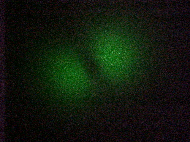
Experimental Set-up Apparatus description: Helium-Neon laser (Metrologic): Wavelength = 633 nm, power = 1 mw. Green laser pointer (Edmund Scientific): Wavelength = 532 nm, power = 1 mw. Two mirrors: mirror 1 is for x-y alignment, mirror 2 is for angular adjustment. Step index single-mode fiber. * Supplier: Thorlabs * Catalog Number: P1-3224-FC-5 (arrived in March, 2001) * Operating wavelength: 630 nm * Length of the fiber: 5 m * Mode field diameter (MFD) 4.0 µm * Cladding diameter: 125 µm * NA: 0.12 * V parameter: 2.35 for 630 nm light Detector: The output of the laser beam out of the fiber is observed with a photo detector (Thorlabs DET-110) together with a multimeter and a resistor or R = 10 kohms. Sometimes a smaller detector of the same type was used (DET-210). Translation stage to move detector in small steps. Measurement and Result First catch the laser beam into the fiber by adjusting the two mirrors. I used the way that Xueqing Liu describes on her webreport. Measure the NA of the fiber. NA = sin (theta = half-cone angle) We measure the width of the laser beam by measuring the Gauss profile of the beam coming out of the fiber. I fit the data to the formula y = y0 + A * exp { -2 (x-x0)2/w2 } using the program Origin 5.0. I get y0 = 50.9 mV, which is an offset due to the intensity of the light in the room; x0 = 41.2 mm, which is the center of the Gaussian profile; and width w = 26.4 mm. This means that a point 26.4 mm from the center of laser beam is the 1/e2 = 0.135 intensity point. I regard w = 26.4 mm as the radius of the spot size, and the distance between the end of the fiber and the front of the detector is L = 295 mm. So I get NA (1/e2) = sin(theta) = 0.089 This value is smaller than expected value, which should be 0.12. Why? But on the page 238 of the THORLABS catolog book, there is a sentence that says that NA for a similar type of fiber is measured at 1% power angle in the far field. At the 1% power angle, I get the radius of the laser beam is 40.1 mm. And the distance between end of the fiber and laser beam is 295 mm. So we get NA (1%) = sin(theta) = 0.135 This value is greater than expected value, which should be 0.12. Why? This may be caused by the detector. The detector is not a spot but a square with certain area, so it will expand the Gaussian profile outside. To prove this, we remeasure the profile by a detector with smaller area. The figure following is the Gaussian profile of laser beam which is measured with a small detector. In the same way as before we get L = 293 mm, w [1/e2] = 25.7 mm, w [1%] = 40.0 mm, and therefore NA (1%) = sin(theta) = 0.131 This value is a little less than 0.135 as expected, but it is still greater than 0.12. NA of a fiber is related to a certain wavelength. When I let green laser beam (wavelength is 532 nm) pass through the fiber, the laser beam coming out the fiber is no longer single-mode. By adjusting the angle of two mirrors we get different modes of the laser beam, as shown in the above pictures. The reason is that the wavelength of the green beam is so small that fiber can not restrict transmission to a single mode. As to the last picture, it seems still to be a Gaussian profile. The figure below is the result of the measurement. Using the 1% beam radius (measured with the larger detector) in the same way as before we get NA (1%) = sin(theta) = 0.147 This number is about 9% bigger than the NA = 0.135 measured with the red light. The Normalized Frequency Parameter (V number) is V = 2 * 3.14 * NA * a / wavelength = 2.80 if I use the specified NA value NA = 0.12 and it is V = 3.38 if I use my measured NA = 0.147. Either value is greater than 2.405, which explains why the fiber is multi-mode. Another Interesting Thing (Discovered by Doug Broege) If we put a " rainbow glasses" very near at the end of fiber. We can see an interesting phenomenon as shown above. And there is no such a phenomenon if the laser beam dose not pass through the fiber. This maybe because??? Acknowledgements I am very appreciated for Dr. John Noé's instruction and generous help in the experiment. I would like to thank Prof. Harold Metcalf for his much help. Many thanks to Doug Broege, Xueqing Liu and Xiyue Miao for helping me make the experimental set-ups. Back To Home
For short-range connectivity and those who are lack of professional knowledge of glass fiber, POF is a better choice. For a challenging environment and higher transmission rate over a long distance, glass optical fiber should be considered.
Acknowledgements I am very appreciated for Dr. John Noé's instruction and generous help in the experiment. I would like to thank Prof. Harold Metcalf for his much help. Many thanks to Doug Broege, Xueqing Liu and Xiyue Miao for helping me make the experimental set-ups. Back To Home


 Ms.Cici
 8618319014500