
Stetson University – Edmunds Center Renovation - S3 Design - edmunds center
where λ λ is the wavelength of the light (or other electromagnetic radiation) and D is the diameter of the aperture, lens, mirror, etc., with which the two objects are observed. In the expression above, θ θ has units of radians.
The ocular lens, located at the top of a standard microscope and close to the sensor (receiving eye) receives the real image from the ocular lens, magnifies the image received and relays a virtual image to the sensor. While most eyepieces magnify 10x, there are some which provide no magnification and others which magnify as much as 30x. The magnification power of the microscope can be calculated by multiplying the magnification power of the eyepiece, or ocular lens, by the magnification power of the objective lens. For example, an objective lens with a magnification of 10x used in combination with a standard eyepiece (magnification 10x) would project an image of the specimen magnified 100x.
Function ofstagein microscope
Many objectives are designed to be used with a cover glass. Using an incorrect coverslip thickness can greatly reduce the optical performance of a microscopy system.
High powerobjective microscope function
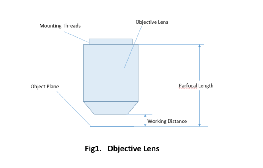
For keeping the objective at the proper position, there are mounting threads on almost all objectives. Commonly used mounting threads include RMS, M25 x 0.75, M26X 0.706, M32 x 0.75.
Two major lens components—the objective lens and the ocular lens, or eyepiece—work together to project the image of the specimen onto a sensor. This may be the human eye or a digital sensor, depending on the microscope setup.
A monochromatic laser beam of green light with a wavelength of 550 nm passes from air to water. The refractive index of water is 1.33. What will be the wavelength of the light after it enters the water?
The diameter of the beam is the same as if it were coming through an aperture of that size, so D = 1.00 mm. You are given λ λ, and you must solve for θ θ.
The ocular lens, or eyepiece, is also an optical assembly rather than a single lens, but it is typically more simple than the objective. Often it is composed of two lenses: a field lens and an eye lens. The design of the ocular lens determines the field of view of the microscope, as well as contributing to the total magnification of the system.
The conversion factor for radians to degrees is 1.000 radian = 57.3°. The spread is very small and would not be noticeable over short distances. The angle represents the angular separation of the central maximum and the first minimum.
Stage clipsmicroscope function
Each microscope objective is itself a complex assembly of lenses, and besides contributing to the magnification, it is the objective lens which determines the resolution power of the microscope. An objective lens can also provide optical aberration corrections. A reflective objective, for instance, includes two mirrors within the assembly. These mirrors can focus laser light as well as provide chromatic corrections.
High powerobjective lens
An interesting thing happens if you pass light through a large number of evenly-spaced parallel slits. Such an arrangement of slits is called a diffraction grating. An interference pattern is created that is very similar to the one formed by double-slit diffraction (see Figure 17.8 and Figure 17.10). A diffraction grating can be manufactured by scratching glass with a sharp tool to form a number of precisely positioned parallel lines, which act like slits. Diffraction gratings work both for transmission of light, as in Figure 17.15, and for reflection of light, as on the butterfly wings or the Australian opal shown in Figure 17.16, or the CD pictured in the opening illustration of this chapter. In addition to their use as novelty items, diffraction gratings are commonly used for spectroscopic dispersion and analysis of light. What makes them particularly useful is the fact that they form a sharper pattern than do double slits. That is, their bright regions are narrower and brighter, while their dark regions are darker. Figure 17.17 shows idealized graphs demonstrating the sharper pattern. Natural diffraction gratings occur in the feathers of certain birds. Tiny, fingerlike structures in regular patterns act as reflection gratings, producing constructive interference that gives the feathers colors not solely due to their pigmentation. The effect is called iridescence.
If you were completely transparent, it would be hard to recognize you from your photograph. The same problem arises when using a traditional microscope to view or photograph small transparent objects such as cells and microbes. Microscopes using differential interference contrast (DIC) solve the problem by making it possible to view microscopic objects with enhanced contrast, as shown in Figure 17.19.
This animation allows you to examine the workings of a laser. First view the picture of a real laser. Change the energy of the incoming photons, and see if you can match it to an excitation level that will produce pairs of coherent photons. Change the excitation level and try to match it to the incoming photon energy.
Diffraction gratings are used in spectroscopes to separate a light source into its component wavelengths. When a material is heated to incandescence, it gives off wavelengths of light characteristic of the chemical makeup of the material. A pure substance will produce a spectrum that is unique, thus allowing identification of the substance. Spectroscopes are also used to measure wavelengths both shorter and longer than visible light. Such instruments have become especially useful to astronomers and chemists. Figure 17.20 shows a diagram of a spectroscope.
A simple magnifier (magnifying glass), works when the object to be examined is situated within focal length of the magnifier lens, enabling larger virtual image is produced. This type of magnifier is very limited in both resolution and magnification. A compound microscope, on the other hand, uses a relay lens system instead of the single lens, and since each lens component can contribute magnifying power, the result is greatly increased capability.
where d is the distance between slits in the grating, λ λ is the wavelength of the light, and m is the order of the maximum. Note that this is exactly the same equation as for two slits separated by d. However, the slits are usually closer in diffraction gratings than in double slits, producing fewer maxima at larger angles.
Most objectives are designed to image specimens with air as the medium between the objective and the cover glass. However, for achieving higher working numerical apertures, some objectives are designed to image the specimen through another medium such as special oil with a refractive index of 1.51.
Objective lensmagnification
Laser beams are directional, very intense, and narrow (only about 0.5 mm in diameter). These properties lead to a number of applications in industry and medicine. The following are just a few examples:
At Shanghai Optics, we design and manufacture custom objectives and imaging systems to support our customers’ needs in many industries, including medical, biomedical, machine version, scientific research, and metrology, etc. Taking the client’s budget and precision requirements into consideration, our experienced engineering team ensure that each design can be manufactured at a reasonable cost and the optical performance is being met based on fabrication, assembly, and alignment tolerance analysis.
Figure 17.21 (a) shows the effect of passing light through a small circular aperture. Instead of a bright spot with sharp edges, a spot with a fuzzy edge surrounded by circles of light is obtained. This pattern is caused by diffraction similar to that produced by a single slit. Light from different parts of the circular aperture interferes constructively and destructively. The effect is most noticeable when the aperture is small, but the effect is there for large apertures, too.
Rearrange the equation for constructive interference conditions for a diffraction grating, and substitute the known values.
The grooves are actually one continuous groove that spirals outward from the center. Data are recorded in the grooves as binary code (zeroes and ones) in small pits. Information in the pits is detected by a laser that tracks along the groove. It gets even more complicated: The speed of rotation must be varied as the laser tracks toward the circumference so that the linear speed along the groove remains constant. There is also an error correction mechanism to prevent the laser beam from getting off track. A diffraction grating is used to create the first two maxima on either side of the track. If those maxima are not the same distance from the track, an error is indicated and then corrected.
Microscope Objectives or Objective lenses are in many ways the heart of the microscope, and are typically mounted on a rotating nosepiece or turret to enable easy selection. Many microscopes will be equipped with a scanning objective (4x), a low power objective (10x), a high power objective (40x), and perhaps even an oil immersion objective lens.
You are given enough information to calculate d, and you are given the values of λ λ and m. You will have to find the arcsin of a number to find θ θ.
A DIC microscope separates a polarized light source into two beams polarized at right angles to each other and coherent with each other, that is, in phase. After passing through the sample, the beams are recombined and realigned so they have the same plane of polarization. They then create an interference pattern caused by the differences in their optical path and the refractive indices of the parts of the sample they passed through. The result is an image with contrast and shadowing that could not be observed with traditional optics.
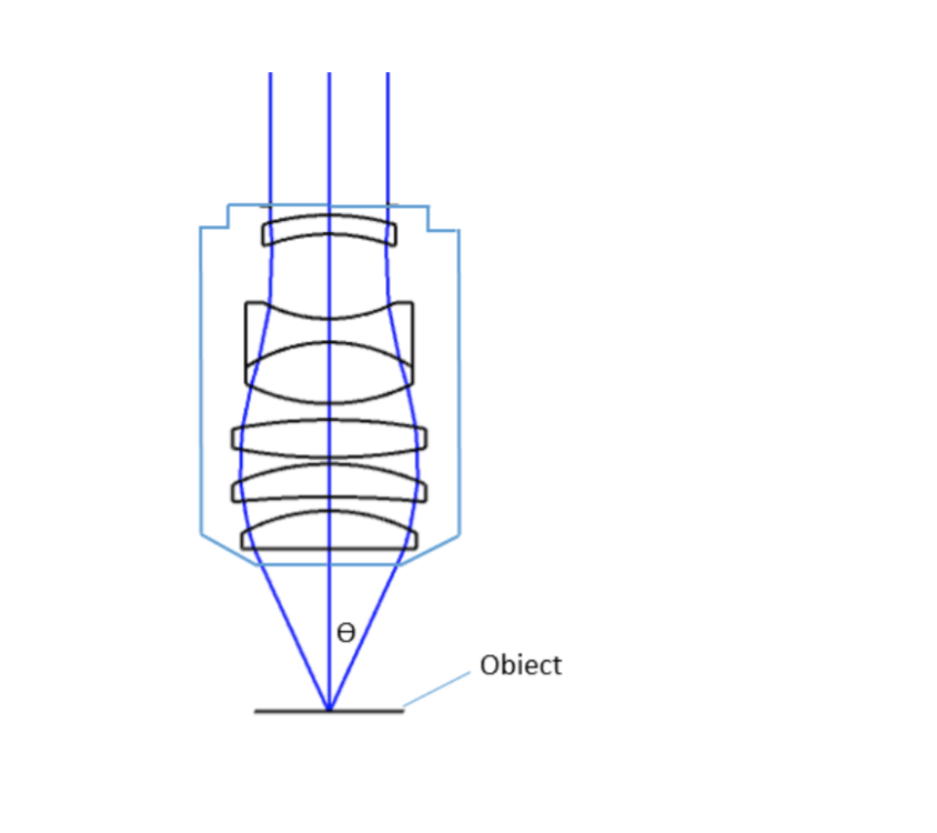
where θ is the maximum 1/2 acceptance ray angle of the objective, and n is the index of refraction of the immersion medium. Figure 2 shows the ray angle θ of an infinity-corrected objective.
You can assume that the refractive index of air is the same as that of light in a vacuum because they are so close. You then have all the information you need to solve for λ n λ n .
The pits are reflective because they have been coated with a thin layer of aluminum. That allows the laser beam to be reflected back and directed toward a photodiode detector. The signal can then be processed and converted to the audio we hear.
Light diffracts as it moves through space, bending around obstacles and interfering constructively and destructively. While diffraction allows light to be used as a spectroscopic tool, it also limits the detail we can obtain in images.
Objective lenses can be classified based on the objective construction, field of use, microscopy method, performance (optical aberration corrections), and magnification. Many microscope objective manufacturers offer a wide range of objective designs, which provide various degrees of optical aberration corrections for supporting different needs. Mirrors or reflective elements are used in objective lenses for the applications that requires chromatic aberration over board spectral ranges. Most traditional microscopy systems use refractive objectives such as achromatic objectives (the cheaper objectives) for laboratory microscope applications and plan apochromats (expensive objectives) for biological and science research microscope applications.
The refractive index of air is 1.0003, so the approximation holds for three significant figures. You would not see the light change color, however. Color is determined by frequency, not wavelength.
Magnification is one important parameter. Magnification is usually denoted by an X next to a numeric value. Objectives are available in a range of magnifications from 2X to 200X.
Can you see the grooves on a CD or DVD (see Figure 17.18)? You may think you can because you know they are there, but they are extremely narrow—1,600 in a millimeter. Because the width of the grooves is similar to wavelengths of visible light, they form a diffraction grating. That is why you see rainbows on a CD. The colors are attractive, but they are incidental to the functions of storing and retrieving audio and other data.
The parfocal length is the distance between the objective mounting plane and the specimen / object. This is another specification that can often vary by manufacturer.
Typesof objectivelenses
A microscope objective is an important component of a microscopy or imaging system for a range of science research, biological, industrial, and general lab applications.. An objective lens determines the basic performance of an optical microscope or imaging systems and is designed for various performance needs and applications. It is located closest to the object and is an important component in imaging an object onto the human eye or an image sensor.
Since the objective is closest to the specimen being examined, it will relay a real image to the ocular lens. While doing so, it contributes a base magnification of anywhere from 4x (for a scanning objective lens, typically used to provide an overview of a sample) to 100x (for oil immersion objectives).
shows how to the wavelength in a given medium, λ n λ n , is related to the wavelength in a vacuum, λ λ, and the refractive index, n, of the medium. The equation is useful for calculating the change in wavelength of a monochromatic laser beam in various media. The analysis of a diffraction grating is very similar to that for a double slit. As you know from the discussion of double slits in Young’s double-slit experiment, light is diffracted by, and spreads out after passing through, each slit. Rays travel at an angle θ θ relative to the incident direction. Each ray travels a different distance to a common point on a screen far away. The rays start in phase, and they can be in or out of phase when they reach a screen, depending on the difference in the path lengths traveled. Each ray travels a distance that differs by dsinθ dsinθ from that of its neighbor, where d is the distance between slits. If dsinθ dsinθ equals an integral number of wavelengths, the rays all arrive in phase, and constructive interference (a maximum) is obtained. Thus, the condition necessary to obtain constructive interference for a diffraction grating is
There are many situations in which diffraction limits the resolution. The acuity of vision is limited because light passes through the pupil, the circular aperture of the eye. Be aware that the diffraction-like spreading of light is due to the limited diameter of a light beam, not the interaction with an aperture. Thus light passing through a lens with a diameter of D shows the diffraction effect and spreads, blurring the image, just as light passing through an aperture of diameter D does. Diffraction limits the resolution of any system having a lens or mirror. Telescopes are also limited by diffraction, because of the finite diameter, D, of their primary mirror.
dsinθ = mλ θ = sin −1 mλ d = sin −1 ( (1)(520) 5,000 ) = 5.97 dsinθ = mλ θ = sin −1 mλ d = sin −1 ( (1)(520) 5,000 ) = 5.97
The optical aberration correction determines the optical performance of an objective lens and plays a central role in the image quality and measurement accuracy of imaging or microscopy systems. According to the degrees of the aberration corrections, objective lenses are generally classified into five basic types: Achromat, Plan Achromat, Plan Fluorite (Plan Semi-Apochromat), Plan Apochromat, and Super Apochromat.
Alpha Industrial Park, Tu Thon Village, Ly Thuong Kiet Commune, Yen My District, Hung Yen Province Vietnam 17721 +84 221-730-8668 rfqvn@shanghai-optics.com
While the simplest of microscopes is simply a magnifying glass with a single lens, compound microscopes used today are highly complex devices with a carefully designed series of lenses, filters, polarizers, beamsplitters, sensors, and perhaps even illumination sources. The exact combination of optical components used will depend on the application of the microscope; the wavelength of light with which it is intended to be used, and the resolution and magnification required in the final image.
Just what is the resolution limit of an aperture or lens? To answer that question, consider the diffraction pattern for a circular aperture, which, similar to the diffraction pattern of light passing through a slit, has a central maximum that is wider and brighter than the maxima surrounding it (see Figure 17.21 (a)). It can be shown that, for a circular aperture of diameter D, the first minimum in the diffraction pattern occurs at θ=1.22λ/D θ=1.22λ/D, provided that the aperture is large compared with the wavelength of light, which is the case for most optical instruments. The accepted criterion for determining the diffraction limit to resolution based on diffraction was developed by Lord Rayleigh in the 19th century. The Rayleigh criterion for the diffraction limit to resolution states that two images are just resolvable when the center of the diffraction pattern of one is directly over the first minimum of the diffraction pattern of the other. See Figure 17.22 (b). The first minimum is at an angle of θ=1.22λ/D θ=1.22λ/D, so that two point objects are just resolvable if they are separated by the angle
Objectives are complex multi-element lenses. For any given application, careful consideration of the optical parameters and specifications is necessary. In many cases, custom-designed objective assemblies provide the best-fit solution for meeting all the requirements of a specialized application. Custom parameters may include antireflection coatings, chromatic focus shift, working distance, image quality (MTF and spot size), lens mount, glass window thickness, and field of view, among others.
In 1917, Albert Einstein was thinking about photons and excited atoms. He considered an atom excited by a certain amount of energy and what would happen if that atom were hit by a photon with the same amount of energy. He suggested that the atom would emit a photon with that amount of energy, and it would be accompanied by the original photon. The exciting part is that you would have two photons with the same energy and they would be in phase. Those photons could go on to hit other excited atoms, and soon you would have a stream of in-phase photons. Such a light stream is said to be coherent. Some four decades later, Einstein’s idea found application in a process called, light amplification by stimulated emission of radiation. Take the first letters of all the words (except by and “of”) and write them in order. You get the word laser (see Figure 17.2 (a)), which is the name of the device that produces such a beam of light.
What is the angle between two just-resolved points of light for a 3.00 mm diameter pupil, assuming an average wavelength of 550 nm?
Where are diffraction gratings used? Diffraction gratings are key components of monochromators—devices that separate the various wavelengths of incoming light and allow a beam with only a specific wavelength to pass through. Monochromators are used, for example, in optical imaging of particular wavelengths from biological or medical samples. A diffraction grating can be chosen to specifically analyze a wavelength of light emitted by molecules in diseased cells in a biopsy sample, or to help excite strategic molecules in the sample with a selected frequency of light. Another important use is in optical fiber technologies where fibers are designed to provide optimum performance at specific wavelengths. A range of diffraction gratings is available for selecting specific wavelengths for such use.
Room 609, 6/F, Global Gateway Tower, No.63 Wing Hong Street, Cheung Sha Wan, Kowloon, Hong Kong +852-54993705 info@shanghai-optics.com
What isobjective lens in microscope
Early in the chapter, it was mentioned that when light passes from one medium to another, its speed and wavelength change, but its frequency remains constant. The equation
This angle seems reasonable for the first maximum. Recall that the meaning of sin‒1 (or arcsin) is the angle with a sine that is (the unknown). Remember that the value of sinθ sinθ will not be greater than 1 for any value of θ θ.
Field of View is the area of the object that can be imaged by a microscopy system. The size of the field of view is determined by the objective magnification or focal length of the tube lens for an infinite-corrected objective. In a camera system, the field of view of the objective is related to the sensor size.
A diffraction grating has 2000 lines per centimeter. At what angle will the first-order maximum form for green light with a wavelength of 520 nm?
Since indirect backlight illumination is generally more effective than direct illumination, most microscopes do not include an internal light source. Instead, they rely on daylight or on background illumination such as a lightbulb. In brightfield illumination, also known as Koehler illumination, two convex lenses saturate the specimen with external light admitted from behind. These two lenses, the collector lens and condenser lens, work together to provide a bright, even, and constant light throughout the system: on the image plane as well as on the object plane. This system of illumination is used in many compound microscopes, including student microscopes and those found in many research labs.
Function ofcondenserin microscope
A microscope is a special optical device designed to magnify the image of an object. Depending on the type of microscope, it may project the image either onto a human eye or onto a recording or video device. As an example, consider the photographs of cells that can be found in a science textbook. These photographs have all been taken by a specialized microscope, and may be called micrographs.
A beam of yellow light has a wavelength of 600 nm in a vacuum and a wavelength of 397 nm in Plexiglas. What is the refractive index of Plexiglas?
How does diffraction affect the detail that can be observed when light passes through an aperture? Figure 17.21 (b) shows the diffraction pattern produced by two point light sources that are close to one another. The pattern is similar to that for a single point source, and it is just barely possible to tell that there are two light sources rather than one. If they are closer together, as in Figure 17.21 (c), you cannot distinguish them, thus limiting the detail, or resolution, you can obtain. That limit is an inescapable consequence of the wave nature of light.
Important specifications are marked on the barrel of the objective, so students or researchers can easily identify the properties of an objective and determine the optical performance and working conditions for proper use. Figure 1 shows a diagram of an objective lens. A detailed discussion of the objection specifications is provided below.


 Ms.Cici
 8618319014500