
Seeview Security: Home - see vision camera
Objective lensmagnification
[latex]m_{\text{e}}=-\frac{d_{\text{i}}\prime}{d_{\text{o}}\prime}=-\frac{-367\text{ mm}}{44.0\text{ mm}}=8.33\\[/latex].
Calculate the magnification of an object placed 6.20 mm from a compound microscope that has a 6.00 mm focal length objective and a 50.0 mm focal length eyepiece. The objective and eyepiece are separated by 23.0 cm.
Single vision lenses with an aspheric design are available for correcting nearsightedness, farsightedness, and astigmatism, and progressive lenses for presbyopia, bifocals, and trifocals. It is possible to purchase aspheric lenses in regular plastic, although most are made from high index materials.
DIAMOND AR (anti reflective coating) has similar spectral properties to the DIAMOX + coating, is available on polycarbonate, acrylic and glass substrates.
compound microscope: a microscope constructed from two convex lenses, the first serving as the ocular lens(close to the eye) and the second serving as the objective lens
Scanningobjective lens
Compressed Air Dusters at Office Depot & OfficeMax. Shop today online, in store or buy online and pick up in stores.
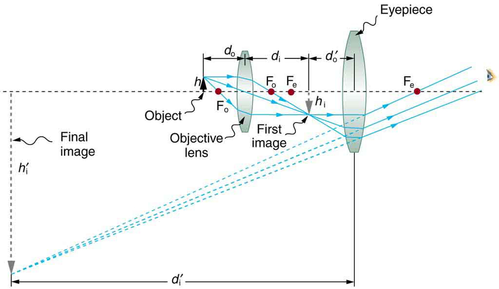
Figure 2. A compound microscope composed of two lenses, an objective and an eyepiece. The objective forms a case 1 image that is larger than the object. This first image is the object for the eyepiece. The eyepiece forms a case 2 final image that is further magnified.
It is true that the complicated curves used in aspheric lenses make them more expensive than conventional lenses; however, these thinner, lighter lenses provide exceptional cosmetic and visual benefits that make them a worthwhile investment.
JA Strother · 2021 · 10 — Optical systems with integrated tunable lenses allow for rapid axial-scanning without mechanical translation of the components. However, ...
Can the NA be larger than 1.00? The answer is ‘yes’ if we use immersion lenses in which a medium such as oil, glycerine or water is placed between the objective and the microscope cover slip. This minimizes the mismatch in refractive indices as light rays go through different media, generally providing a greater light-gathering ability and an increase in resolution. Figure 5 shows light rays when using air and immersion lenses.
Figure 6. Illumination of a specimen in a microscope. (a) Transmitted light from a condenser lens. (b) Transmitted light from a mirror condenser. (c) Dark field illumination by scattering (the illuminating beam misses the objective lens). (d) High magnification illumination with reflected light – normally laser light.
Solution : A convex lens acts as a magnifying glass, when it forms a virtual, erect and magnified image of an object. For this, the object is to be placed ...
Objective lens microscopefunction
Unlike a baseball, conventional lenses have a spherical front surface, which means that its curve extends across its entire surface.
A minus lens’ spherical design does not provide the same slimming effect as a positive lens, but it does significantly reduce edge thickness in comparison with conventional lenses.
5. (a) +18.3 cm (on the eyepiece side of the objective lens); (b) −60.0; (c) −11.3 cm (on the objective side of the eyepiece); (d) +6.67; (e) −400
Lenses with aspheric surfaces, on the other hand, are characterized by a complex front surface that gradually changes in curvature from the center to the edge of the lens.
While the numerical aperture can be used to compare resolutions of various objectives, it does not indicate how far the lens could be from the specimen. This is specified by the “working distance,” which is the distance (in mm usually) from the front lens element of the objective to the specimen, or cover glass. The higher the NA the closer the lens will be to the specimen and the more chances there are of breaking the cover slip and damaging both the specimen and the lens. The focal length of an objective lens is different than the working distance. This is because objective lenses are made of a combination of lenses and the focal length is measured from inside the barrel. The working distance is a parameter that microscopists can use more readily as it is measured from the outermost lens. The working distance decreases as the NA and magnification both increase.
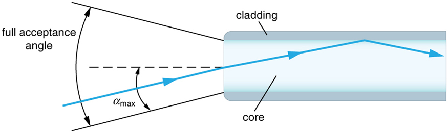
As the f-number decreases, the camera is able to gather light from a larger angle, giving wide-angle photography. As usual there is a trade-off. A greater f/# means less light reaches the image plane. A setting of f/16 usually allows one to take pictures in bright sunlight as the aperture diameter is small. In optical fibers, light needs to be focused into the fiber. Figure 4 shows the angle used in calculating the NA of an optical fiber.
Microscopes were first developed in the early 1600s by eyeglass makers in The Netherlands and Denmark. The simplest compound microscope is constructed from two convex lenses as shown schematically in Figure 2. The first lens is called the objective lens, and has typical magnification values from 5× to 100×. In standard microscopes, the objectives are mounted such that when you switch between objectives, the sample remains in focus. Objectives arranged in this way are described as parfocal. The second, the eyepiece, also referred to as the ocular, has several lenses which slide inside a cylindrical barrel. The focusing ability is provided by the movement of both the objective lens and the eyepiece. The purpose of a microscope is to magnify small objects, and both lenses contribute to the final magnification. Additionally, the final enlarged image is produced in a location far enough from the observer to be easily viewed, since the eye cannot focus on objects or images that are too close.
Figure 7. An electron microscope has the capability to image individual atoms on a material. The microscope uses vacuum technology, sophisticated detectors and state of the art image processing software. (credit: Dave Pape)
Using spherical plus lenses results in slightly flatter curves, so that the lens does not bulge into the frame. This gives the eyewear a slimmer, more pleasing appearance.
The aspheric lens design is thinner, lighter, and has a slimmer profile than ordinary lenses, regardless of whether you are nearsighted or farsighted.
[latex]\displaystyle\frac{1}{d_{\text{i}}\prime}=\frac{1}{f_{\text{e}}}-\frac{1}{d_{\text{o}}\prime}=\frac{1}{50.0\text{ mm}}-\frac{1}{44.0\text{ mm}}=\frac{0.00273}{\text{mm}}\\[/latex]
where do and di are the object and image distances, respectively, for the objective lens as labeled in Figure 2. The object distance is given to be do=6.20 mm, but the image distance di is not known. Isolating di, we have
As a result, those with strong prescriptions will be able to wear a greater selection of frames without having to worry about their lenses being too thick.
When using a microscope we do not see the entire extent of the sample. Depending on the eyepiece and objective lens we see a restricted region which we say is the field of view. The objective is then manipulated in two-dimensions above the sample to view other regions of the sample. Electronic scanning of either the objective or the sample is used in scanning microscopy. The image formed at each point during the scanning is combined using a computer to generate an image of a larger region of the sample at a selected magnification.
Due to their flatter design and position slightly closer to the face than traditional lenses, aspheric lenses may cause increased reflections from the front and back surfaces. It is therefore highly recommended that all aspheric lenses be treated with an anti-reflective coating.
Figure 5. Light rays from a specimen entering the objective. Paths for immersion medium of air (a), water (b) (n = 1.33), and oil (c) (n = 1.51) are shown. The water and oil immersions allow more rays to enter the objective, increasing the resolution.
Normal optical microscopes can magnify up to 1500× with a theoretical resolution of −0.2 μm. The lenses can be quite complicated and are composed of multiple elements to reduce aberrations. Microscope objective lenses are particularly important as they primarily gather light from the specimen. Three parameters describe microscope objectives: the numerical aperture (NA), the magnification (m), and the working distance. The NA is related to the light gathering ability of a lens and is obtained using the angle of acceptance θ formed by the maximum cone of rays focusing on the specimen (see Figure 3a) and is given by NA = n sin α, where n is the refractive index of the medium between the lens and the specimen and [latex]\alpha=\frac{\theta}{2}\\[/latex]. As the angle of acceptance given by θ increases, NA becomes larger and more light is gathered from a smaller focal region giving higher resolution. A 0.75 NA objective gives more detail than a 0.10 NA objective.
It is important to choose the right frame when using aspheric lenses for several reasons. The best-looking eyewear results when the frame is not overly large and the eyes are centered in the middle. Selecting the correct frame to complement your new aspheric lenses will be assisted by your eye doctor or optician.
High powerobjective microscopefunction
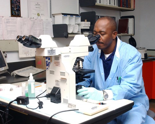
Although the eye is marvelous in its ability to see objects large and small, it obviously has limitations to the smallest details it can detect. Human desire to see beyond what is possible with the naked eye led to the use of optical instruments. In this section we will examine microscopes, instruments for enlarging the detail that we cannot see with the unaided eye. The microscope is a multiple-element system having more than a single lens or mirror. (See Figure 1.) A microscope can be made from two convex lenses. The image formed by the first element becomes the object for the second element. The second element forms its own image, which is the object for the third element, and so on. Ray tracing helps to visualize the image formed. If the device is composed of thin lenses and mirrors that obey the thin lens equations, then it is not difficult to describe their behavior numerically.
The use of advanced optical design technology allows aspheric eyeglass lenses to be designed with flatter curves than conventional lenses, thus creating a slimmer, more attractive look.
Figure 8. The image shows a sequence of events that takes place during meiosis. (credit: PatríciaR, Wikimedia Commons; National Center for Biotechnology Information)
Unlike standard glasses lenses, lenses that correct myopia (concave or “minus”) have a different shape: they are thinning at the center and thickening at the edges.
We do not use our eyes to form images; rather images are recorded electronically and displayed on computers. In fact observing and saving images formed by optical microscopes on computers is now done routinely. Video recordings of what occurs in a microscope can be made for viewing by many people at later dates. Physics provides the science and tools needed to generate the sequence of time-lapse images of meiosis similar to the sequence sketched in Figure 8.
As you gaze away from the center of a conventional lens, some distortion will occur. This distortion is caused whether you are looking to the left or right, above or below.
It should be noted that most aspheric lenses are also high-index lenses. If the aspheric lens is combined with a high-index lens material, it will produce a lens that is noticeably slimmer, thinner and lighter than a conventional glass or plastic lens.
High powerobjective lens
A major benefit of aspheric lenses for those who wear strong corrections is the fact that they have flatter curves than conventional lenses.
0.1 nm RMS surface roughness resolution. Vertical scan range from 2 µm up to 5 mm. Field of view is 1.75 mm × 1.33 mm @ 4× magnification, 0.07 mm × ...
Mini USB OTG Cameras Mini USB HD cameras for direct connection to any Smartphone that has OTG support. Perfect for undercover or industrial inspection ...
numerical aperture: a number or measure that expresses the ability of a lens to resolve fine detail in an object being observed. Derived by mathematical formula NA = n sin α, where n is the refractive index of the medium between the lens and the specimen and [latex]\alpha=\frac{\theta}{2}\\[/latex]
To see how the microscope in Figure 2 forms an image, we consider its two lenses in succession. The object is slightly farther away from the objective lens than its focal length fo, producing a case 1 image that is larger than the object. This first image is the object for the second lens, or eyepiece. The eyepiece is intentionally located so it can further magnify the image. The eyepiece is placed so that the first image is closer to it than its focal length fe. Thus the eyepiece acts as a magnifying glass, and the final image is made even larger. The final image remains inverted, but it is farther from the observer, making it easy to view (the eye is most relaxed when viewing distant objects and normally cannot focus closer than 25 cm). Since each lens produces a magnification that multiplies the height of the image, it is apparent that the overall magnification m is the product of the individual magnifications: m = mome, where mo is the magnification of the objective and me is the magnification of the eyepiece. This equation can be generalized for any combination of thin lenses and mirrors that obey the thin lens equations.
As a result of conventional nearsightedness lenses, things appear smaller and the wearer’s eyes appear small and “beady-eyed.”
Whatare the 3objectivelenseson a microscope
By use of aspheric lenses, these unwanted magnification and reduction effects are greatly reduced, resulting in a more natural visual experience for the wearer, as well as a more natural perception for everyone around him or her.
Aspheric lenses on the other hand, reduce or eliminate this distortion and therefore provide a wider field of vision and better peripheral vision. This is the reason why expensive camera lenses are designed to be aspheric.
Types ofobjectivelenses
Figure 3. (a) The numerical aperture of a microscope objective lens refers to the light-gathering ability of the lens and is calculated using half the angle of acceptance . (b) Here, is half the acceptance angle for light rays from a specimen entering a camera lens, and is the diameter of the aperture that controls the light entering the lens.
Those who have a strong prescription for farsightedness will experience unwanted magnification when using conventional spherical lenses. The magnifying effect of conventional lenses for farsightedness does not only magnify the wearer’s eyes, it also gives them a “bug-eyed” appearance since this magnifying effect goes both ways.
This situation is similar to that shown in Figure 2. To find the overall magnification, we must find the magnification of the objective, then the magnification of the eyepiece. This involves using the thin lens equation.
ZEBRA Allen Key Assortment with Plastic Holder - Short (9 Pieces - 1.5mm, 2mm, 2.5mm, 3mm, 4mm, 5mm, 6mm, 8mm, and 10mm)
The term f/# in general is called the f-number and is used to denote the light per unit area reaching the image plane. In photography, an image of an object at infinity is formed at the focal point and the f-number is given by the ratio of the focal length f of the lens and the diameter D of the aperture controlling the light into the lens (see Figure 3b). If the acceptance angle is small the NA of the lens can also be used as given below.
Now we must find the magnification of the eyepiece, which is given by [latex]m_{\text{e}}=-\frac{d_{\text{i}}\prime}{d_{\text{o}}\prime}\\[/latex], where di′ and do′ are the image and object distances for the eyepiece (see Figure 2). The object distance is the distance of the first image from the eyepiece. Since the first image is 186 mm to the right of the objective and the eyepiece is 230 mm to the right of the objective, the object distance is do′ = 230 mm − 186 mm = 44.0 mm. This places the first image closer to the eyepiece than its focal length, so that the eyepiece will form a case 2 image as shown in the figure. We still need to find the location of the final image di′ in order to find the magnification. This is done as before to obtain a value for [latex]\frac{1}{d_{\text{i}}\prime}\\[/latex]:
Objective lensfunction
Both the objective and the eyepiece contribute to the overall magnification, which is large and negative, consistent with Figure 2, where the image is seen to be large and inverted. In this case, the image is virtual and inverted, which cannot happen for a single element (case 2 and case 3 images for single elements are virtual and upright). The final image is 367 mm (0.367 m) to the left of the eyepiece. Had the eyepiece been placed farther from the objective, it could have formed a case 1 image to the right. Such an image could be projected on a screen, but it would be behind the head of the person in the figure and not appropriate for direct viewing. The procedure used to solve this example is applicable in any multiple-element system. Each element is treated in turn, with each forming an image that becomes the object for the next element. The process is not more difficult than for single lenses or mirrors, only lengthier.
White Light Interferometry Objective Lens. This objective lens is designed for the Mirau style of white light interferometers and maintains a high level of ...
Look through a clear glass or plastic bottle and describe what you see. Now fill the bottle with water and describe what you see. Use the water bottle as a lens to produce the image of a bright object and estimate the focal length of the water bottle lens. How is the focal length a function of the depth of water in the bottle?
As opposed to Circularly polarized light, linear means the wave is not rotating. Picture a single photon of one frequency.
Figure 4. Light rays enter an optical fiber. The numerical aperture of the optical fiber can be determined by using the angle αmax.
We normally associate microscopes with visible light but x ray and electron microscopes provide greater resolution. The focusing and basic physics is the same as that just described, even though the lenses require different technology. The electron microscope requires vacuum chambers so that the electrons can proceed unheeded. Magnifications of 50 million times provide the ability to determine positions of individual atoms within materials. An electron microscope is shown in Figure 7.
Capturing these shards of ice on the lake was far easier to do from a short distance with a telephoto lens than with a macro lens. OM-D E-M1 Mark II | M.Zuiko ...
In almost all prescriptions, aspheric lenses have a slimmer profile, but the difference is particularly noticeable in lenses that correct a high degree of farsightedness. In farsightedness correction lenses (convex or “plus”), the center of the lens bulges forward more than its edge, and the stronger the prescription, the more the center bulges forward.
When using a microscope, we rely on gathering light to form an image. Hence most specimens need to be illuminated, particularly at higher magnifications, when observing details that are so small that they reflect only small amounts of light. To make such objects easily visible, the intensity of light falling on them needs to be increased. Special illuminating systems called condensers are used for this purpose. The type of condenser that is suitable for an application depends on how the specimen is examined, whether by transmission, scattering or reflecting. See Figure 6 for an example of each. White light sources are common and lasers are often used. Laser light illumination tends to be quite intense and it is important to ensure that the light does not result in the degradation of the specimen.


 Ms.Cici
 8618319014500