
Rubber Jaw Pliers - rubber jaw pliers
Our Polymer Engineered Diffusers are available unmounted or mounted. The mounted Ø1" diffusers come in an engraved SM1-threaded (1.035"-40) mount, as shown at the top of the webpage. The mount provides quick identification and helps protect the diffusers from fingerprints and other contamination. SM1 threading is particularly useful when building Ø1" lens tube and 30 mm cage systems. These mounted diffusers are available individually or as a set of all five in a labeled storage box.
Luminitdiffuser
These cost-effective Engineered Diffusers are made from injection molded ZEONOR polymer and have 90% transmission efficiency from 380 nm - 1100 nm. They are ideal for low-power applications and are designed for use with Ø0.5 mm or larger laser beams; smaller beams should be expanded prior to the diffuser. For high-power applications or applications requiring UV transmission, Thorlabs offers UV Fused Silica Engineered Diffusers.
Our mounted Engineered Diffusers are the same as their unmounted counterparts, but are set in an engraved mount with internal SM1-threading (1.035"-40). Mounted optics have the advantage that they are easy to identify and the optics are recessed in the mount so that they are better protected from contamination than unmounted optics. The optic should be oriented so that incident light hits the engineered surface first; when the optic is placed in its mount, this surface will face the retaining ring.
ResultsIt was found that there was little variance in diffuse beam profile with respect to wavelength across the middle of each beam profile. Above, to the left of the page, are the theoretical estimations of intensity across the width of the resulting beam profile. To the right of the page are data compiled from independent tests with various laser wavelengths to verify the theoretical models.
Focal Length = 50mm â Camera moved farther from subjects to make the green/yellow cylinder roughly the same size in the frame as in the previous image. Notice that the red cylinder is now much large relative to the green/yellow cylinder.
Comparison to Other Diffuser TechnologiesOther common diffuser types include prismatic glass integrating bars, ground glass, opal glass, holographic diffusers, and diffractive diffusers. Prismatic glass integrating bars, though sometimes used in high-end systems, are expensive and occupy a great deal of precious space. Ground and opal glass scatter light equally in all directions but with a low degree of control. In addition, efficiency is generally poor with these simple diffusers. Holographic diffusers are an improvement on these technologies and enable limited production of light distribution patterns, but only offer Gaussian-like intensity profiles and circular or elliptical patterns. In terms of general beam shaping capability, diffractive elements can shape an input beam arbitrarily. However, they are confined to narrow diffusion angles, highly sensitive to wavelength, and cannot eliminate zero-order bright spots collinear with the incident beam. In contrast, Engineered Diffusers provide high transmission efficiencies and the ability to control the divergence angle, spatial distribution, and intensity profile of the diffused light.
In most consumer cameras, the lens is centered on the imaging plane (film back or sensor). However some professional cameras include the ability to adjust the offset of the lens with respect to the sensor. This lens offset is usually referred to a shift. Shift can be used to maintain a certain perspective while changing the composition of the image, or more commonly, to correct for the natural perspective distortion that occurs when photographing a building or other large structure from the ground.
Thorlabs offers Polymer Engineered Diffusers®*, which provide non-Gaussian intensity distributions in square, circular, and line distribution patterns. The square and circular patterns are offered in 20° and 50° divergence angle options, while the line distribution has a 0.4° x 100° divergence; typical diffusers do not offer this advanced level of light control.
Each microlens unit that forms the diffuser is individually specified with respect to its surface profile and location in the array. At the same time, to ensure that the diffuser is stable against variations in the input beam's intensity profile and usable in the visible and IR, the distribution of microlenses is randomized according to probability distribution functions chosen to implement the desired beam shaping functions. The microlens distribution also removes zero-order bright spots and diffraction artifacts from the output. In this manner, Engineered Diffusers retain the best properties of both random and deterministic diffusers.
Unmounted optics are ideal for applications that are tight on space or that need added mounting flexibility. Our Ø1" unmounted Polymer Engineered Diffusers are commonly used in SM1-threaded (1.035"-40) lens tubes. The optic should be oriented so that incident light hits the engineered surface first.
The EDK01 Polymer Engineered Diffuser® kit includes five Ø1" mounted diffusers and a labeled storage box. The SM1-threaded mounts are engraved with the item number and a brief item description. Please see the table to the right for the contents of this diffuser kit.
The Field of View (FOV), or Angle of View of a camera describes how much of the scene is visible from the camera, or how "wide" or "zoomed-in" the view appears, and as a consequence, how large or small objects appear in the frame. FOV is measured in degrees, horizontally and vertically. Larger FOV values indicate that more of the scene is visible and therefore objects will appear smaller, whereas smaller values mean less of the scene is visible and objects will appear larger.
Experimental LimitationsOnly one of each Item # was testedb. Stability may have been compromised by the experiment being performed on a PBG11113c breadboard without any isolation. Only the middle of each diffuse shape was measured, so variances in other areas of the shape are possible, including the corners of the square profiles.
For more information on Engineered Diffuser technology and performance, please read our Optical Diffusers Catalog Presentation.
The relationship between Focal Length and FOV depends on the physical size of the film or sensor onto which the image is projected (Sensor Size (Film Gate)). For 35mm film cameras or so-called "full frame" digital cameras, this size is 36mm x 24mm. For such cameras, commonly used Focal Lengths are:
The Focal Length of a camera, usually measured in millimeters, is the distance from the film or sensor back to the optical center of the lens. There is a direct (non-linear) relationship between Focal Length and FOV. Longer Focal Lengths result in narrower FOVs, while shorter Focal Lengths result in wider FOVs. There is a direct linear relationship between Focal Length and the apparent size of the subject in the frame. For example, doubling the Focal Length will make the subject twice as large in the frame.
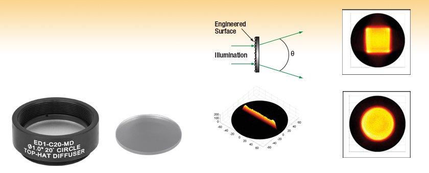
IntroductionThese Polymer Engineered Diffusers® are designed to create non-Gaussian intensity distributions in circular or square beam profiles that diverge from the plane of incidence. Below, to the left of the page, are the theoretical approximations of the intensity through the center of the diverging beam profile when illuminating the engineered diffusers with a 633 nm collimated beam. To the right are data compiled from independent tests with laser wavelengths of 488 nm, 637 nm, 785 nm, and 1064 nm to demonstrate the change in output profile with wavelength. The highlighted region of each graph denotes the divergence angle of the engineered diffuser. At the bottom of this tab is a description of the laboratory setup and procedure used to collect these data and the results.
FabricationThe master microlens array is produced by a laser writing system developed by VIAVI Solutions, Inc. This system exposes a thick layer of photoresist point-by-point in a raster scan mode, as shown to the left. By modulating the intensity of the laser beam as it is scanned, the degree to which the photoresist is exposed can be varied. A deeply textured, engineered surface is the result, as shown above in the two SEM images of the surface topography.
Image taken with camera at the same location, with same focal length, but using shift instead of rotating the camera. Notice that we no longer suffer from perspective distortion.
_Focal Length = 24mm â Focal length changed, no camera movement. Notice the red cylinder still ½ the height of the green/yellow cylinder, but more of the background is exposed._
Engineered Diffuser® TechnologyThorlabs' Engineered Diffusers provide advanced beam shaping that leads to significant performance enhancements for applications as diverse as lithographic systems, outdoor lighting, displays, backlighting, display brightness enhancement, and projection screens.
ProcedureFour wavelengths of light were chosen for study: 488 nm, 637 nm, 785 nm, and 1064 nm. These were prepared using the equipment to the right (a full list of all parts used can be found under the photo of the Experimental Set Up). The optical path was approximately 35 cm above the surface of the breadboard; it began when fiber-coupled light sources were collimated with triplet collimators, using a design wavelength as close to the source wavelength as possible. In free space, the beams were incident upon one of the Polymer Engineered Diffusers. The exiting divergent profile was isolated and focused by an LA1304 plano-convex lens attached to an SM05L20 lens tube. The signal was sampled every 0.5° by a SM05PD1A photodiode. This assembly was mounted on the end of an XT34-500 rail. The opposite end of the rail was mounted to a previous-generation NR360Sa rotation stage centered with the engineered diffuser under test in order to sweep the detector and lens assembly through the center of the profile, as illustrated below, and plot normalized intensity versus output angle. The distance between the diffuser and the detector was approximately 43 cm. The output angle was defined with respect to the original optical axis when the diffuser was not within the path. In order to control for ambient light, a 1 kHz sine wave was used to modulate the drive current applied to the laser diode and the signal was acquired with a lock-in amplifier. A LabVIEW program was written to control the setup and acquire the data.
Homogeneous diffusers made of, for example, ground glass, opal glass, or holographic elements, consist of repeating, uniform surface patterns across the entire clear aperture that provide only limited control over the shape and intensity profile of the illuminated area, causing the incident light to be used inefficiently. In addition, holographic diffusers are usually limited to monochromatic applications using coherent light. On the other hand, Engineered Diffusers consist of differing, individually manipulated microlens units that provide broadband compatibility and excellent control over the light distribution and beam profile.
Image taken by rotating the camera up to capture the full height of the subjects. Notice the significant perspective distortion.
Opticaldiffuser
Changing the focal length or FOV is only one way to control the size of an object in the frame ("zooming in" or "zooming out"). The other way is to actually move the camera closer or farther away from the subject. Note that these are not equivalent and will result in very different looks. While the focal length/FOV changes the size of a single object in the frame, the relative sizes of 2 objects in the scene depends ONLY on the location of the camera relative to these objects. Thus framing a scene with multiple subjects involves positioning the camera to achieve the desired blocking and relative sizes of the subjects, THEN adjusting the Focal Length to achieve the desired overall framing. In the following example, the two cylinders in the scene are the same height (10). We position the camera such that the red cylinder is approximately ½ the size of the green/yellow cylinder. We then show the effect of first making the focal length wider and of moving the camera


 Ms.Cici
 8618319014500