
Ra & RMS: Calculating Surface Roughness - surface roughness
Direct driverotationstage
SoftwareThis stage can be operated with the user friendly Kinesis software package, which allows the user to quickly set up complex move sequences. It also features .NET controls which can be used by 3rd party developers working in the latest C#, Visual Basic, LabVIEW™ or any .NET compatible languages to create custom applications. All relevant operating parameters are set automatically by the software for Thorlabs stage and actuator products. For more details, please see the Kinesis Software and Kinesis Tutorials tabs.
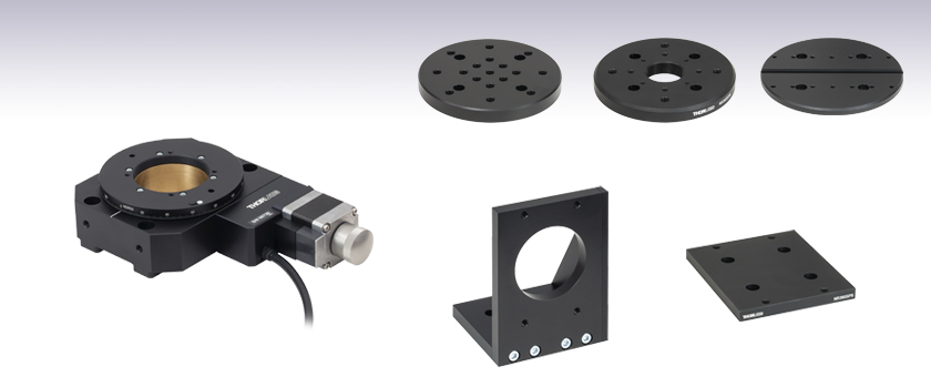
The HDR50(/M) Heavy-Duty Rotation Stage provides motorized, continuous rotation and can support loads up to 50 kg (110 lbs). It incorporates a micro-stepping motor, worm gear assembly, precision bearings, and a low-profile design with a height of 44.0 mm. The central aperture features an SM2 thread on the rotating and the non-rotating parts, making the stage compatible with our SM2 lens tubes. The stage has four 1/4" (M6) countersunk holes that allow it to be secured directly to a breadboard. The holes are spaced apart such that an imperial stage may also be mounted to a metric breadboard and vice versa. The stage can also be post mounted using the six 1/4"-20 (M6) side-located mounting holes.
For a collection of example projects that can be compiled and run to demonstrate the different ways in which developers can build on the Kinesis motion control libraries, click on the links below. Please note that a separate integrated development environment (IDE) (e.g., Microsoft Visual Studio) will be required to execute the Quick Start examples. The C# example projects can be executed using the included .NET controls in the Kinesis software package (see the Kinesis Software tab for details).
Motorized RotationMount
In addition to the discrete pixels, other factors such as the quality of the imaging system and camera noise all limit the accurate reproduction of an object. The resolution and performance of a camera within an optical system can be characterized by a quantity known as the modulation transfer function (MTF), which is a measurement of the camera and optical system’s ability to transfer contrast from the specimen to the intermediate image plane at a specific resolution. Computation of the modulation transfer function is a mechanism that is often utilized by optical manufacturers to incorporate resolution and contrast data into a single specification. This concept is derived from standard conventions utilized in electrical engineering that relate the degree of modulation of an output signal to a function of the signal frequency.
It is only when the object image covers three pixels do we start to obtain an image that is more faithfully reproduced, and clearly represents a circular object. The quality of the image is also now independent of where the object image is centred, at a pixel centre or at the vertex of pixels. Nyquist's theorem, which states that the frequency of the digital sample should be twice that of the analog frequency, is typically cited to recommend a "sampling rate" of 2 pixels relative to the object image size. The Nyquist theorem deals with 2-dimensional signals such as audio and electrical signals and it is unsuitable for an image, which has three dimensions of intensity versus x and y spatial dimensions.
LabVIEWLabVIEW can be used to communicate with any Kinesis-based controller via .NET controls. In LabVIEW, you build a user interface, known as a front panel, with a set of tools and objects and then add code using graphical representations of functions to control the front panel objects. The LabVIEW tutorial, provided below, provides some information on using the .NET controls to create control GUIs for Kinesis-driven devices within LabVIEW. It includes an overview with basic information about using controllers in LabVIEW and explains the setup procedure that needs to be completed before using a LabVIEW GUI to operate a device.
Thorlabs' Kinesis® software features new .NET controls which can be used by third-party developers working in the latest C#, Visual Basic, LabVIEW™, or any .NET compatible languages to create custom applications.
Motorized RotationStage Thorlabs
Consider a projected image of a circular object that has a diameter smaller than a pixel. If the image falls directly in the centre of a pixel then the camera will reproduce the object as a square of 1 pixel. Even if the object is imaged onto the vertices of 4 pixels the object will still be reproduced as a square only dimmer - not a faithful reproduction. If the diameter of the projected image is equivalent to one or even two pixel diagonals the image reproduction is still not a faithful reproduction of the object and critically varies on whether the centre of the image projection falls on either the centre of a pixel or at the vertex of pixels.
The software package allows two methods of usage: graphical user interface (GUI) utilities for direct interaction with and control of the controllers 'out of the box', and a set of programming interfaces that allow custom-integrated positioning and alignment solutions to be easily programmed in the development language of choice.
Thorlabs'RotationStage
The NR360SP2(/M) vertical mounting bracket allows the HDR50(/M) stage or the retired NR360S(/M) stage to be mounted in a vertical orientation. The Ø2.68" bore allows an SM2 lens tube attached to the bottom of the stage to pass through the bracket. The bracket can be secured to an optical table or optical breadboard using an array of seven 1/4" (M6) counterbored holes. Mounting the HDR50(/M) stage to the bracket requires four 1/4"-20 (M6) cap screws (not included) that are at least 1.5" (35 mm) long.
Motorized RotationMount optics
Andor’s iKon-M 934 low noise CCD camera series are designed to offer the ultimate in high-sensitivity, low noise performance, ideal for demanding imaging applications. These high…
NewportRotationStage

Andor’s iKon-L High Dynamic Range CCD camera offers outstanding resolution, field of view, sensitivity and dynamic range performance. It boast a proprietary large area 5-stage TE…
The Kinesis Software features .NET controls which can be used by 3rd party developers working in the latest C#, Visual Basic, LabVIEW™, or any .NET compatible languages to create custom applications. Low-level DLL libraries are included for applications not expected to use the .NET framework and APIs are included with each install. A Central Sequence Manager supports integration and synchronization of all Thorlabs motion control hardware.
A typical MTF curve for a CCD camera with a 10x10 and 20x20 micron pixels is shown below right. The spatial frequency of sine waves projected onto the sensor surface is plotted on the abscissa and the resultant modulation percentage on the ordinate. The limiting resolution is normally defined as the 3 percent modulation level.
ManualRotationStage
By providing this common software platform, Thorlabs has ensured that users can mix and match any of our motion control devices in a single application, while only having to learn a single set of software tools. In this way, it is perfectly feasible to combine any of the controllers from single-axis to multi-axis systems and control all from a single, PC-based unified software interface.
The HDR50(/M) stage can be mounted directly to a breadboard using 1/4"-20 (M6) cap screws (not included) that are at least 1.5" (35 mm) long. It can also be mounted vertically using the holes on each side face or by using the NR360SP2 bracket sold below. The NR360SP5 adapter enables the HDR50 stage to be mounted to an LNR50 or NRT Series Translation Stage.
AccessoriesWe offer several types of top plate adapters which mount to the rotating world of the HDR50(/M) stage using 8-32 (M4) screws. We also offer two mounting adapters: the NR360SP2 bracket is designed for secure vertical mounting of the stage and the NR360SP5 adapter enables the HDR50 rotation stage to be mounted to select translation stages.
C#This programming language is designed to allow multiple programming paradigms, or languages, to be used, thus allowing for complex problems to be solved in an easy or efficient manner. It encompasses typing, imperative, declarative, functional, generic, object-oriented, and component-oriented programming. By providing functionality with this common software platform, Thorlabs has ensured that users can easily mix and match any of the Kinesis controllers in a single application, while only having to learn a single set of software tools. In this way, it is perfectly feasible to combine any of the controllers from the low-powered, single-axis to the high-powered, multi-axis systems and control all from a single, PC-based unified software interface.The Kinesis System Software allows two methods of usage: graphical user interface (GUI) utilities for direct interaction and control of the controllers 'out of the box', and a set of programming interfaces that allow custom-integrated positioning and alignment solutions to be easily programmed in the development language of choice.
Adequate resolution of an object can only be achieved if at least two samples are made for each resolvable unit (many investigators prefer three samples per resolvable unit to ensure sufficient sampling). In the case of the epi-fluorescence microscope, the resolvable unit from the Abbe diffraction limit at a wavelength of 550 nanometers using a 1.25 numerical aperture lens is 0.27 microns. If a 100x objective is employed, the projected size of a diffraction-limited spot on the face of the CCD would be 27 microns. A sensor size of 13 x 13 micron pixels would just allow the optical and electronic resolution to be matched, with a 9 x 9 micron pixel preferred. Although small sensors in a CCD improve spatial resolution, they also limit the dynamic range of the device.
The resolution of a CCD is a function of the number of pixels and their size relative to the projected image. CCD arrays of over 1,000 x 1,000 sensors (1 Mega-pixel) are now commonplace in scientific cameras. The trend in cameras is for the sensor size to decrease, and cameras with pixels as small as 4 x 4 microns are currently available in the consumer market. Before we consider the most appropriate pixel size of a particular application, it is important to consider the relative size of projected image to the pixel size to obtain a satisfactory reproduction of the image.
Motorized rotationstages
The NR360SP5(/M) mounting adapter allows the HDR50(/M) stage or the retired NR360S(/M) stage to be mounted on top of an LNR50 Series Stage, NRT100 Stage, or an NRT150 Stage, as shown in the photo to the right. This adapter requires four 1/4"-20 (M6), 3/8" (10 mm) long cap screws and four 1/4"-20 (M6), 1.5" (35 mm) long cap screws (not included).
The HDR50(/M) Heavy-Duty Rotation Stage features SM2-threaded central apertures on the rotating and non-rotating worlds (illustrated in the diagram to the right). The threaded section of the rotating world is 0.27" (6.9 mm) deep and the threaded section of the non-rotating world on the bottom side is 0.16" (4.0 mm) deep. Other mounting features are available using the top plate adapters below. These adapters attach using the 8-32 (M4) tapped holes in the stage's rotating world.
Thorlabs offers a wide variety of manual and motorized rotation mounts and stages. Rotation mounts are designed with an inner bore to mount a Ø1/2", Ø1", or Ø2" optic, while rotation stages are designed with mounting taps to attach a variety of components or systems. Motorized options are powered by a DC Servo motor, 2 phase stepper motor, piezo inertia motor, or an Elliptec™ resonant piezo motor. Each offers 360° of continuous rotation.
Thorlabs offers the Kinesis® software package to drive our wide range of motion controllers. The software can be used to control devices in the Kinesis family, which covers a wide variety of motion controllers ranging from small, low-powered, single-channel drivers (such as the K-Cubes™) to high-power, multi-channel benchtop units and modular 19" rack nanopositioning systems (the MMR60x Rack System).
These top plate adapters provide additional mounting features for our HDR50(/M) Rotation Stage. The plates mount to the moving world at the top of the stage using four included 8-32 (M4) screws. Note that while imperial adapters come with imperial hardware and metric adapters come with metric hardware, the plates themselves are compatible with either type of stage. For example, an imperial adapter may be attached to a metric stage using four M4 screws. These adapters are also compatible with the retired NR360S(/M) Stage.


 Ms.Cici
 8618319014500