
Properties of Microscope Objectives - objective power
Grating couplerLumerical
If you are new to the finite-difference time-domain (FDTD) method, we highly recommend going through our FDTD101 tutorials.
Grating couplertypes
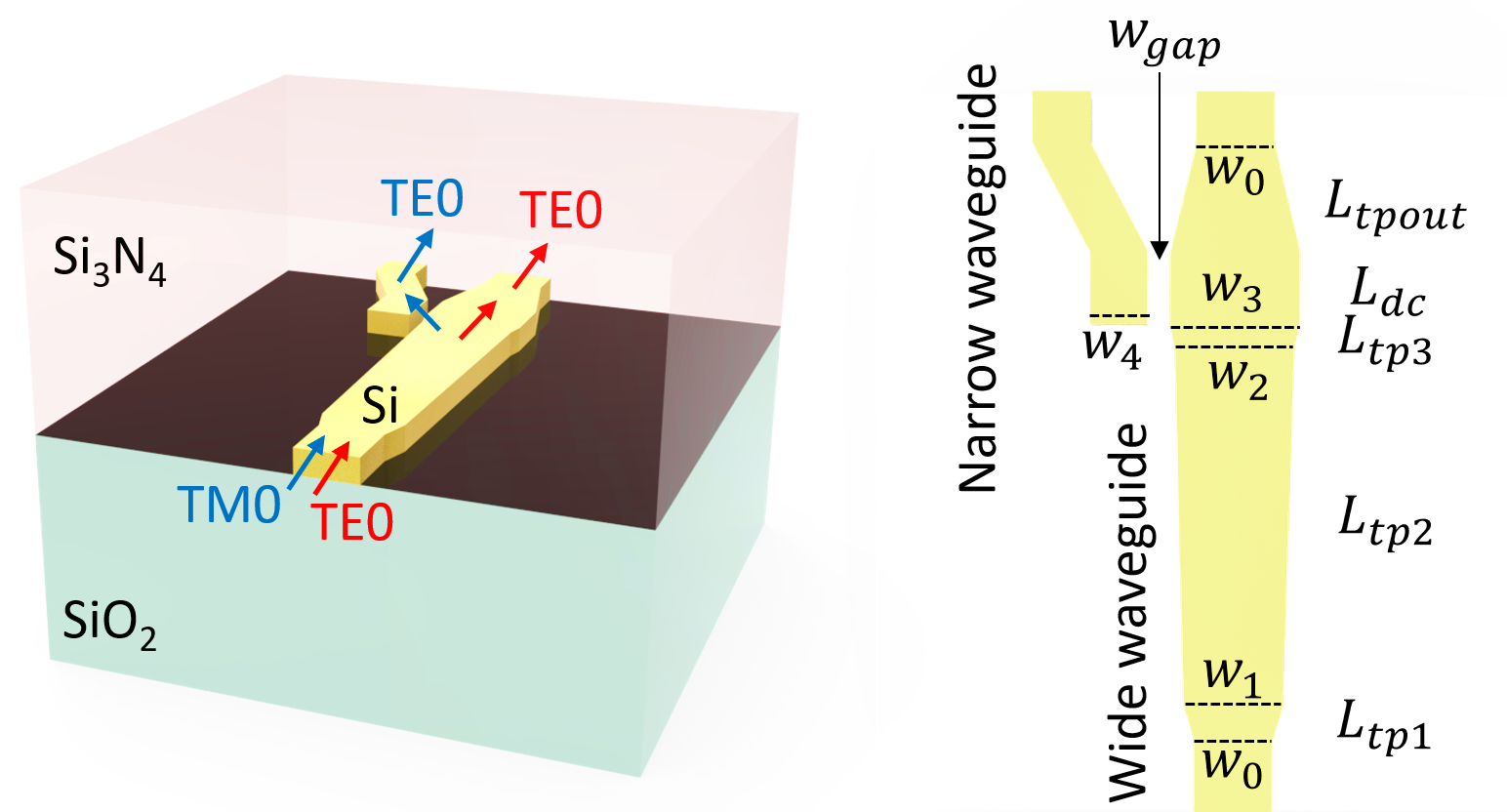
To determine the pitch of the waveguide for a given design angle, we need to compute the effective index of the waveguide mode being coupled into. For this, we set up a simple simulation of the coupler region and use the mode solver to get the effective index. We will not run this simulation, we just add a ModeMonitor object in order to construct and run the mode solver below, and get the effective index of the wide-waveguide region.
A basic schematic of the design is shown below. The simulation is about 19um x 4um x 5um with a wavelength of 1.55um and takes about 1 minute to simulate 10,000 time steps.
Note: because the simulation is just being used for the mode solver, we can safely ignore the warning about lack of sources.
Grating couplerdesign
We can also run the coupler in the opposite way, injecting a Gaussian beam from above and monitoring the transmission into the waveguide. We will use the measured angle rather than the design angle to see the highest in-coupling efficiency that we can obtain.
The coupler has close to 5% in-coupling efficiency, and we did not put any effort into optimizing it beyond just defining the grating pitch to target the correct angle!
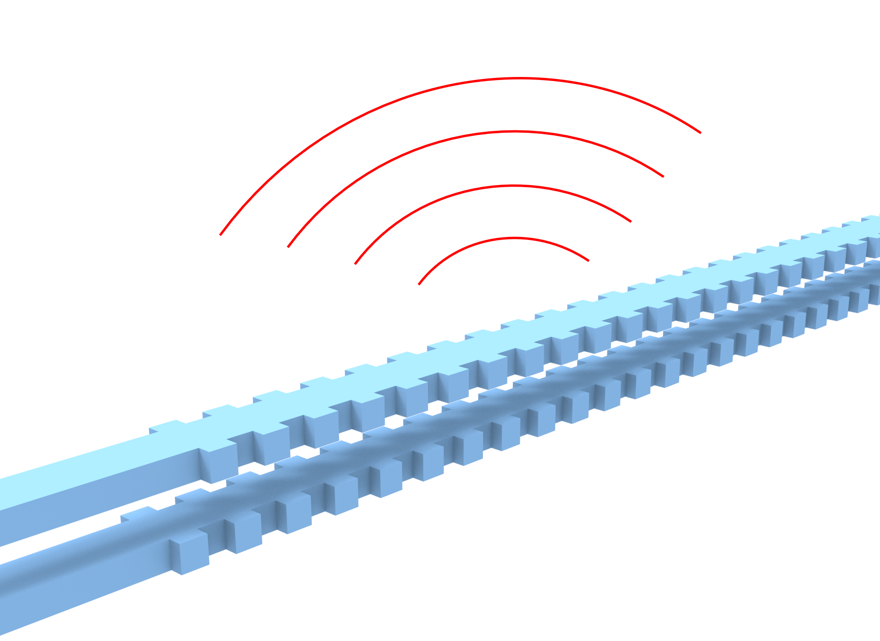
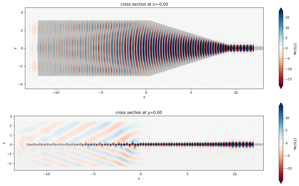
In the simulation, we inject a modal source into the waveguide and propagate it towards the grating structure. The radiation from the grating coupler is then measured with a near field monitor and we use a far field projection to inspect the angular dependence of the radiation.
Grating couplerdiagram
Grating couplertheory
Example Library / Passive Photonic Integrated Circuit Components / Uniform grating coupler
Enter your email address below to receive the presentation slides. In the future, weâll share you very few emails when we have new tutorial release, development updates, valuable toolkits and technical guidance . You can unsubscribe at any time by clicking the link at the bottom of every email. Weâll never share your information.
Grating couplerformula
In addition to the uniform grating coupler modeled here, we also studied a focusing apodized grating coupler and an inverse designed compact grating coupler in our case studies. Besides grating couplers, we have also investigated an inverse taper edge coupler.
The agreement between the target angle and the actual emission angle of the coupler is good. The small difference comes from the fact that the design is very sensitive to the value of the effective index that we use in the coupler region, and that value depends on which waveguide height we pick in that region: the one with the grating comb, or without. In our setup, we used a thickness that is at the mid-point, but this is a heuristic choice which results in the small final mismatch in angles observed here.
Now we use the Tidy3D's FieldProjector to compute the anglular dependence of the far field scattering based on the near field monitor.


 Ms.Cici
 8618319014500