
Profiling a Gaussian Laser Beam - gaussian laser beam
Retainer Clip C · Easy to install · Made of stainless steel and durable · Used to hold components securely in a place. C Clip is a type of fastener ...
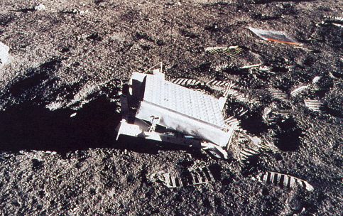
The Apollo 14 retroreflector array is very much like the Apollo 11 array in design: 100 3.8 cm reflectors in a 10×10 square pattern. Unlike the picture of the Aollo 11 array, this one has sunlight on its face, enabling a better view of the array of corner cubes. Is that a ziploc bag in the background? Apollo 15 A close-up of the Apollo 15 array, which has 300 3.8 cm corner cubes in a hexagonal array. Because this reflector is three times larger than the previous two, it gets preferential treatment by the photon-challenged LLR stations currently in operation. As of 1994, 6,300 of the 8,400 range measurements (75%) had been made to the Apollo 15 array. APOLLO will have much greater sensitivity, and will consequently visit the various retroreflectors in a more uniformly distributed manner. Lunokhod The Soviets landed two rovers on the moon, called Lunokhod 1 and Lunokhod 2, on the Luna 17 and Luna 21 missions in 1970 and 1973, respectively. These rovers were equipped with small retroreflector arrays each consisting of 14 corner cubes of triangular configuration (not cut into a circle—imagine slicing off the corner of a cube with a knife). Each reflector is 11 cm on a side for a total package 44 cm long and 19 cm across. The picture at right of the Lunokhod rover shows the reflector jutting out in front (left). Lunokhod 1 was successfully ranged during its maneuvering phase, but then was not seen for almost 40 years until our project (with the help of the Lunar Reconnaissance Orbiter) re-discovered the reflector in April 2010. Now both Lunokhod reflectors are routinely used, though the large size of the cubes makes them more susceptible to thermal distortions, so that the return is about 30 times weaker in lunar daylight than in lunar night. On the other hand, the larger size makes for a tighter diffraction pattern during lunar night, so the effective cross-section becomes slightly larger than the Apollo 11 and Apollo 14 arrays during these periods. Lunokhod 1 plays by this rule, but Lunokhod 2 has become about five times weaker than its twin reflector. Location of the reflector landing sites APOLLO main page.
A basic compound microscope could consist of just two elements acting in relay, the objective and the eyepiece. The objective relays a real image to the eyepiece, while magnifying that image anywhere from 4-100x. The eyepiece magnifies the real image received typically by another 10x, and conveys a virtual image to the sensor.
There are two major specifications for a microscope: the magnification power and the resolution. The magnification tells us how much larger the image is made to appear. The resolution tells us how far away two points must be to be distinguishable. The smaller the resolution, the larger the resolving power of the microscope. The highest resolution you can get with a light microscope is 0.2 microns (0.2 microns), but this depends on the quality of both the objective and eyepiece.
Tiffen Lens Cleaning Paper should be an integral part of any scope or gear kit. These lint-free tissues will help keep your valuable optics free of smudges ...
While a magnifying glass consists of just one lens element and can magnify any element placed within its focal length, a compound lens, by definition, contains multiple lens elements. A relay lens system is used to convey the image of the object to the eye or, in some cases, to camera and video sensors.
What are the3objectivelenseson a microscope
While most microscope objectives are designed to work with air between the objective and cover glass, objectives lenses designed for higher NA and greater magnification sometimes use an alternate immersion medium. For instance, a typical oil immersion object is meant to be used with an oil with refractive index of 1.51.
Objective lensmagnification
At Avantier we produce high quality microscope objectives lenses, ocular lenses, and other imaging systems. We are also able to provide custom designed optical lenses as needed. Chromatic focus shift, working distance, image quality, lens mount, field of view, and antireflective coatings are just a few of the parameters we can work with to create an ideal objective for your application. Contact us today to learn more about how we can help you meet your goals.
Aug 19, 2024 — Lasers are categorized into thousands of types based on the lasing medium they use. The main categories—gas, liquid, solid-state, ...
A basic achromatic objective is a refractive objective that consists of just an achromatic lens and a meniscus lens, mounted within appropriate housing. The design is meant to limit the effects of chromatic and spherical aberration as they bring two wavelengths of light to focus in the same plane. Plan Apochromat objectives can be much more complex with up to fifteen elements. They can be quite expensive, as would be expected from their complexity.
A microscope is an optical device designed to magnify the image of an object, enabling details indiscernible to the human eye to be differentiated. A microscope may project the image onto the human eye or onto a camera or video device.
Historically microscopes were simple devices composed of two elements. Like a magnifying glass today, they produced a larger image of an object placed within the field of view. Today, microscopes are usually complex assemblies that include an array of lenses, filters, polarizers, and beamsplitters. Illumination is arranged to provide enough light for a clear image, and sensors are used to ‘see’ the object.
An microscope objective may be either reflective or refractive. It may also be either finite conjugate or infinite conjugate.
Apollo 15 A close-up of the Apollo 15 array, which has 300 3.8 cm corner cubes in a hexagonal array. Because this reflector is three times larger than the previous two, it gets preferential treatment by the photon-challenged LLR stations currently in operation. As of 1994, 6,300 of the 8,400 range measurements (75%) had been made to the Apollo 15 array. APOLLO will have much greater sensitivity, and will consequently visit the various retroreflectors in a more uniformly distributed manner. Lunokhod The Soviets landed two rovers on the moon, called Lunokhod 1 and Lunokhod 2, on the Luna 17 and Luna 21 missions in 1970 and 1973, respectively. These rovers were equipped with small retroreflector arrays each consisting of 14 corner cubes of triangular configuration (not cut into a circle—imagine slicing off the corner of a cube with a knife). Each reflector is 11 cm on a side for a total package 44 cm long and 19 cm across. The picture at right of the Lunokhod rover shows the reflector jutting out in front (left). Lunokhod 1 was successfully ranged during its maneuvering phase, but then was not seen for almost 40 years until our project (with the help of the Lunar Reconnaissance Orbiter) re-discovered the reflector in April 2010. Now both Lunokhod reflectors are routinely used, though the large size of the cubes makes them more susceptible to thermal distortions, so that the return is about 30 times weaker in lunar daylight than in lunar night. On the other hand, the larger size makes for a tighter diffraction pattern during lunar night, so the effective cross-section becomes slightly larger than the Apollo 11 and Apollo 14 arrays during these periods. Lunokhod 1 plays by this rule, but Lunokhod 2 has become about five times weaker than its twin reflector. Location of the reflector landing sites APOLLO main page.
What are the objective lens on a microscopeexplain
Folding Pocket Magnifiers. Eschenbach pocket magnifiers are compact, lightweight magnifiers that can be taken with you anywhere. These types ...
The parfocal length of a microscope is defined as the distance between the object being studied and the objective mounting plane.
A close-up of the Apollo 15 array, which has 300 3.8 cm corner cubes in a hexagonal array. Because this reflector is three times larger than the previous two, it gets preferential treatment by the photon-challenged LLR stations currently in operation. As of 1994, 6,300 of the 8,400 range measurements (75%) had been made to the Apollo 15 array. APOLLO will have much greater sensitivity, and will consequently visit the various retroreflectors in a more uniformly distributed manner. Lunokhod The Soviets landed two rovers on the moon, called Lunokhod 1 and Lunokhod 2, on the Luna 17 and Luna 21 missions in 1970 and 1973, respectively. These rovers were equipped with small retroreflector arrays each consisting of 14 corner cubes of triangular configuration (not cut into a circle—imagine slicing off the corner of a cube with a knife). Each reflector is 11 cm on a side for a total package 44 cm long and 19 cm across. The picture at right of the Lunokhod rover shows the reflector jutting out in front (left). Lunokhod 1 was successfully ranged during its maneuvering phase, but then was not seen for almost 40 years until our project (with the help of the Lunar Reconnaissance Orbiter) re-discovered the reflector in April 2010. Now both Lunokhod reflectors are routinely used, though the large size of the cubes makes them more susceptible to thermal distortions, so that the return is about 30 times weaker in lunar daylight than in lunar night. On the other hand, the larger size makes for a tighter diffraction pattern during lunar night, so the effective cross-section becomes slightly larger than the Apollo 11 and Apollo 14 arrays during these periods. Lunokhod 1 plays by this rule, but Lunokhod 2 has become about five times weaker than its twin reflector. Location of the reflector landing sites APOLLO main page.
High powerobjective microscopefunction
Most microscopes rely on background illumination such as daylight or a lightbulb rather than a dedicated light source. In brightfield illumination (also known as Koehler illumination), two convex lenses, a collector lens and a condenser lens, are placed so as to saturate the specimen with external light admitted into the microscope from behind. This provides a bright, even, steady light throughout the system.
TASK QSRs are versatile, strong, and easy to use. QSRs are indispensable when installing drywall, crown moulding, cabinets, trim, sinks, and more.
This semi-apochromat objective series provides flat images and high transmission up to the near-infrared region of the spectrum. Acquiring sharp, clear images ...
High powerobjective lens
The Apollo 11 retroreflector array, consisting of 100 corner-cube prisms in a 10×10 array. Each corner cube is made of fused silica (quartz) and is 3.8 cm in diameter. The palette is 0.45 meters square, and carefully designed to minimize thermal gradients across the corner cubes as the array is slammed into and out of the sun's rays as the moon's phase changes. This prevents thermal distortions from seriously degrading the amount of light returned by the reflectors. Apollo 14 The Apollo 14 retroreflector array is very much like the Apollo 11 array in design: 100 3.8 cm reflectors in a 10×10 square pattern. Unlike the picture of the Aollo 11 array, this one has sunlight on its face, enabling a better view of the array of corner cubes. Is that a ziploc bag in the background? Apollo 15 A close-up of the Apollo 15 array, which has 300 3.8 cm corner cubes in a hexagonal array. Because this reflector is three times larger than the previous two, it gets preferential treatment by the photon-challenged LLR stations currently in operation. As of 1994, 6,300 of the 8,400 range measurements (75%) had been made to the Apollo 15 array. APOLLO will have much greater sensitivity, and will consequently visit the various retroreflectors in a more uniformly distributed manner. Lunokhod The Soviets landed two rovers on the moon, called Lunokhod 1 and Lunokhod 2, on the Luna 17 and Luna 21 missions in 1970 and 1973, respectively. These rovers were equipped with small retroreflector arrays each consisting of 14 corner cubes of triangular configuration (not cut into a circle—imagine slicing off the corner of a cube with a knife). Each reflector is 11 cm on a side for a total package 44 cm long and 19 cm across. The picture at right of the Lunokhod rover shows the reflector jutting out in front (left). Lunokhod 1 was successfully ranged during its maneuvering phase, but then was not seen for almost 40 years until our project (with the help of the Lunar Reconnaissance Orbiter) re-discovered the reflector in April 2010. Now both Lunokhod reflectors are routinely used, though the large size of the cubes makes them more susceptible to thermal distortions, so that the return is about 30 times weaker in lunar daylight than in lunar night. On the other hand, the larger size makes for a tighter diffraction pattern during lunar night, so the effective cross-section becomes slightly larger than the Apollo 11 and Apollo 14 arrays during these periods. Lunokhod 1 plays by this rule, but Lunokhod 2 has become about five times weaker than its twin reflector. Location of the reflector landing sites APOLLO main page.
The optical performance of an objective is dependent largely on the optical aberration correction, and these corrections are also central to image quality and measurement accuracy. Objective lenses are classified as achromat, plan achromat, plan semi apochromat, plan apochromat, and super apochromat depending on the degree of correction.
In modern microscopes, neither the eyepiece nor the microscope objective is a simple lens. Instead, a combination of carefully chosen optical components work together to create a high quality magnified image. A basic compound microscope can magnify up to about 1000x. If you need higher magnification, you may wish to use an electron microscope, which can magnify up to a million times.
Major League Hacking (MLH) on the 2017 30 Under 30 - Education - MLH is a student hackathon league that supports over 200 weekend-long invention ...
The field of view (FOV) of a microscope is simply the area of the object that can be imaged at any given time. For an infinity-corrected objective, this will be determined by the objective magnification and focal length of the tube lens. Where a camera is used the FOV also depends on sensor size.
Although today’s microscopes are usually far more powerful than the microscopes used historically, they are used for much the same purpose: viewing objects that would otherwise be indiscernible to the human eye. Here we’ll start with a basic compound microscope and go on to explore the components and function of larger more complex microscopes. We’ll also take an in-depth look at one of the key parts of a microscope, the objective lens.
Apollo 11 The Apollo 11 retroreflector array, consisting of 100 corner-cube prisms in a 10×10 array. Each corner cube is made of fused silica (quartz) and is 3.8 cm in diameter. The palette is 0.45 meters square, and carefully designed to minimize thermal gradients across the corner cubes as the array is slammed into and out of the sun's rays as the moon's phase changes. This prevents thermal distortions from seriously degrading the amount of light returned by the reflectors. Apollo 14 The Apollo 14 retroreflector array is very much like the Apollo 11 array in design: 100 3.8 cm reflectors in a 10×10 square pattern. Unlike the picture of the Aollo 11 array, this one has sunlight on its face, enabling a better view of the array of corner cubes. Is that a ziploc bag in the background? Apollo 15 A close-up of the Apollo 15 array, which has 300 3.8 cm corner cubes in a hexagonal array. Because this reflector is three times larger than the previous two, it gets preferential treatment by the photon-challenged LLR stations currently in operation. As of 1994, 6,300 of the 8,400 range measurements (75%) had been made to the Apollo 15 array. APOLLO will have much greater sensitivity, and will consequently visit the various retroreflectors in a more uniformly distributed manner. Lunokhod The Soviets landed two rovers on the moon, called Lunokhod 1 and Lunokhod 2, on the Luna 17 and Luna 21 missions in 1970 and 1973, respectively. These rovers were equipped with small retroreflector arrays each consisting of 14 corner cubes of triangular configuration (not cut into a circle—imagine slicing off the corner of a cube with a knife). Each reflector is 11 cm on a side for a total package 44 cm long and 19 cm across. The picture at right of the Lunokhod rover shows the reflector jutting out in front (left). Lunokhod 1 was successfully ranged during its maneuvering phase, but then was not seen for almost 40 years until our project (with the help of the Lunar Reconnaissance Orbiter) re-discovered the reflector in April 2010. Now both Lunokhod reflectors are routinely used, though the large size of the cubes makes them more susceptible to thermal distortions, so that the return is about 30 times weaker in lunar daylight than in lunar night. On the other hand, the larger size makes for a tighter diffraction pattern during lunar night, so the effective cross-section becomes slightly larger than the Apollo 11 and Apollo 14 arrays during these periods. Lunokhod 1 plays by this rule, but Lunokhod 2 has become about five times weaker than its twin reflector. Location of the reflector landing sites APOLLO main page.
There are some important specifications and terminology you’ll want to be aware of when designing a microscope or ordering microscope objectives. Here is a list of key terminology.
Twist-On Collimators for VIS-NIR (425 nm – 1550 nm) · connect quickly to FC or SMA connectorized fiber cables to produce a collimated beam. · contain a micro ...
Types ofobjectivelenses
Both the objective lens and the eyepiece also contribute to the overall magnification of the system. If an objective lens magnifies the object by 10x and the eyepiece by 2x, the microscope will magnify the object by 20. If the microscope lens magnifies the object by 10x and the eyepiece by 10x, the microscope will magnify the object by 100x. This multiplicative relationship is the key to the power of microscopes, and the prime reason they perform so much better than simply magnifying glasses.
Lunokhod The Soviets landed two rovers on the moon, called Lunokhod 1 and Lunokhod 2, on the Luna 17 and Luna 21 missions in 1970 and 1973, respectively. These rovers were equipped with small retroreflector arrays each consisting of 14 corner cubes of triangular configuration (not cut into a circle—imagine slicing off the corner of a cube with a knife). Each reflector is 11 cm on a side for a total package 44 cm long and 19 cm across. The picture at right of the Lunokhod rover shows the reflector jutting out in front (left). Lunokhod 1 was successfully ranged during its maneuvering phase, but then was not seen for almost 40 years until our project (with the help of the Lunar Reconnaissance Orbiter) re-discovered the reflector in April 2010. Now both Lunokhod reflectors are routinely used, though the large size of the cubes makes them more susceptible to thermal distortions, so that the return is about 30 times weaker in lunar daylight than in lunar night. On the other hand, the larger size makes for a tighter diffraction pattern during lunar night, so the effective cross-section becomes slightly larger than the Apollo 11 and Apollo 14 arrays during these periods. Lunokhod 1 plays by this rule, but Lunokhod 2 has become about five times weaker than its twin reflector. Location of the reflector landing sites APOLLO main page.
The eyepiece or ocular lens is the part of the microscope closest to your eye when you bend over to look at a specimen. An eyepiece usually consists of two lenses: a field lens and an eye lens. If a larger field of view is required, a more complex eyepiece that increases the field of view can be used instead.
The Soviets landed two rovers on the moon, called Lunokhod 1 and Lunokhod 2, on the Luna 17 and Luna 21 missions in 1970 and 1973, respectively. These rovers were equipped with small retroreflector arrays each consisting of 14 corner cubes of triangular configuration (not cut into a circle—imagine slicing off the corner of a cube with a knife). Each reflector is 11 cm on a side for a total package 44 cm long and 19 cm across. The picture at right of the Lunokhod rover shows the reflector jutting out in front (left). Lunokhod 1 was successfully ranged during its maneuvering phase, but then was not seen for almost 40 years until our project (with the help of the Lunar Reconnaissance Orbiter) re-discovered the reflector in April 2010. Now both Lunokhod reflectors are routinely used, though the large size of the cubes makes them more susceptible to thermal distortions, so that the return is about 30 times weaker in lunar daylight than in lunar night. On the other hand, the larger size makes for a tighter diffraction pattern during lunar night, so the effective cross-section becomes slightly larger than the Apollo 11 and Apollo 14 arrays during these periods. Lunokhod 1 plays by this rule, but Lunokhod 2 has become about five times weaker than its twin reflector. Location of the reflector landing sites APOLLO main page.
Objective lensfunction
Objective lens microscopefunction
Refractive objectives are so-called because the elements bend or refract light as it passes through the system. They are well suited to machine vision applications, as they can provide high resolution imaging of very small objects or ultra fine details. Each element within a refractive element is typically coated with an anti-reflective coating.
Apollo 14 The Apollo 14 retroreflector array is very much like the Apollo 11 array in design: 100 3.8 cm reflectors in a 10×10 square pattern. Unlike the picture of the Aollo 11 array, this one has sunlight on its face, enabling a better view of the array of corner cubes. Is that a ziploc bag in the background? Apollo 15 A close-up of the Apollo 15 array, which has 300 3.8 cm corner cubes in a hexagonal array. Because this reflector is three times larger than the previous two, it gets preferential treatment by the photon-challenged LLR stations currently in operation. As of 1994, 6,300 of the 8,400 range measurements (75%) had been made to the Apollo 15 array. APOLLO will have much greater sensitivity, and will consequently visit the various retroreflectors in a more uniformly distributed manner. Lunokhod The Soviets landed two rovers on the moon, called Lunokhod 1 and Lunokhod 2, on the Luna 17 and Luna 21 missions in 1970 and 1973, respectively. These rovers were equipped with small retroreflector arrays each consisting of 14 corner cubes of triangular configuration (not cut into a circle—imagine slicing off the corner of a cube with a knife). Each reflector is 11 cm on a side for a total package 44 cm long and 19 cm across. The picture at right of the Lunokhod rover shows the reflector jutting out in front (left). Lunokhod 1 was successfully ranged during its maneuvering phase, but then was not seen for almost 40 years until our project (with the help of the Lunar Reconnaissance Orbiter) re-discovered the reflector in April 2010. Now both Lunokhod reflectors are routinely used, though the large size of the cubes makes them more susceptible to thermal distortions, so that the return is about 30 times weaker in lunar daylight than in lunar night. On the other hand, the larger size makes for a tighter diffraction pattern during lunar night, so the effective cross-section becomes slightly larger than the Apollo 11 and Apollo 14 arrays during these periods. Lunokhod 1 plays by this rule, but Lunokhod 2 has become about five times weaker than its twin reflector. Location of the reflector landing sites APOLLO main page.
6mm Shaft (Stainless Steel, 50mm Length) ... These 6mm diameter shafts are made from stainless steel for superior strength and precision. Rockwell hardness is 83B ...
Numerical aperture NA denotes the light acceptance angle. Where θ is the maximum 1/2 acceptance ray angle of the objective and n is the index of refraction of the immersive medium, the NA can be denoted by
Microscope objective lenses are typically the most complex part of a microscope. Most microscopes will have three or four objectives lenses, mounted on a turntable for ease of use. A scanning objective lens will provide 4x magnification, a low power magnification lens will provide magnification of 10x, and a high power objective offers 40x magnification. For high magnification, you will need to use oil immersion objectives. These can provide up to 50x, 60x, or 100x magnification and increase the resolving power of the microscope, but they cannot be used on live specimens.
The working distance of a microscope is defined as the free distance between the objective lens and the object being studied. Low magnification objective lenses have a long working distance.
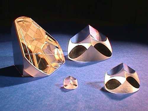
Retroreflectors, or corner-cube prisms, are optical devices that return any incident light back in exactly the direction from which it came. The central design concept is a trio of mutually perpendicular surfaces such as is found at the corner of a cube (look up into the corner of the room where the ceiling hits the walls). If these three surfaces are reflective, a light ray will bounce off each in turn, with the net result being a precise 180° turn. (Ever hit a racquetball right into the corner and had it come right back at you?). Retroreflectors are in tail-light covers (feel the sharp bumps on the inside of one), bike reflectors, and in paints for road signs (very tiny crystals). Apollo 11 The Apollo 11 retroreflector array, consisting of 100 corner-cube prisms in a 10×10 array. Each corner cube is made of fused silica (quartz) and is 3.8 cm in diameter. The palette is 0.45 meters square, and carefully designed to minimize thermal gradients across the corner cubes as the array is slammed into and out of the sun's rays as the moon's phase changes. This prevents thermal distortions from seriously degrading the amount of light returned by the reflectors. Apollo 14 The Apollo 14 retroreflector array is very much like the Apollo 11 array in design: 100 3.8 cm reflectors in a 10×10 square pattern. Unlike the picture of the Aollo 11 array, this one has sunlight on its face, enabling a better view of the array of corner cubes. Is that a ziploc bag in the background? Apollo 15 A close-up of the Apollo 15 array, which has 300 3.8 cm corner cubes in a hexagonal array. Because this reflector is three times larger than the previous two, it gets preferential treatment by the photon-challenged LLR stations currently in operation. As of 1994, 6,300 of the 8,400 range measurements (75%) had been made to the Apollo 15 array. APOLLO will have much greater sensitivity, and will consequently visit the various retroreflectors in a more uniformly distributed manner. Lunokhod The Soviets landed two rovers on the moon, called Lunokhod 1 and Lunokhod 2, on the Luna 17 and Luna 21 missions in 1970 and 1973, respectively. These rovers were equipped with small retroreflector arrays each consisting of 14 corner cubes of triangular configuration (not cut into a circle—imagine slicing off the corner of a cube with a knife). Each reflector is 11 cm on a side for a total package 44 cm long and 19 cm across. The picture at right of the Lunokhod rover shows the reflector jutting out in front (left). Lunokhod 1 was successfully ranged during its maneuvering phase, but then was not seen for almost 40 years until our project (with the help of the Lunar Reconnaissance Orbiter) re-discovered the reflector in April 2010. Now both Lunokhod reflectors are routinely used, though the large size of the cubes makes them more susceptible to thermal distortions, so that the return is about 30 times weaker in lunar daylight than in lunar night. On the other hand, the larger size makes for a tighter diffraction pattern during lunar night, so the effective cross-section becomes slightly larger than the Apollo 11 and Apollo 14 arrays during these periods. Lunokhod 1 plays by this rule, but Lunokhod 2 has become about five times weaker than its twin reflector. Location of the reflector landing sites APOLLO main page.
by F Théberge · 2006 · Cited by 451 — Our experiment shows that external focusing strongly influences the plasma density and the diameter of femtosecond Ti-sapphire laser ...
A reflective objective works by reflecting light rather than bending it. Primary and secondary mirror systems both magnify and relay the image of the object being studied. While reflective objectives are not as widely used as refractive objectives, they offer many benefits. They can work deeper in the UV or IR spectral regions, and they are not plagued with the same aberrations as refractive objectives. As a result, they tend to offer better resolving power.


 Ms.Cici
 8618319014500