
Possibly The Best Zoom Lens For Your DSLR - zoom lense
A previous study has indicated that radiographer awareness and dedication are the major influencing factors on collimation. 13 Better education on the use of anatomical landmarks and written collimation guidelines 14 may increase radiographer compliance with regard to collimation. Radiographer awareness and attitudes of radiation exposure can change with personalised audit feedback. 15
From the five projections, 1071 measurements were analysed. 416 (38.8%) of these measurements were less than or equal to the agreed reference standard. 655 (61.2%) were greater than the agreed reference standard.
Collimation is the limitation of the primary x‐ray beam by blade‐type diaphragms on the x‐ray tube. Collimation of the primary beam to the area of interest limits the radiation dose to the patient by limiting the amount of tissue that is exposed. Appropriate collimation has always been an important factor in image quality, as it reduces the amount of scatter produced, which increases image quality.
Collimationbinoculars
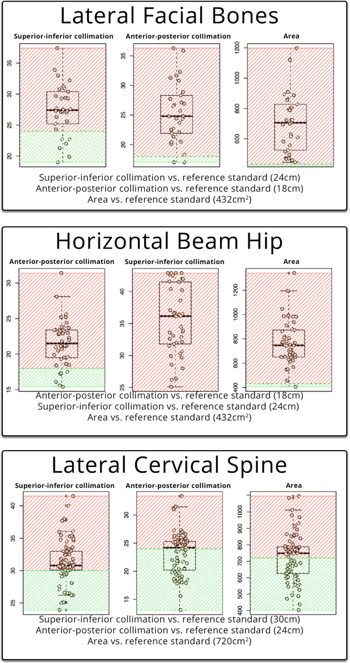
When measured against the reference standard, supero‐inferior collimation was lower or equal to the limit in a total of six patients (20%), whilst twenty‐four patients (80%) were above the limit. The antero‐posterior collimation was lower or equal to the limit in a total of two patients (6.67%), whilst twenty‐eight patients (93.3%) were above the limit. The EFOV was lower or equal to the limit in zero patients (0%), with all thirty (30) patients (100%) being above the limit.
When measured against the reference standard, antero‐posterior collimation was lower or equal to the limit in a total of six patients (14.29%), whilst thirty‐six patients (85.71%) were above the limit (Table 1). The supero‐inferior collimation was lower or equal to the limit in a total of zero patients (0%), whilst forty‐two patients (100%) were above the limit. The EFOV was lower or equal to the limit in one patient (2.38%), whilst forty‐one patients (97.62%) were above the limit.
- Fixing method : 2 Fixing Hole - Power : DC 9V (AC220V 50/60 Hz Adapter) - Display - Absolute Optical Power : Max. 100 mW/cm2 (Standard) - Relative Power : Max. 100 % - Cumulative Time (unit : min)
Previous studies have shown that image quality has improved using tight collimation. 4 Larger collimation areas increase the amount of scatter produced, and this is particularly important on thicker body parts, such as the HBL hip. Scatter negatively impacts subject contrast 5 and spatial resolution. 6 Previous studies have demonstrated collimation can greatly reduce radiation dose and associated risks. 7
A total of one thousand and seventy‐one measurements were recorded. Four hundred sixteen measurements (38.8%) measured at or below the reference standard. Six hundred fifty‐five measurements (61.2%) measured above the reference standard. The results are available in Table 1.
One hundred thirteen examinations were assessed against the reference standard (24 cm × 30 cm = 720 cm2), the summary description can be seen in Table 1. The visualisation of the data is presented in Figure 1 against the reference standard (in green).
While pre‐set collimation field sizes are built into the machines, individual users can adjust the irradiated area manually. Collimation of the primary x‐ray beam remains the best practice for limiting the radiation field to comply with as low as reasonably achievable (ALARA) principles. 2
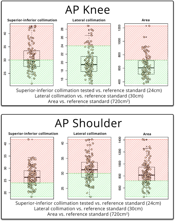
Supero‐inferior collimation was lower or equal to the standard in a total of thirty patients (26.55%), whilst eighty‐three patients (73.45%) were above the limit (Table 1). The lateral collimation was lower or equal to the limit in a total of forty‐six (46) patients (40.71%), whilst sixty‐seven patients (59.29%) were above the limit. The EFOV was lower or equal to the limit in a total of twenty‐eight patients (24.78%), whilst eighty‐five patients (75.22%) were above the limit.
Correspondence , Sally Ball, Department of Medical Imaging, Princess Alexandra Hospital, Brisbane, Australia. Tel: +61 07 31762971; E‐mail: sally.ball@health.qld.gov.au
Box and whisker plots of the lateral facial bones, horizontal beam hip and lateral cervical spine. Each dot represents an observation on the plot line. Green represents within the reference standard, red outside the reference standard.
Exposure creep, where radiographers pursuing high‐quality diagnostic images increase the exposure to the patient, has been well documented since the introduction of CR and DR technology. There is no visual ramification for an under‐ or over‐exposed x‐ray, and radiographers gradually increase exposures over time with no consequence to image quality. 11 However, the ability of radiographers to apply electronic cropping to an image leads to an increased area of exposure, resulting in an increase in dose to the patient and an increased amount of scatter reaching the detector, which results in overall poorer image quality, as demonstrated in Figures 3 and 4.
- Output - 0-5 V Voltage, 0.1A Max. (Depends on Absolute Optical Power) - 4-20 mA Current, 5 V (Depends on Absolute Optical Power) UV Radiometer
Collimationpronunciation
The reference standard was the corresponding cassette size used for the individual projection in film/screen or computed radiography (CR). The cassette size was chosen as the reference standard as it represents the largest collimated field required to demonstrate the anatomy in the projection. The null hypothesis was that the collimation was not greater than the maximum cassette size. The body parts were chosen to represent the axial and appendicular skeleton, with a variety of AP and lateral projections, that would traditionally have been taken on different cassette sizes.
Secure .gov websites use HTTPS A lock ( Lock Locked padlock icon ) or https:// means you've safely connected to the .gov website. Share sensitive information only on official, secure websites.
Collimation of the primary beam is considered the best practice for reducing radiation dose to patients by limiting the exposure to the anatomy of interest. As seen in Figure 5, utilising a ‘silver lining’ protocol, whereby the actual exposed area is demonstrated by a small distance between the collimation of the primary beam (creating a small white border around the radiograph), and the electronic cropping can serve as a quality control tool to encourage collimation of the primary beam to be used. 3 Sending images to PACS with ‘silver lining’ collimation, 2 would prevent radiographers masking over‐radiation exposure resulting from poor collimation. 2 Sending images such as Figure 4 to PACS with silver lining collimation would help identify areas of improvement with relation to collimation, centring and radiation hygiene. Protocols such as the suggested ‘silver lining’ protocol may be the most sure‐fire way to measure and ensure proper collimation of images whilst guaranteeing that all irradiated tissue is interpreted by an expert reader.
Seventy‐three examinations were assessed against the reference standard (30 cm x 24 cm = 720 cm2), the summary description can be seen in Table 1. The visualisation of the data is presented in Figure 2 against the reference standard (in green).
Forty‐two examinations were assessed against the reference standard (18 cm × 24 cm = 432 cm2), the summary description can be seen in Table 1. The visualisation of the data is presented in Figure 2 against the reference standard (in green).
Collimation meaningin surveying
When measured against the reference standard, supero‐inferior collimation was lower or equal to the limit seventeen patients (23.29%), whilst fifty‐six patients (76.71%) were above the limit. The antero‐posterior collimation was lower or equal to the limit in a total of thirty‐six patients (49.32%), whilst thirty‐seven patients (50.68%) were above the limit. The EFOV was lower or equal to the limit in thirty‐two patients (43.84%), whilst forty‐one patients (56.16%) were above the limit.
Thirty‐two examinations were assessed against the reference standard (24 cm x 18 cm = 432 cm2), the summary description can be seen in Table 1. Two examinations had incomplete data and were omitted from the analysis. The visualisation of the data is presented in Figure 2 against the reference standard (in green).
Collimation meaningin laser
In this retrospective clinical audit of the five common musculoskeletal radiographic examinations, the majority (61.2%) of the total number of measurements exceeded the reference standard. This study found that patients are being over‐exposed to radiation due to inadequate collimation of the primary beam, and exposed anatomy is not being examined by clinicians. DR presents a unique opportunity to conduct audits in this area. One way to ensure that irradiated field sizes do not significantly increase, and that all exposed anatomy is examined by clinicians is with the introduction of a ‘silver lining’ protocol. Due to the limited number of projections analysed, further research into this phenomenon is required. Educating radiographers on collimation and re‐auditing are recommended.
A clinical audit of EFOV was undertaken on five common musculoskeletal radiographic projections (AP knee, AP shoulder, horizontal beam lateral hip [HBL], lateral cervical spine and lateral facial bones), at a single centre, tertiary adult hospital to assess the superior–inferior, medio‐lateral and antero‐posterior collimation size and determine the area of the EFOV. These values were then compared to the standard cassette size which had been utilised in film screen and CR imaging at the hospital.
This is an open access article under the terms of the http://creativecommons.org/licenses/by-nc-nd/4.0/ License, which permits use and distribution in any medium, provided the original work is properly cited, the use is non‐commercial and no modifications or adaptations are made.
On a digital image, lack of collimation has a detrimental effect on image quality, increasing the amount of scatter hitting the digital detector. The increase in scatter can be a contributing factor to the histogram widening, resulting in a greyer image and a decreased spatial resolution, resulting in a lack of detail of the anatomy visualised. 2
When measured against the reference standard, supero‐inferior collimation was lower or equal to the limit in a total of fifty patients (50.51%), whilst forty‐nine patients (49.49%) were above the limit (Table 1). The lateral collimation was lower or equal to the limit in a total of eighty‐six patients (86.87%), whilst thirteen patients (13.13%) were above the limit. The EFOV was lower or equal to the limit in a total of seventy‐six (76) patients (76.77%), whilst twenty‐three patients (23.23%) were above the limit.
Collimationdefinition telescope
Ninety‐nine examinations were assessed against the reference standard (30 cm × 24 cm = 720 cm2), the summary description can be seen in Table 1. The visualisation of the data is presented in Figure 1 against the reference standard (in green).
A retrospective clinical audit of five common musculoskeletal radiographic projections (AP knee, AP shoulder, horizontal beam lateral hip, lateral cervical spine and lateral facial bones), of 359 patients was undertaken. The electronic cropping was removed from projections, and the superior–inferior, antero‐posterior and medio‐lateral collimation size was measured, depending on the projection. The two measurements were multiplied to give an exposed field of view area. The three measurements were compared with a reference standard, being the size of the corresponding cassette size used in the department on film/screen or computed radiography.
The AP knee projection was the only projection that had the majority of the measurements below the reference standard. This may be due to the anatomy and positioning involved, where the lateral skin margins of the knee are easily visible while undertaking collimation.
The aim of this study was to assess whether the introduction of DR detectors larger than traditional cassette sizes has resulted in an increase in irradiated area compared with the standard cassette size across common musculoskeletal radiographic projections.
This retrospective study assessed if the exposed field of a radiographic examination was larger than a reference standard across five different projections on different body types, with the reference size being the corresponding cassette size used in traditional computed radiography. This study found that patients are being over‐exposed to radiation due to inadequate collimation of the primary beam. The ability to digitally crop an image results in exposed anatomy not being examined by clinicians. Digital radiography presents a unique opportunity to conduct audits in this area.
CollimationCT
This study found that of the fifteen measurements taken, twelve measurements were more than 50% above the reference standard. This indicates that collimation is being undertaken poorly on a range of examinations. All three measurements for the HBL hip and lateral facial bones had more than 80% of the measurements greater than the reference standard.
A previous survey of 493 radiologic technologists found nearly half (48.9%) of respondents used electronic collimation more than 75% of the time. 9 Whilst this study did not compare the EFOV to the FOV sent to PACS, removal of the electronic cropping to calculate the measurements in our study indicates that electronic cropping is a routine practice. A study by Tsalafoutas found that electronic cropping was the norm and not the exception. 10 Electronic cropping can result in pathology being missed 3 and does not replace the importance of collimation of the primary x‐ray beam for reducing patient dose and improving image quality. 2 This inlays the issue of anatomy exposed to radiation that is not being assessed by a clinician on completion of examination.
Two radiographers, one with seventeen years' experience and the other with three years' experience, carried out the data collection. The more experienced radiographer had worked on film screen, CR and DR, while the junior radiographer had worked predominantly on DR. For the analysis, any electronic cropping of the image was removed, and the EFOV was assessed. The horizontal and vertical measurements of the primary x‐ray beam were recorded. This was the supero‐inferior, medio‐lateral or antero‐posterior collimation dependent upon the whether the antero‐posterior (AP) or lateral view was being reviewed. The two measurements were then multiplied to calculate the EFOV area. These three measurements were then compared with an agreed upon reference standard.
This study is limited to the number of projections examined. The study was retrospective in nature and could only assess the number of images taken within the timeframe of the audit. It also assumed that the reference standard was the size of the corresponding cassette used in film/screen or CR and did not consider the anatomy area of diagnostic interest, which differs depending upon patient size, and the anatomy being examined. An additional limitation for using the cassette size as the reference standard does not consider that ideally collimation marks would be present on a film, thus indicating a smaller EFOV size than the cassette.
Collimatedmeaningin Physics
A similar theme of utilising electronic cropping to replicate properly collimated images was observed with the lateral facial bone projection. Image B of Figure 4 was sent to PACS depicting a properly collimated image, however, after removing the electronic cropping, the EFOV of the primary x‐ray beam had a measured area of 27.5 × 32.3 cm corresponding to an EFOV of 888.25 cm2, 205% of the appropriate cassette size. It can be postulated that cropping the image may have been done for aesthetic purposes, as demonstrated in a study by Hayre et al, which found that radiographers cropped their x‐rays to improve the aesthetic appearance of the image, with little regard to the dose implications of over‐collimating. 8
This retrospective audit was undertaken at a large, metropolitan tertiary hospital. The hospital does not provide paediatric services, so all patients in the study were over the age of sixteen. The investigation was retrospective in design and granted exemption from ethical review by the Metro South Human Research Ethics Committee. No identifying data or patient demographics were collected, so no written informed consent was required. Patient information was removed and entered into Microsoft Excel™ for analysis.
Box and whisker plots of the AP knee and AP shoulder. Each dot represents an observation on the plot line. Green represents the reference standard; red is outside the reference standard.
Official websites use .gov A .gov website belongs to an official government organization in the United States.
Collimation of the primary beam is an important factor in radiography to reduce dose and improve image quality. The introduction of larger detector plates in direct digital radiography (DR) allows the exposed area to be calculated by removing cropping applied to the image. The aim of this study was to assess whether the exposed area was larger than a reference standard across five different projections on different body types, with the reference size being the corresponding cassette size used in traditional film/screen or computed radiography (CR).
The study demonstrates that the majority (61.2%) of the measurements taken were above the reference standard. This results in an increase in radiation dose to patients and detrimental impacts on image quality.
When radiographs were performed on film, every aspect of the imaged anatomy was visible. With the advent of electronic cropping, increased workload, combined with larger DR plates, contemporary radiography risks an environment in which patient throughput begins to take priority over image quality. DR post‐processing capabilities enable the user to electronically crop, or mask, to a smaller field of view (FOV) to only include the relevant anatomy in question, which results in an increased dose to the patient with no added benefit. Anatomy in the exposed field of view (EFOV) can be cropped electronically and therefore not available to the interpreting medical professional. 3
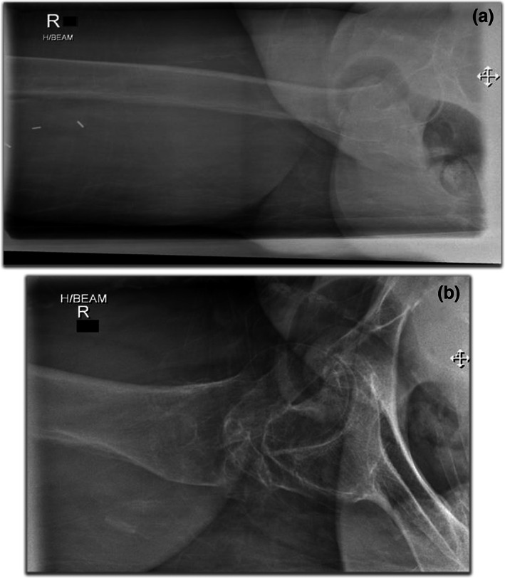
Proper collimation will only yield accurate results when radiographic position is performed correctly, and the beam correctly centred over the appropriate anatomy. A correctly collimated HBL should present the acetabulum, and the head and neck of femur, with the centring point midway between the anterior and posterior margins. The top image in Figure 3 demonstrates the effect of poor collimation practices. Image A of Figure 3 demonstrates an HBL hip with a measured dimension of 23 × 40 cm, measuring an EFOV of 920 cm2, 213% of the appropriate cassette size. The centring point is over the upper third of the femur. The result is a lack of detail over the femoral head and neck, and the image contrast is poor. The image was repeated minutes later (image B) utilising the same exposure factors, the EFOV is 432 cm2, collimated to the dimensions of the appropriate cassette size (18 × 24 cm). The opposite leg was also further abducted which reduced the soft tissue artefact overlying the neck of femur (NOF). There is a significant difference between the two images, with the repeated image demonstrating better detail of the femoral head and neck and improved image contrast. The centring point is also demonstrated to be over the NOF.
Traditionally, different size cassettes in film screen and computed radiography (CR) have served as the maximum field size required for different body parts. Collimation marks on a film‐screen image were the indicator that appropriate collimation had been applied. Since the advent of digital radiography (DR), image receptors as large as 43 cm x 43 cm are routinely used for imaging various body parts, from the chest and abdomen to single digits. The exploration of rejection rates of planar radiography is documented and found to be increasing 1 with associated dose ramifications. However, the study of radiographic collimation changes is sparse.
Collimationsynonyms
The x‐ray series of 359 patients who underwent imaging on the Siemens (Germany) Ysio x‐ray acquisition workstation machines in the emergency and general radiography departments over a twelve‐month period were reviewed. X‐rays were performed on a combination of fixed upright detectors measuring 43 cm x 43 cm and wireless detectors measuring 35 × 43 cm. All available studies for the projections chosen were reviewed, however, series containing a prosthesis such as a hip replacement were excluded from the study, as they would have required a larger cassette size from the reference standard. Reviewing the images on the acquisition workstation enabled electronic cropping to be removed, and the original collimation to be measured.
Image B depicting a properly collimated image (sent to PACS). Image A is the original, unmodified image; after removing the electronic mask the EFOV of the primary x‐ray beam (outlined in red) had a measured area of 27.5 cm x 32.3 cm corresponding to an area that is 205% (888.25 cm2) of the appropriate cassette size.
The authors would like to thank and acknowledge Justin Scott, Biostatician from the Metro South Biostatistics Clinic, Queensland Cyber Infrastructure Foundation Bioinformatics, Institute for Molecular Bioscience, The University of Queensland, Australia for his clear guidance, and Anne Bernard, Head of Biostatics, Queensland Cyber Infrastructure Foundation Facility for Advanced Bioinformatics, for providing the original statistical analysis.
Image A demonstrates collimation of 23 cm x 40 cm, corresponding to an area which is 213% (920cm2) of the appropriate cassette size, whilst the repeated image (image B) utilised collimation of 18 cm x 24 cm with identical exposure factors.
- Size : 88 mm X 137 mm X 30 mm - Operating Temperature - Display : 0 ~ 50 C - UV Sensor Probe : -30 ~ 85 C - Cable length : 5m (Standard) - Detection Range - UVV : 230 ~ 395 nm - UVA : 220 ~ 370 nm - UVB : 220 ~ 320 nm - UVC : 220 ~ 280 nm - UV Radiometer
Wrist radiograph with collimation margins visible creating a white or ‘silver’ border around the image indicating the image is the entire exposed field of view with no digital cropping.
Initially, it was hypothesised that the larger collimation field sizes demonstrated in this study was the result of ‘collimation creep’, whereby the use of electronic cropping was an avenue for less strict collimation. However, on reflection, one cannot rule out that radiographers were collimating larger than the cassette before the advent of digital radiography. A study by Zetterberg and Espeland comparing collimation practices pre and post the implementation of a DR saw an increase in the irradiated field size in digital images compared with analogue images. 12 There are still unanswered questions that may be lost the lost to the annals of time. The advantage of larger detector plates is that the EFOV size can be measured and audited. Contemporary radiography is at an exciting crossroads. Similar to reject analysis, radiography departments can now undergo collimation audits using the techniques utilised in this study. DR presents a unique opportunity to perform accurate and reproducible quality control audits within a department, the results of which could be utilised to focus targeted education to improve radiographic skills in weaker areas.
The study also did not assess the difference between the EFOV and the area of the FOV sent to PACS. Future studies could incorporate a greater range of projections to increase the amount of data available for analysis.


 Ms.Cici
 8618319014500