
Polytronix Privacy Glass: Privacy at the Flip of a Switch - switchable glass
Concavemirror examples
While the software primarily works with the GRBL protocol, it is designed to be modular and adaptable to other laser machine control systems. This allows for great flexibility and future support for other machine models. To help you get started, we have created a tutorial to assist you in preparing your file and sending it to your preferred machine. All testing has been done on the Sculpfun S9 and S30, but other machines can be used as well.
Convex mirror ray diagram
In this condition, we consider two rays parallel to the principal axis originating from the object. These rays, after reflection, converge and form an image at F, the principal focus of the mirror, in front of the mirror. The image thus formed is highly diminished, point size, real and inverted.
In Lasermagic, overscanning is controlled by a floating-point value overscanning. This value determines the additional distance the engraving head must travel after the laser has been turned off, before slowing down or changing direction.
In a spherical mirror, the distance of the object from its pole is called the object distance (u) and the distance of the image from the pole is called the image distance (v). As mentioned earlier, the distance of the principal focus from the pole is called the focal length (f).
This software allows the conversion of images into black and white (rasterization) for precise reproduction during laser engraving. Each pixel of the image is converted into a point or line engraved based on the desired intensity and contrast.
Overscanning solves this problem by ensuring that the laser head continues to move beyond the design limits before slowing down and changing direction. During this overshoot phase, the laser is already turned off. This allows the head to decelerate outside the engraving area, preventing speed variations from affecting the quality of the engraved edges.
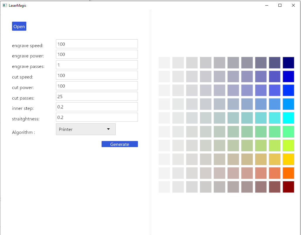
Then, fill in the values according to your needs and materials. You also have the option to choose between different algorithms.
The rays considered here are one parallel to the principal axis and the other passing through the centre of curvature of the mirror. This results in the formation of a highly enlarged image which is real and inverted at infinity.
It’s imperative to use colors from this range; otherwise, the path will not be considered when creating the .ngc file, which is used by the laser.
d) A ray incident obliquely to the principal axis, towards the point P (pole of the mirror), on the concave mirror, is reflected obliquely. The incident and reflected rays follow the laws of reflection at point P, making equal angles with the principal axis.
Mirrors concaveformula
Span Fill is designed to minimize laser movement time by optimizing paths over the engraving area. Unlike Printer Fill, which moves the laser across the entire length or width of the object, Span Fill uses shorter segments, engraving only the necessary areas without unnecessary movement.
Suppose you are engraving a design on wood at a speed of 150 mm/s and notice that the edges are slightly burned, even when the laser is set correctly. To improve engraving quality at the edges, you can adjust the overscanning.
Both laws of reflection are valid at every point on the curved surface of the mirror. The normal is drawn along the radius, i.e., it is drawn by joining the centre of curvature of the mirror to the point of incidence. The convergence of the rays after reflection is because the normal to the reflecting surface differs at each point on the mirror.
Air Assist is particularly useful for cutting thick or flammable materials, as well as for fine engraving where precision and cleanliness are crucial.
You can configure various power levels and different speeds depending on the material’s requirements and the desired outcome (e.g., deep engraving or light engraving).
There is a formation of different images in a concave mirror. It mainly depends on the distance between the object and the mirror. Concave mirrors form both real and virtual images. When the concave mirror is placed very close to the object, a virtual and magnified image is obtained, and if we increase the distance between the object and the mirror, the size of the image reduces and real images are formed. These real images can be projected on a screen. The focal point and the centre of curvature of the concave mirror lie in front of the mirror.
Rays emerging from a point meet at another point after reflection, and this point is called the image of the first point. The image is real if the rays converge to the point, and it is virtual if the rays do not meet it, but appear to diverge from a point when the rays are produced backwards. During image formation, we assume that the rays are paraxial, i.e., they are incident at points close to the pole P of the mirror and make small angles with the principal axis. For a concave mirror, we consider six positions of the object before the mirror.
Concavemirror image
Flood Fill works similarly to the fill algorithm found in graphic software, where the laser “fills” the area by following a path based on the shape and contours of objects. It usually starts from the center of an area and progressively fills it based on the borders.
b) A ray which is passing through the principal focus of a concave mirror, after reflection, will emerge parallel to the principal axis.
For example, if the speed is set to 100 mm/s and overscanning is set to 0.1, the engraving head will travel 100 mm/s × 0.1 = 10 mm beyond the laser stop before slowing down.
In Lasermagic, selecting the fill algorithm is managed via the algo-fill parameter. This parameter takes a text input, and you can select one of the three mentioned algorithms (printer, spanfill, floodfill) by simply specifying the algorithm name. Here’s how to use this parameter:
In this situation, we consider two different rays emerging from the object. One is parallel to the principal axis, and the other is directed towards the centre of curvature of the mirror. These rays, after reflection, form an image between the centre of curvature (C) and the focus (F). The image thus formed is diminished, real and inverted.
1. An object is found to be 5 cm in front of a concave mirror with a radius of curvature of 15 cm. Determine the position, nature, and magnification of the image in each case.
To adjust overscanning in your project, you need to set an appropriate value based on the speed and type of engraving you are performing. Here are the steps to use overscanning optimally:
To ensure Air Assist works properly, make sure your laser machine is equipped with a compressed air system or dedicated air pump that can provide a stable and sufficient airflow. This airflow must be directed at the laser head to be effective.
When you enable this option (air-assist = true), the software sends a command to trigger Air Assist during the engraving or cutting operation. This airflow is synchronized with the laser activity, meaning air is projected onto the work area only when the laser is active.
c) A ray passing through the centre of curvature of a concave mirror, after reflection, is reflected along the same path. The light rays come back along the same path because the incident rays fall on the mirror along the normal to the reflecting surface.
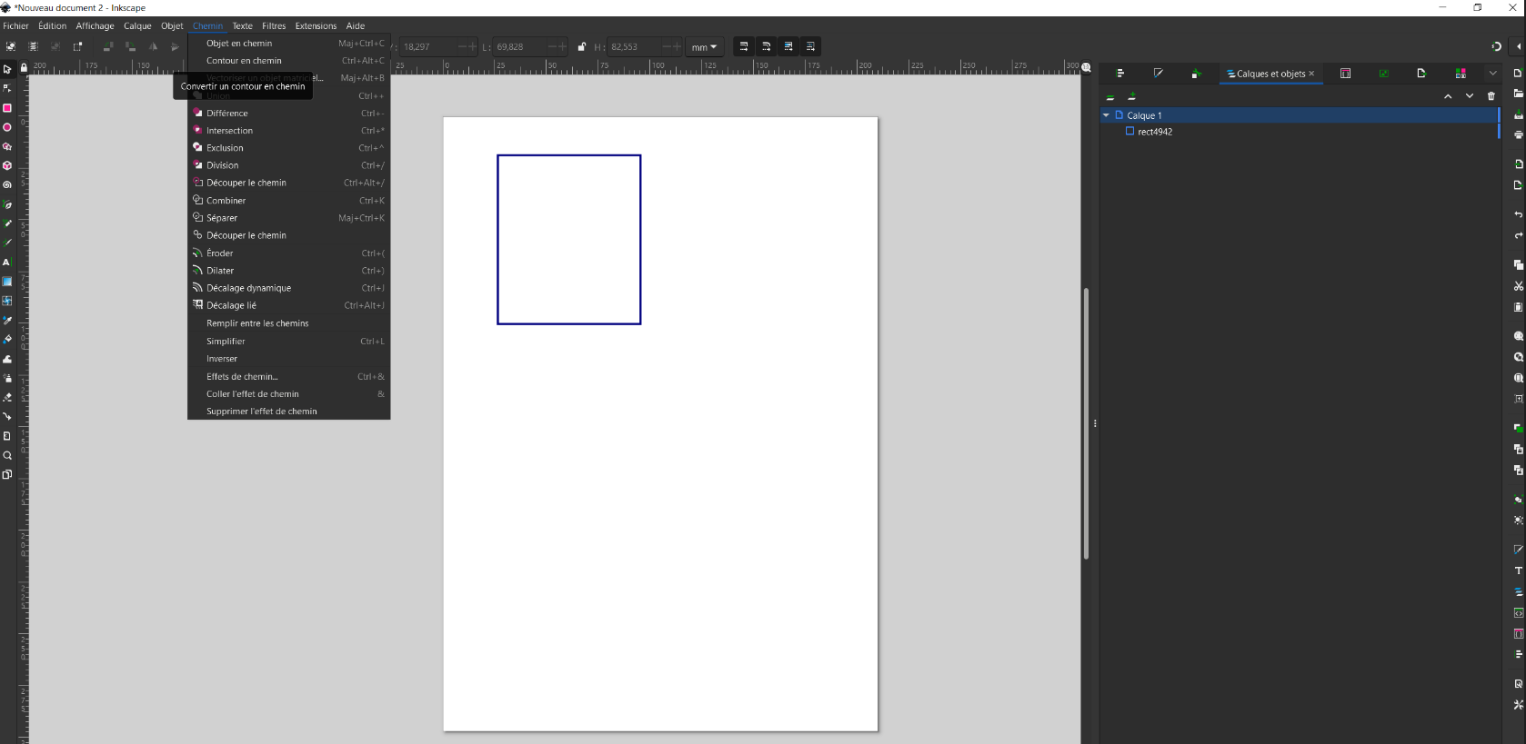
If the elements don’t touch, they should remain as independent paths in your drawing. If you use the “Union” function to make them into a single path, the slicer may have problems calculating the path to take, making the process longer. Use the “Split path” option in the path menu to extract paths that do not touch.
After generating your G-code file with LaserMagic, you need to transfer this file to your CNC machine. We recommend using Universal Gcode Sender (UGS), a popular open-source software for sending G-code to machines controlled by GRBL.
The rays considered here are one going parallel to the principal axis and the other passing through the centre of curvature of the mirror. The image formed here is virtual and erect, and it is larger than the object.
Once the window is open, by selecting the group of your paths, you’ll find in the XML editor the different parameters for laser processing.
2. An object, 4 cm in size, is placed at 25 cm in front of a concave mirror of focal length 15 cm. At what distance from the mirror should a screen be placed to obtain a sharp image? Determine the nature and the size of the image.
Images are natively supported by the software, without requiring any additional action from the user. The image is automatically converted into a suitable rendering for engraving using rasterization, which allows for an accurate black-and-white representation of the original.
You’ll need to download the latest releases of the tool from here. For beginners we advise to begin with inkscape plugin method
In Lasermagic, the algo-fill parameter allows you to choose from several fill algorithms by entering specific text (such as printer, spanfill, or floodfill), each with unique characteristics.
Fill (or hatching) is a method used in laser engraving to cover solid areas of a design or image with engraved lines. Unlike cutting, where the laser follows outlines to cut material, laser engraving involves filling entire areas with an engraved pattern, which requires a strategy for moving the laser efficiently across the surface. The goal of fill is to maximize efficiency (reduce engraving time) while maintaining engraving quality (uniform coverage on solid surfaces).
This means that the laser head will continue to move 15 mm beyond each edge before starting to decelerate. Since the laser is off during this overshoot, the edges will be cleaner and without overheating.
The figure shows two rays emerging from the object. These rays, after reflection, form an image A’B’. From the geometry of ray diagrams, the two right-angled triangles ABF and MPF are similar. This is because, for paraxial rays, the line MP can be considered to be a straight line perpendicular to CP. Therefore,
The Air Assist feature blows air during engraving or cutting, helping to reduce burns and residue buildup on the material. The directed airflow also removes debris and improves the quality of cutting or engraving, which is especially useful for sensitive materials.
The color range used is already integrated into Inkscape, so you don’t need to import it. However, if you haven’t already integrated it, you can retrieve the palette here:
Ray diagrams are necessary for understanding the formation of an image by a concave mirror. For constructing ray diagrams and for a better understanding of image formation, we should consider at least two incident rays coming from the object. The intersection of these two rays after reflection gives the position of the image of the object. For a concave mirror, any of the following four ray diagrams can be used for locating the image formed:
The preview image mode allows you to visualize a simulation of the laser path before performing the actual engraving. By enabling this option, you’ll see a preview of the final output on a wood-like representation, helping you confirm that the path aligns with your expectations. This mode is useful for simulating both engraving and cutting results.
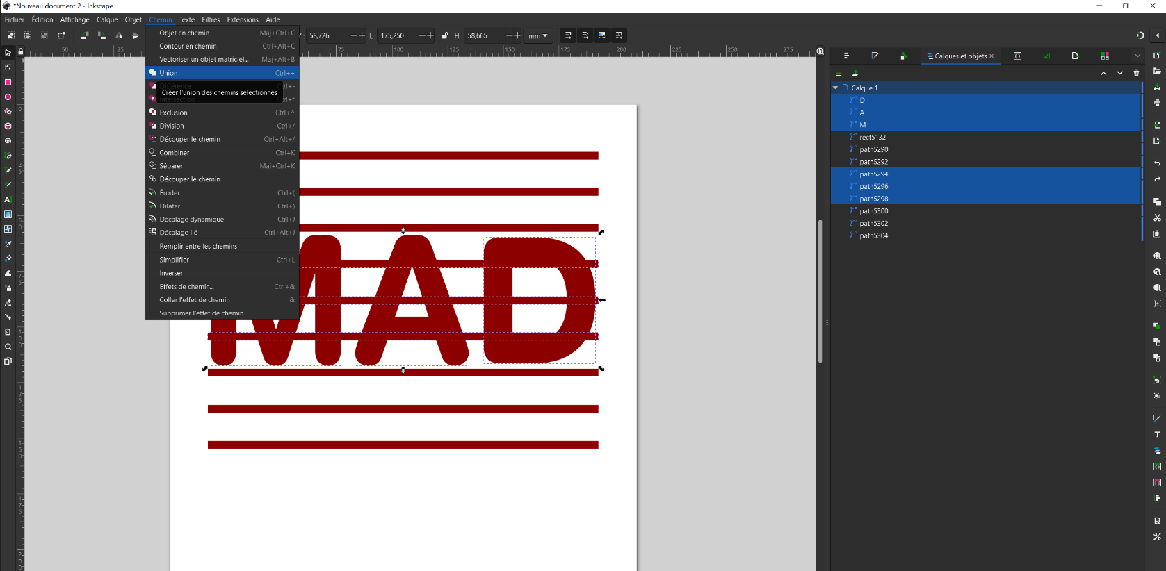
When creating your drawings, remember to simplify and make them as clean as possible (fewest independent “paths” possible). A simple tip for this is to use the “Union” option in the “Path” menu to remove all intersecting paths, preventing the laser from passing over the same spot multiple times.
Consider a ray parallel to the principal axis striking the concave mirror at a point M on its reflecting surface. Then CM will be perpendicular to the mirror at point M. Let θ be the angle of incidence, and MD be the perpendicular from M to the principal axis.
Concaveand convex mirror
Flammable materials: Air Assist is particularly recommended for materials like wood, leather, paper, and some plastics, where engraving or cutting residues can easily ignite or burn. Detailed engraving: If you’re working on projects requiring high precision (such as fine engraving on sensitive surfaces), Air Assist helps keep the engraving area clean and free of debris that could interfere with the laser beam. Cutting thick materials: During the cutting of thick materials, Air Assist helps clear accumulated debris from the cut, allowing the laser to pass through more effectively and produce a cleaner cut.
In this lesson, we will discuss image formation in concave mirrors. However, before we delve into the topic, let us quickly recall what a concave mirror is and the principles behind its working. A concave mirror is a type of spherical mirror in which the reflecting surface is the inner-curved surface of the sphere, i.e., in this type of mirror, the reflecting surface seems to be away from the incident light source. Because of their shape, the incident light is reflected inwards (converged); thus, they are also called converging mirrors and are used for focusing light.
After vectorizing your image, the different parts of your image are combined into a single path. However, as mentioned earlier, when our shapes are separate, for the sake of efficient path calculation, it’s better for each shape to be an independent path.
The tool allows vectorized elements to be converted into commands for the machine, whether for cutting or engraving. It also supports advanced options to optimize the quality and precision of laser work.
Here, the two rays emerging from the object are one parallel to the principal axis and the other passing through the focus of the mirror. These rays, after reflection, form an image at point C. The image formed has the same size as that of the object, and it is real and inverted.
For deriving the relevant formulas for reflection by spherical mirrors, there is a standard sign convention for measuring distances. The normally used convention is the Cartesian sign convention. According to this convention, all the distances are measured from the pole of the mirror, i.e., the pole (P) of the mirror is assumed as the origin. The principal axis of the mirror is taken as the x-axis of the coordinate system. The conventions are as given below:
Set the fill algorithm: Adjust the algo-fill parameter based on the type of design you’re engraving and the requirements of your project. For example, for a large and regular area, you can use Printer Fill (algo-fill = printer). For complex designs, opt for Span Fill or Flood Fill. Test and optimize: It’s recommended to experiment with the different algorithms to determine which offers the best results based on the complexity of your design, the material used, and the available engraving time. Each algorithm has advantages in specific situations, and the optimal choice often depends on the project type. Practical example If you’re engraving a simple logo on a wooden plaque, you might choose Printer Fill to ensure uniform engraving across the entire surface. If you’re working on a detailed design with irregular shapes, such as a complex vector image, using Flood Fill or Span Fill will reduce engraving time while maintaining high precision in the engraved areas.
Here, the two rays considered are one parallel to the principal axis and the other passing through the principal focus of the concave mirror. The image is formed beyond C. The image is larger compared to the size of the object, and it is real and inverted.
In Lasermagic, activating Air Assist is simple. It is a binary parameter (true/false) that can be controlled through the air-assist option.
Description: The Printer Fill works in a linear fashion, engraving line by line, similar to how an inkjet printer operates. The laser moves from side to side across the engraving area, following horizontal or vertical lines, and systematically engraves the surface.
When you want to generate your gcode file you can go to Extension -> Export -> Export Laser or save your file and use the cli or the ui as explain above.
Difference betweenconcaveand convex mirror
For this documentation, we will be using the open-source software Inkscape. There are other vector drawing software options available, such as Illustrator.
Concaveand convex mirror examples
The Span fill algorithm should be slightly more efficient for file generation, but it’s advisable to experiment with the different outputs to choose what you prefer.
The current method used for image rendering is rasterization, and dithering. This technique will offer enhanced rendering, especially on less uniform materials, providing better gradation management and a visually more pleasing result.
Overscanning is a technique that disables the laser just before the engraving head slows down at the edges of the image or path. This prevents excessive burning and overly defined edges, ensuring a cleaner and more uniform result.
This is an open-source and free software designed to simplify the preparation of files for laser engraving or cutting machines. Primarily oriented towards communication with machines running on the GRBL protocol, it can be easily extended to support other laser controller models. To download the latest version of the software, you can go there
If the color you’ve chosen isn’t in the “Laser” color range, you’ll receive an error message on that path when converting to .ngc with Magic Laser.
When preview image mode is enabled, the rendered preview can be exported in PNG format for later reference or sharing. The exported files are named according to the type of simulation:
To connect to your laser machine, select the correct port, set the baud rate (usually 115200), and ensure the Firmware is set to GRBL. Then, connect by clicking the following icon:
A negative sign for the value of magnification indicates that the image is real, and a positive sign indicates that the image is virtual.
Mirrors concavevsconcave
Air Assist is a feature used in laser engraving and cutting to improve the quality of work and protect the material. This feature works by projecting a constant high-pressure air stream directly onto the area where the laser is engraving or cutting.
Overscanning is a technique used in laser engraving systems to avoid excessive burns and imperfections on the edges of engraved designs. When a laser engraving head stops or changes direction at the end of a pass, there can be an accumulation of energy at those points, creating overburnt areas or overly defined edges.


 Ms.Cici
 8618319014500