
Optics and Microscope Accessories | Olympus LS - microscope optics
Modulation Transfer Function (MTF) is a fundamental measure of imaging system sharpness. It is introduced in Sharpness and discussed further in Sharpening. MTF ...
Bigger pixels have benefits to sensitivity. Indirectly, they also have benefits on the total time it takes to get the information out to the computer. Total readout time is dependent on camera architecture, with CMOS being faster than CCD, but also on the total number of pixels in the camera. In general, a camera with bigger but fewer pixels will be ready for the next exposure faster that a camera with more, smaller pixels.
The interaction of light with matter in a linear regime allows the absorption or simultaneous emission of light precisely matching the difference in energy levels of the interacting electrons.
Thus lower energy states will have more molecules in them than will higher (excited) energy states. Therefore, the Stokes spectrum will be more intense than the anti-Stokes spectrum.
Microscope objectives contain lenses but are not as simple as the lenses seen in Fig.2, making them complex lenses (Fig.3A). While the overall effect can be magnification, these lenses are carefully designed to control a variety of aspects of lenses, such as working distance, and the ability to correct problems such as aberrations. Objectives are characterized by two factors: magnification and numerical aperture (NA). Objective magnification ranges from 2x to 100x (and is combined with the eyepiece magnification), magnifying the sample 2-fold to 100-fold respectively (Fig.3B). NA is related to the focal length of the lens, namely what angle light exits/enters the objective, as this affects the resolution (Fig.3C, read our app note on resolution and NA for more). See Fig.3 for more information.
Eyepiecelensmicroscope
Connect a cable from the camera's USB-C port to a PC running Windows or Linux. Macs are not supported at this time, although USB passthrough to a VM may be ...
Mar 1, 2024 — Cantilever beam with uniform distributed load. The load w is distributed throughout the cantilever span, having constant magnitude and direction ...
Magnifier · Magnifying glass, an optical device for magnification · Screen magnifier, software that magnifies part of a computer screen · Magnifier (iOS), a ...
In 1922, Indian physicist Chandrasekhara Venkata Raman published his work on the "Molecular Diffraction of Light," the first of a series of investigations with his collaborators which ultimately led to his discovery (on 28 February 1928) of the radiation effect which bears his name. The Raman effect was first reported by C. V. Raman and K. S. Krishnan, and independently by Grigory Landsberg and Leonid Mandelstam, in 1928. Raman received the Nobel Prize in 1930 for his work on the scattering of light. In 1998[2] the Raman Effect was designated an ACS National Historical Chemical Landmark in recognition of its significance as a tool for analyzing the composition of liquids, gases, and solids.[3]
Buy Celestron UV/Infrared Cutoff Filter (1.25") Review Celestron null.
Two illumination methods, critical or Köhler, are commonly used to illuminate the sample in microscopy. The primary difference is whether they copy the structure (critical) or scramble the structure (Köhler) of the illumination source at the sample. As Köhler illumination is more frequently used, it will be covered in this article.
Raman-active vibrations/rotations can be identified by using almost any textbook that treats quantum mechanics or group theory for chemistry. Then, Raman-active modes can be found for molecules or crystals that show symmetry by using the appropriate character table for that symmetry group.
Function ofdiopter adjustmentin microscope
The field stop limits the area that can be imaged. This can't be bigger than the diameter of the tube lens. At best, the area imaged is the diameter of this lens divided by the magnification. If the internal lens has a diameter of 25 mm and the magnification is 100x, one should see a circle with a diameter of 250 µm of the sample. Things suc h as light modifying elements, or the detector itself, can easily reduce the field of view that is collected.
There are all kinds of cameras that can be used with a microscope. Key experimental considerations are the sensitivity, resolution, field of view and speed of a camera. For a detailed explanation, see our articles on these subjects.
Function ofnosepiecein microscope
Figure 2: Convex vs concave lenses. A convex lens is thicker at the center than the edge and will focus a beam of light to a point a certain distance in front of the lens (the focal length). A concave lens is the opposite, being thicker at the edge than the center and spreading out a beam of light. Microscopes use convex lenses in order to focus light. Image from http://clubsciencekrl.blogspot.com/.
Raman spectroscopy is also used in combustion diagnostics. Being a completely non-intrusive technique, it permits the detection of the major species and temperature distribution inside combustors and in flames without any perturbation of the (mainly fluid dynamic and reactive) processes examined.
Figure 5: Köhler illumination optics. The lamp has a zig-zag filament on the left-hand housing, and the sample is to the right. Working from left to right, light from the lamp is imaged to a position 1F from the principal plane of the condenser. Light with structure entering the condenser is scrambled upon delivery to the sample. The field stop provides control of the area in the sample that is illuminated. The aperture stop controls the range of angles, and the power, of the illumination. The light path from a central point of the filament at left to the sample at right is highlighted in orange. Derived from Biomedical Engineering Dept at Boston University.
By combining the properties of SP and LP filters, bandpass (BP) filters were created. A SP 550 nm filter combined with a LP 500 nm filter would transmit light only between 500-550 nm. BP filters are usually described by their center wavelength and the allowed wavelengths to either side. A hypothetical SP550, LP500 filter combination is commonly referred to as BP 525d25, a BP centered at 525 nm with 25 nm transmission permitted to either side (Reichman, 2017).
Figure 3: On microscope objective lenses. A) An example of the location of lenses in an objective cross-section, making this a complex lens. B) Different Nikon Super Fluor objectives, ranging from 10x to 40x. The red boxes show the magnification / NA of the lens, with the air 40x having an NA of 0.90 and the oil-immersion 40x having an NA of 1.30, showing the effect of the imaging medium on the NA (the denser the better). C) How different NA affects the illumination of the sample, the higher the NA the greater the angle of light from the objective, and the greater the maximum resolution.
The Raman effect corresponds, in perturbation theory, to the absorption and subsequent emission of a photon via an intermediate electron state, having a virtual energy level (see also: Feynman diagram). There are three possibilities:
A Raman transition from one state to another, and therefore a Raman shift, can be activated optically only in the presence of non-zero polarizability derivative with respect to the normal coordinate (that is, the vibration or rotation):
4. Reichman, J. 2017 Handbook of Optical Filters for Fluorescence Microscopy. Chroma Technology Company Bellows Falls, Vermont 05101-3119 (https://www.chroma.com/sites/default/files/HandbookofOpticalFilters.pdf)
The parts of the microscope discussed here work in concert to send light to the sample and take the light from the sample and magnify it up to the detector for collection. Aperture stops, usually in the objective, limit the microscope resolution. Field stops limit the area illuminated or detected. Components such as objectives, light sources, filters, and cameras all must be considered to get the best possible image.
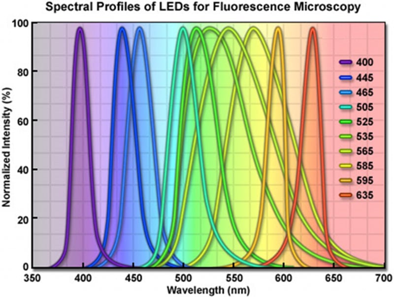
Figure 6: Normalized intensity versus wavelength plot of LEDs useful for fluorescence microscopy. Taken from http://www.fluorescencemicroscopy.it/en/illumination.html
Filters are commonly referred by the nature of their transmission, and the wavelength where they switch from transmission to reflection, as illustrated in Fig.8. A 500 nm short pass (SP) filter would transmit light bluer than 500 nm and reflect light redder than 500 nm. In contrast, a 500 nm long-pass (LP) filter will transmit light longer than 500 nm, reflecting light of shorter wavelengths.
Most microscopes have optical exit ports with a diameter of around 18-25 mm. Using no magnification (1x objective), the image would, therefore, cover 18-25 mm of the sample. Given the fixed size of the image, camera sensors with diagonal dimensions greater than the microscope camera port would have pixels with no light falling on them. Therefore, it is important to match the field of view of the camera with the maximum field of view of the microscope.
There are a variety of lamps, light-emitting diodes (LEDs) and lasers that can be used to illuminate the sample in the microscope. Typical lamps used for illumination include:
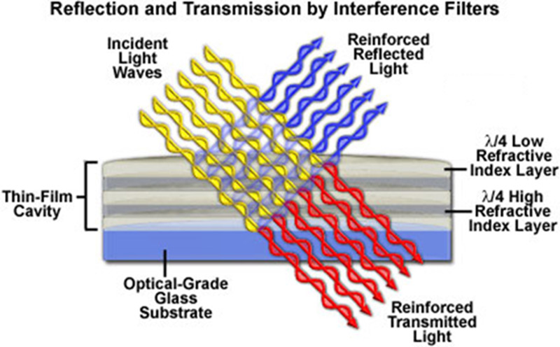
Figure 7: Modern color-selecting interference filter. The various layers on top of the glass substrate acting in total reflect blue light while allowing transmission of the red light. Taken from http://zeiss-campus.magnet.fsu.edu/articles/lightsources/leds.html
What iseyepiece in microscope
Mar 23, 2021 — This type of microscope features a built-in source of illumination (usually in the base of the unit) that brightens the area underneath the lens ...
LED light sources are powerful enough to compete with xenon and mercury/metal halide lamps as illumination sources for fluorescence imaging. Each LED has a unique color, so LED broad band sources are derived from arrays of multiple individual diodes of relatively narrow spectra. LED sources have lifetimes of 10,000+ hours of use and are highly energy-efficient, making them very economical over long term use. They can be turned on and off quickly, over nanoseconds, making them useful for experiments requiring tight control of illumination. The spectral distribution of an example LED light source is illustrated in Fig.6.
The Raman effect differs from the process of fluorescence. For the latter, the incident light is completely absorbed and the system is transferred to an excited state from which it can go to various lower states only after a certain resonance lifetime. The result of both processes is essentially the same: A photon with the frequency different from that of the incident photon is produced and the molecule is brought to a higher or lower energy level. But the major difference is that the Raman effect can take place for any frequency of the incident light. In contrast to the fluorescence effect, the Raman effect is therefore not a resonant effect.
Filters are optical components that can transmit certain wavelengths of light while reflecting others. Color selection is critical for fluorescence imaging. An example of optical filtering is shown in Fig.7.
6. Spring, K.R., Parry-Hill, M., Burdett, C.A., Sutton, R. T., Fellers, T.J. and Davidson, M.W. Laser Fundamentals in the Olympus Microscopy Primer website (https://www.olympus-lifescience.com/en/microscope-resource/primer/lightandcolor/laserhome/)
In the fluorescence microscope, a combination of excitation BP filter, a LP dichroic filter and an emission BP filter are organized into a cube holder to provide high-intensity excitation light to the sample and efficiently isolate emission light before steering it off to the camera.
Function ofbody tubein microscope
A camera pixel is the individual light-measuring unit in the camera, and the camera's sensor has arrays of pixels to measure the light across the field of view. A camera might have as few as 128×128 pixels, or as many 5000×3000 (15 million pixels, or 15 megapixels) or more. Since microscope camera ports commonly have the same approximate size, cameras with larger pixel arrays usually have smaller individual pixels.
Raman amplification can be obtained by using Stimulated Raman Scattering (SRS), which actually is a combination between a Raman process with stimulated emission. It is interesting for application in telecommunication fibers to amplify inside the standard material with low noise for the amplification process. However, the process requires significant power and thus imposes more stringent limits on the material. The amplification band can be up to 100 nm broad, depending on the availability of allowed photon states.
These differences in energy are measured by subtracting the energy of the mono-energetic laser light from the energy of the scattered photons. The absolute value, however, doesn't depend on the process (Stokes or anti-Stokes scattering), because only the energy of the different vibrational levels is of importance. Therefore, the Raman spectrum is symmetric relative to the Rayleigh band. In addition, the intensities of the Raman bands are only dependent on the number of molecules occupying the different vibrational states, when the process began. If the sample is in thermal equilibrium, the relative numbers of molecules in states of different energy will be given by the Boltzmann distribution:
Function ofobjective lensin microscope
The focal length of a microscope objective lens needs to be very small, as the objective is often very close to the sample. Typically, the higher the magnification, the closer the objective needs to be.
Figure 8: Transmittance versus wavelength for various filter types. In the LP example, red light would pass through and blue light would be reflected. In the SP example, blue light would pass and red light reflected. In the BP example, both blue and red light is reflected while green light is transmitted. Taken from Basic Aspects of Light Filters Molecular Expressions Optical Microscopy Primer https://micro.magnet.fsu.edu/primer/lightandcolor/filtersintro.html
The output of most microscopes is an image about 2 cm across, so this is typically magnified again in order to fill the field of view of the eyes. Eyepieces, another magnification system, give between 10x to 30x magnification on top of that provided by the objective and microscope. In combination with the lens in the eye, this magnifies the image to the retina at a useful scale, so that the human eye may resolve and observe objects even as small as cells (~10 µm).
Jan 19, 2021 — Description ... Hyperspectral data presents a unique opportunity to characterize specific vegetation types and biogeochemical processes across the ...
Function ofarmin microscope
The useful life of each of these sources varies between a few hundred hours for mercury arc lamps, to 1000-2000 hours for mercury/metal halide and halogen lamps.
5. Spring, K.R., Parry-Hill, M. & Davidson, M.W. Geometrical Construction of Ray Diagrams in the Olympus Microscopy Primer website (https://www.olympus-lifescience.com/en/microscope-resource/primer/java/components/characteristicrays/)
Answer and Explanation: 1. The lens in the eyepiece of a microscope is called an ocular lens; it magnifies the image. The amount of magnification depends, but ...
Pixel size is key to being able to image with the full information content provided by the optics. Camera pixels are square and usually 3-24 µm along the edge. Generally speaking, cameras with smaller pixels allow for higher resolution imaging whereas cameras with larger pixels have a larger surface area for photon collection making them more sensitive.
Stimulated Raman transitions are also widely used for manipulating a trapped ion's energy levels, and thus basis qubit states.
For high intensity CW (continuous wave) lasers, SRS can be used to produce broad bandwidth spectra. This process can also be seen as a special case of four wave mixing, where the frequencies of the two incident photons are equal and the emitted spectra are found in two bands separated from the incident light by the phonon energies. The initial Raman spectrum is built up with spontaneous emission and is amplified later on. At high pumping levels in long fibers, higher order Raman spectra can be generated by using the Raman spectrum as a new starting point, thereby building a chain of new spectra with decreasing amplitude. The disadvantage of intrinsic noise due to the initial spontaneous process can be overcome by seeding a spectrum at the beginning, or even using a feedback loop like in a resonator to stabilize the process. Since this technology easily fits into the fast evolving fiber laser field and there is demand for transversal coherent high intensity light sources (i.e. broadband telecommunication, imaging applications), Raman amplification and spectrum generation might be widely used in the near future.
Raman spectroscopy employs the Raman effect for materials analysis. The frequency of light scattered from a molecule may be changed based on the structural characteristics of the molecular bonds. A monochromatic light source (laser) is required for illumination, and a spectrogram of the scattered light then shows the deviations caused by state changes in the molecule.
A lens is an optical device that can refract light. The refraction depends on the shape of a lens, which is typically convex or concave. For the purposes of microscopy, convex lenses are used for their ability to focus light at a single point. This is how the human eye works, with the convex biological lens focusing light on the back of your eye where rod and cone cells can detect it. Microscopes borrowed this idea, using convex lenses to focus light towards a point that is f distance away from the lens. This distance is known as the focal length of the lens and depends on the shape. Lens shapes can be seen in Fig.2. It should be noted that these lenses are symmetrical and will have the same effect on light from either direction.
2. Davidson, M.W. Koehler Illumination in the Zeiss Basic Resources website (https://w ww.zeiss.com/microscopy/us/solutions/reference/basic-microscopy/koehler-illumination.html)
When light is scattered from an atom or molecule, most photons are elastically scattered (Rayleigh scattering). The scattered photons have the same energy (frequency) and wavelength as the incident photons. However, a small fraction of the scattered light (approximately 1 in 1 million photons) is scattered by an excitation, with the scattered photons having a frequency different from, and usually lower than, the frequency of the incident photons.[1] In a gas, Raman scattering can occur with a change in vibrational, rotational or electronic energy of a molecule (see energy level). Chemists are concerned primarily with the vibrational Raman effect.
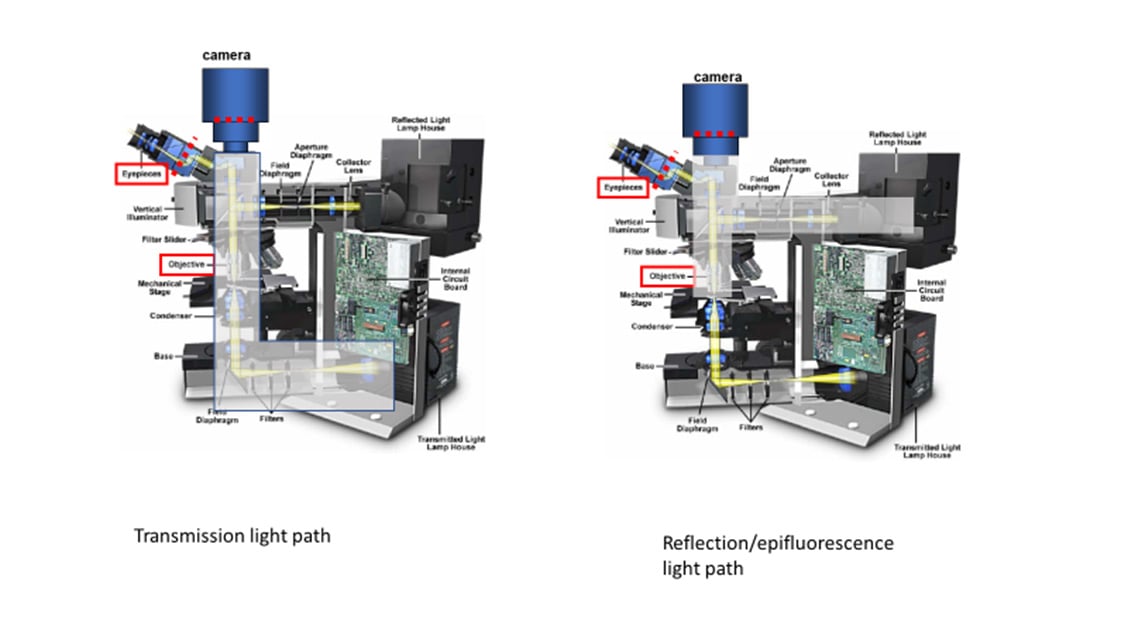
Figure 4: Transmission/trans-fluorescence and reflection/epi-fluorescence microscopy light paths in a model microscope. The gray area indicates the light paths involved for each mode. Derived from an image of a microscope on the Olympus Microscopy Primer and modified by the author.
Partsof microscopeand itsfunction
Figure 1: Cut-away image of a modern microscope. There are two independent illumination pathways; 1) Epi-illumination reflected through the objective lens to illuminate the sample from above, 2) Trans-illumination focused by a separate condenser lens to illuminate the sample along the imaging axis of the microscope. There is a single imaging pathway for light, from the sample, through the objective and tube lenses and into the detector/camera or eyepiece. Derived from an image of a microscope on the Olympus Microscopy Primer and modified by the author.
Sep 3, 2021 — Meanwhile, lenses with short focal lengths have a larger depth of field, which enables them to get a wider range of elements in focus.
Lasers provide light with highly specific wavelengths. For example, the light generated by a helium-neon (HeNe) laser has a color of 632.8 nm. Unlike the other light sources discussed here, lasers provide coherent light. Coherence indicates that the light is highly structured, with all the peaks and troughs of the light wave occurring at the same time and place. Coherence is necessary when focusing light to a diffraction-limited point, but also complicates widefield illumination due to its tendency for positive and negative interference. This self-interference can often be detected as a speckle pattern in an expanded laser beam.
The aperture stop is the part of the imaging system that limits the range of angles of light the lens can collect from the sample. This range of angles defines the lens NA and therefore the system resolution, the ability to detect two objects as different. Most microscope objectives are designed such that the aperture stop is the Objective Rear Aperture, as seen in Fig.3A. This ensures that the objective defines the system resolution and that the resolution is the same across the entire field of view.
Various microscopy methods detect specific interactions between light and the sample. Methods that image scattered or absorbed light focus illumination light to the sample using a separate illumination lens and imaging objective. The focusing illumination lens is referred to as a condenser, with its own properties of working distance, NA, etc.
Putting the illumination source close to the sample limits control of light intensity and illumination field of view. Köhler imaged the light source to a focal length from the condenser lens, as illustrated in Fig.5. This provides control of the field of illumination, with a field stop in the middle of the imaging component and an aperture stop 1f away from the condenser. The aperture stop is a highly significant aspect of the design; allowing easy control of the light power to the sample. These stops usually have levers allowing the user to manually adjust the illumination area (field stop) and power (aperture stop) being delivered to the sample.
These components are responsible for the magnification, resolution, and field of view inherent in the microscope. In this article, the details of microscope components and anatomy are explained in relation to how they contribute to providing the best possible image. In order to see the arrangement of these components, see Fig.1.
There are always constraints to the area to be imaged and the detailed information a microscope provides. There are physical blocks in the light path, typically named stops, diaphragms, or apertures. Here, the term stop will be used. For the imaging path, they may or may not be adjustable by the user, but as discussed later, the same concepts apply to the illumination optics.
This process involves taking the Cylinder value from your prescription and converting it into diopters using a similar formula. Once you have your new ...
The distortion of a molecule in an electric field, and therefore the vibrational Raman cross section, is determined by its polarizability.
Köhler invented a focusable illumination system that allowed control of the field size, the power and the angle of illumination while scrambling the structure of the light source projected on the sample. He took advantage of the property of a lens to convert the lateral structure into parallel rays to do this. Putting an illumination source at the focal point of the lens transforms the output into uniform light rays on the other side, scrambling any structure inherent in the source. Multiple points emitting from the light source all end up scrambled and traveling in parallel rays after exiting the lens
At its core, a typical microscope is essentially a box designed to hold two lenses in precise positions so that light can be accurately magnified from the sample to the detector. The first of these two lenses is the objective lens, which is located close to the sample, moves when the focus dial is turned and has useful information such as magnification written on its side. The second is commonly referred to as the tube/collector lens, which is buried deep within the body of the microscope and rarely seen.
Fluorescence microscopy uses reflection or epi-fluorescence geometry, where the objective serves as both the illumination condenser and the imaging lens. The illumination light is passed through the objective and the detected light is passed backward through the objective and split off to a camera or eyepiece. One benefit of this approach is that light that doesn't interact with the sample travels away from the detector, maximizing separation of illumination light from fluorescent emission. The transmission and epi-fluorescence light paths are illustrated in Figure 4.
3. Parry-Hill, M.J., Vogt, K.M, Griffin J.D., and Davidson, M.W. Matching Camera to Microscope Resolution in the MicroscopyU website (https://www.microscopyu.com/tutorials/matching-camera-to-microscope-resolution)


 Ms.Cici
 8618319014500