
Optical Links And Tracking For Free-Space ... - free-space optical communication
High powerobjective lens
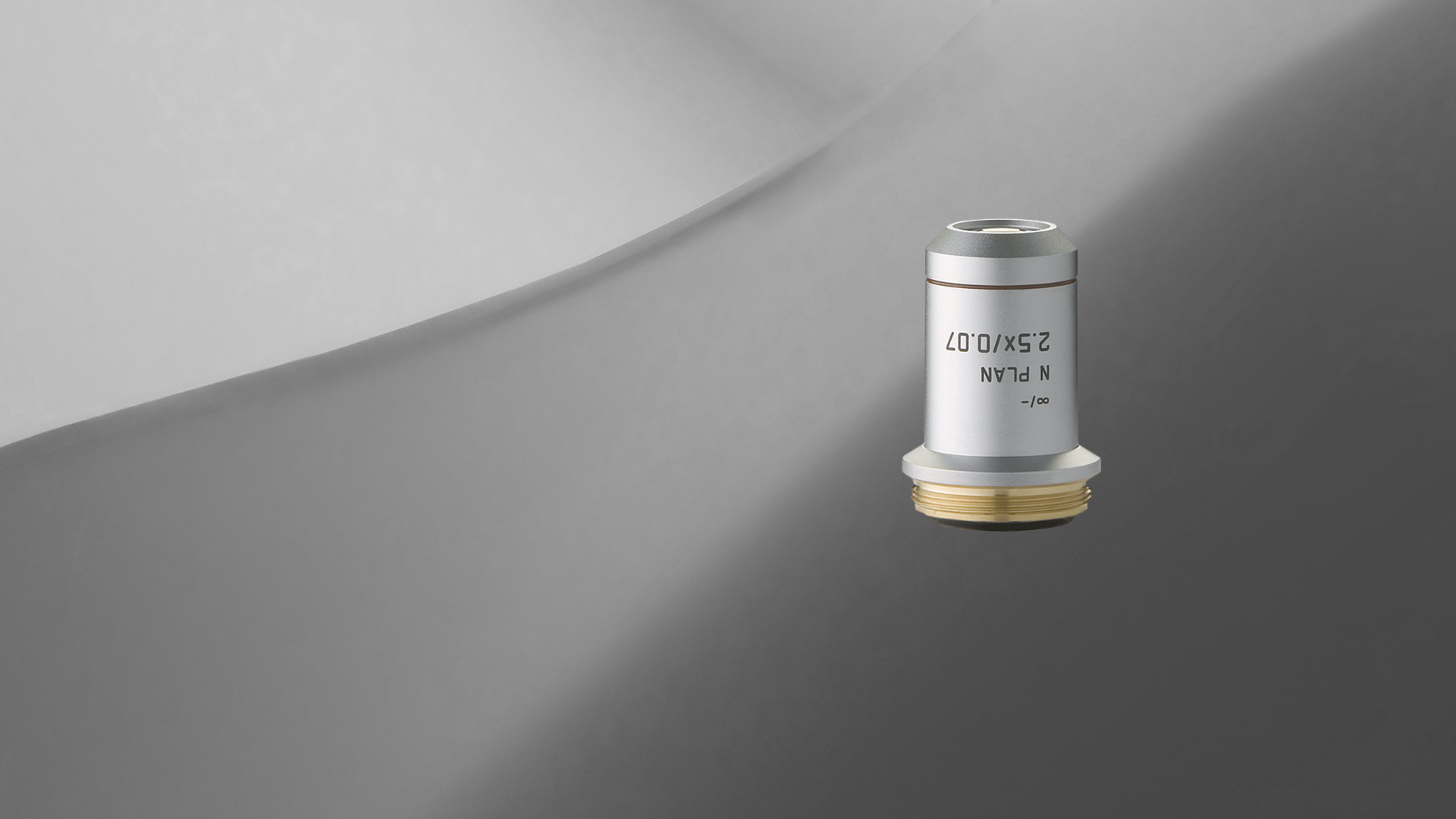
Leica microscope objective lenses are designed and made by our optics specialists to have the highest performance with a minimum of aberrations. The objectives help to deliver superior microscope image quality for many applications, such as life science and materials research, industrial quality control and failure analysis, and medical and surgical imaging.
Retroreflectors are now crucial for night-driving and are seen on all major roads. They are on the tail-lights of vehicles, safety barriers, traffic signs, and the painted stripes that separate lanes of traffic.
Leica achromats are powerful objectives for standard applications in the visual spectral range, offering field flatness (OFN) up to 25 mm. The absolute value of the focus differences between red wavelength and blue wavelength (2 colors) is ≤ 2x depth of field of the objective.

What isobjective lens in microscope
A simple retroreflector can be made from 3 mirrors arranged to form a corner of a cube. Instructions are available online: see reference to Make magazine below (don’t forget: never look directly at a laser beam or its reflection).
This works only in two dimensions: when the light beam is in a plane orthogonal to the two mirrors, it remains in this plane. In general, we need three mirrors to ensure the beam can return in the direction whence it came.
Stage clipsmicroscope function
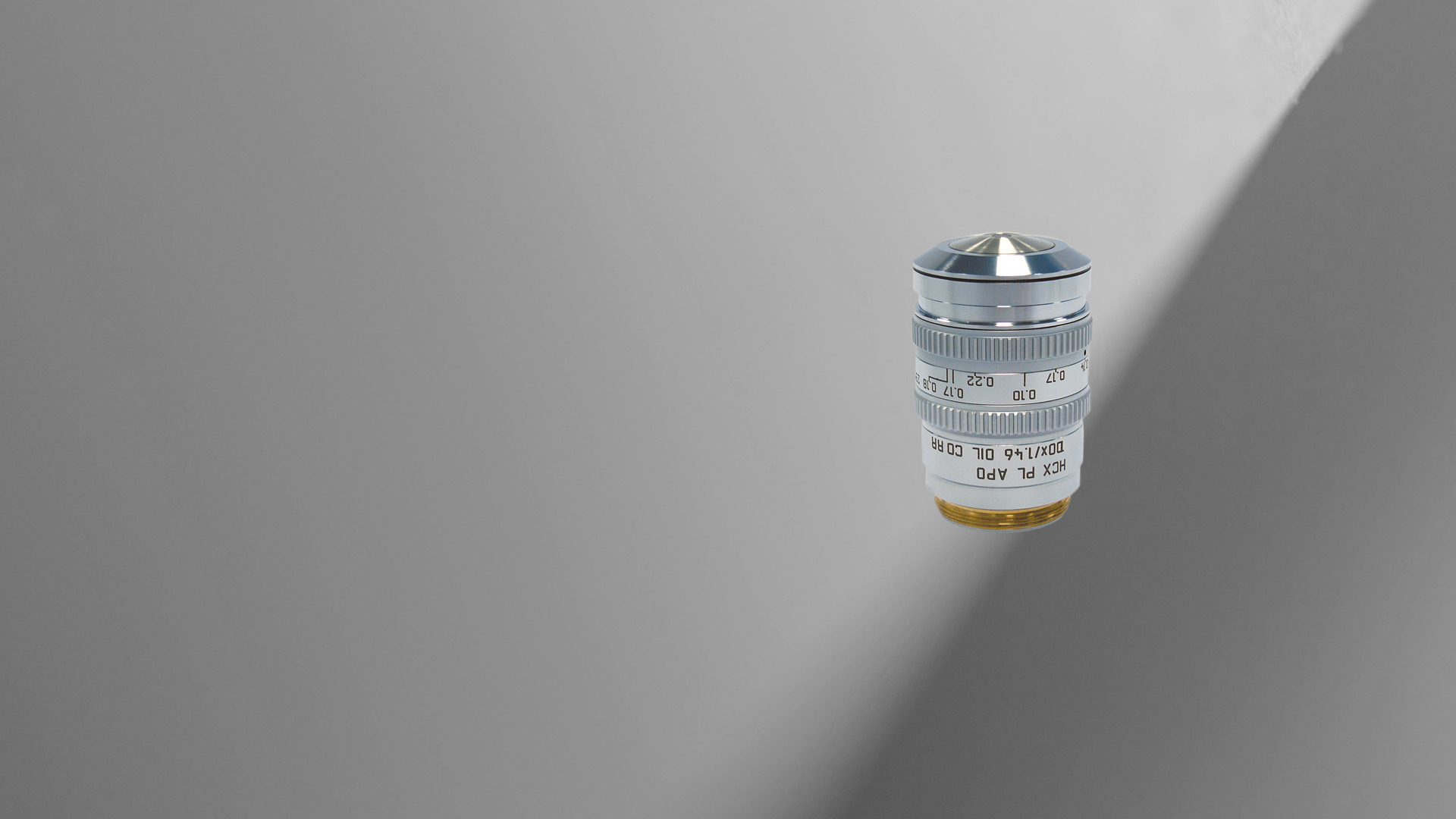
All Leica objectives are marked with codes and labels. These identify the objective, its most important optical performance properties, and the main applications it can be used for. For more information, refer to: Labeling of Objectives
Leica apochromats are objectives for applications with highest specifications in the visual range and beyond, offering field flatness up to 25 mm. The absolute values of the focus differences for the red wavelength and the blue wavelength to green wavelength (3 colors) are ≤ 1.0 x depth of field of the objective.
For standard applications, Leica Microsystems offers an extensive range of top-class microscope objectives. There are also Leica objectives which have been optimized for special applications. The highest-performance Leica objectives feature maximum correction and optical efficiency and have won several awards. All over the world, scientists are relying on Leica microscope objectives to gain insights into their area of research.
Function ofstagein microscope
In its simplest form, a non-reversing mirror comprises two mirrors at right angles to each other (see Figure). An incoming light beam bounces from one mirror to the other and emerges in the direction opposite to that at which entered.
Do you need an individual objective for your application? Then contact our Leica OEM Optic Center so that we can offer you a customized solution.
Objective lensmagnification
Corner reflectors do a good job at long distances. Spheres are good when the observer is displaced from the light source, as is the driver of a car from the headlights.
The optics of the most basic microscope includes an objective lens and ocular or eyepiece. The objective lens is closest to the sample, specimen, or object being observed with the microscope (see the schematic diagram below). For more information, refer to the article: Optical Microscopes – Some Basics Show schematic diagram
The objective lens of a microscope forms a magnified, real, intermediate image of the sample or specimen which is then magnified further by the eyepieces or oculars and observed by the user as a virtual image. When a camera is used to observe the sample, then a phototube lens is installed after the objective in addition to, or even in place of, the eyepieces. The phototube lens forms a real image of the sample onto the camera sensor. The objective’s numerical aperture (NA), its ability to gather light, largely determines the microscope’s resolution or resolving power to distinguish fine details of the sample. Also, the working distance, the distance between the sample and objective, and the depth of field, the depth of the space in the field of view within which the sample can be moved without noticeable loss of image sharpness, both greatly depend on the properties of the objective lens. For more information, refer to: Collecting Light: The Importance of Numerical Aperture in Microscopy, How Sharp Images Are Formed, & Optical Microscopes – Some Basics & Labeling of Objectives
Typesof objectivelenses
To make it easier for you to find which Leica objectives work best for your microscope and application, you can take advantage of the Objective Finder
During a visit to the Science and Industry Museum in Paris some years ago, I stood facing a spinning mirror. Lifting one arm, I saw in the image the arm on the opposite side raising. Sacrebleu, the device was a non-reversing mirror.
Light hitting a mirror is reflected at the same angle as the incoming beam, but on the opposite side of the normal line. Only when the beam is perpendicular to the mirror does it act like a retroreflector. A retroreflector is an optical device that returns incoming light back to its source. Retroreflectors come in several forms, two of which are small glass spheres as in the old cats-eyes, and corner reflectors or prisms.
Not all products or services are approved or offered in every market, and approved labelling and instructions may vary between countries. Please contact your local representative for further information.
Road-signs and painted stripes are coated with tiny retroreflectors. In the simplest of these, clear glass beads are poured over freshly painted road stripes and signs. Traffic signs are coated with retroreflective paint or have sheets embedded with tiny plastic prisms or corner cubes. When illuminated by headlights, they glow brightly, reflecing the oncoming light back to the source. This is similar to the way drivers see animals’ eyes at night, the eyeshine where the eyes glow brightly in car headlights.
Function ofcondenserin microscope
Leica semi-apochromats are objectives for applications in the visual spectral range with higher specifications, offering field flatness up to 25 mm. The absolute values of the focus differences for the red wavelength and the blue wavelength to green wavelength (3 colors) are ≤ 2.5x depth of field of the objective.
The image below shows part of the Apollo 15 lunar Laser Ranging RetroReflector (LRRR) array. It was placed on the Moon on 31 July 1971. The Apollo 15 array is one of four such arrays on the Moon. The others were placed by the Apollo 11 and Apollo 14 missions and by the Lunokhod 2 rover. Another use of retroreflectors is on artificial satellites. These enable very precise tracking from ground stations.
The Apollo 15 array is the largest array, with dimensions 105 cm x 65 cm, and is the primary target for laser ranging to the Moon. Using it, the distance from the Earth is routinely measured to an accuracy of about a centimetre. These measurements allow us to determine precisely the orientation and orbit of the Moon. The return signal is very weak, impossible to see with the human eye. Even under good viewing conditions, just one photon is received every few seconds!
High powerobjective microscope function
A large retroreflector can be made by forming an array of many small reflectors in a hexagonal pattern. This is the form often found in tail-lights on cars and trucks.
As everyone knows, left and right are swapped in a mirror image. Or are they? It is really front and back that are reversed, but that’s a story for another day.
The LRRR has allowed us to determine the rate at which the Moon is receding from Earth. This will have major impact on our climate. However, the time-scale for this is very long: the current separation rate is about 4 cm per year.
A corner reflector, or corner cube, consists of three flat mirrors at right angles to each other. The geometry is similar to what we see looking up at the corner of a room: the two walls and ceiling comprising three mutually orthogonal planes. Glass prisms made from the corners of a solid glass cube are also used. An incoming ray is reflected three times, once by each surface, causing a reversal of direction (see Figure). The outgoing ray is parallel to that coming inwards.
For fifty years, observatories around the world have aimed laser beams at the Moon and detected the returning light from the retroreflectors to measure the distance between the Earth and Moon. The coordinates measured using the LRRR arrays are the points on the Moon whose positions are most accurately known, and they are used to provide a global absolute latitude and longitude lunar coordinate system.


 Ms.Cici
 8618319014500