
Optical Assembly - optical assembly
There are three vital design characteristics of the objective that set the ultimate resolution limit of the microscope: The wavelength of light used to illuminate the specimen, the angular aperture of the light cone captured by the objective, and the refractive index in the object space between the objective front lens and the specimen. Resolution for a diffraction-limited optical microscope can be described as the minimum visible distance between two closely spaced specimen points:
Compound microscopes have a glass lens contained in the ocular (the eyepiece typically has 10X magnification), and a lens in each objective (4X, 10X, 40X, and ...
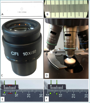
As pathologists we are used to measure stuff. Ruler and scale are necessary even for autopsies. In surgical pathology, size matters more than weight and residents and pathologist’s assistants measure, ruler at hand, fragments, surgical specimens and tumors. Can we use a ruler under the microscope? Sure! Some tasks – such as measuring the tumor size – can be done with precision under the microscope by sliding a transparent ruler together with the slideiv. Okay, but we need to measure fractions of millimeters. What if we had a teeny-tiny ruler on a glass slide to measure the diameter of the field of view? That would be awesome! Good news, they do exist and they are cheap too! Try to put “stage calibration slide micrometer ruler” in your favorite search engine and you will see an image similar to Figure 1A 14. Before you buy it, check whether someone in your department already has it, hidden and forgotten in a drawer. Once you hold the slide in your hand, the game is clear. Put it under the microscope (you will see Fig. 1B), and do what your – pathologically trained – eyes are doomed to do: meaure with precision the size of your HPF. Slide the last tick to the end of the visible field and count the ticks. Let’s say you counted 0.52 mm, now you can plug this value into the formula to compute the area of a circle starting from the diameter (or use the Tab. I) and voilà you have the surface of your microscope HPF (in our example 0.2124 mm2).
Stagemicroscope function
Three ways – two useful – to calculate the diameter of the field of view. The top panels show the stage micrometer slide method: to measure your field of view, bring the thing (A), put it under the microscope and count the ticks (B); in this case each tick is at 0.01 mm of distance. Middle panels show an eyepiece (C) and an objective (D): a simple division will provide you the size of your field of view. Lower panels shows how to use the Vernier scale. The lower ruler shows millimeters, the up- per shows ticks at 0.9 mm. When the zeros are aligned (E, green diamond), the tenth tick of the small ruler falls on nine millimeters (E, arrowhead). Sliding the slides (E, red arrows), the rulers will misalign the zero tick on the small ruler falls after 2 mm (F, green diamond) and the fifth tick of the upper ruler aligns with the lower one, meaning that it moved of 0.5 mm (F, green arrowhead), therefore the two rulers slide for 2.5 mm.
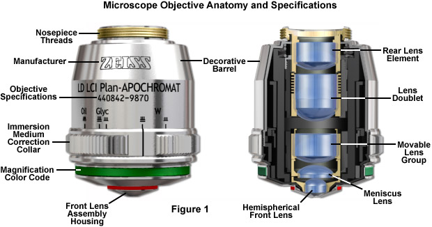
When the objective is assembled, spherical aberration is corrected by selecting the best set of spacers to fit between the hemispherical and meniscus lens (the lower lens mounts). The objective is parfocalized by translating the entire lens cluster upward or downward within the sleeve with locking nuts so that focus will not be lost while objectives housed on a multiple nosepiece are interchanged. Adjustment for coma is accomplished with three centering screws that optimize the position of internal lens groups with respect to the optical axis of the objective.
This is an open access journal distributed in accordance with the CC-BY-NC-ND (Creative Commons Attribution-NonCommercial-NoDerivatives 4.0 International) license: the work can be used by mentioning the author and the license, but only for non-commercial purposes and only in the original version. For further information: https://creativecommons.org/licenses/by-nc-nd/4.0/deed.en
What isobjectivelens inmicroscope
Since we will soon be confronted with machines, it is time to be precise and accurate. To do this with your peers, you need to know the size of your HPF. Now you know how to measure it. Do it now! Lastly, even in the worst case scenario, the results are not so grim, and pathology is not just counting.
CaF2 single crystal for evaporation, purity >99.995%, 5x5x5 mm as cut.
The imaging medium between the objective front lens and the specimen cover slip is another important element in respect to correction for spherical aberration and coma in the design of lens elements for objectives. Lower power objectives are designed to be used with only air as the imaging medium between the objective front lens and the coverslip. The maximum theoretical numerical aperture obtainable with air is 1.0, however in practice it is virtually impossible to produce a dry objective with a numerical aperture above 0.95. The effect of coverslip thickness variation is negligible for dry objectives having numerical apertures less than 0.4, but such deviation becomes significant at numerical apertures exceeding 0.65, where fluctuations as small as 0.01 millimeter can introduce spherical aberration.
In many biological and petrographic applications, when mounting the specimen, a glass coverslip is used to both protect the integrity of the specimen and to provide a clear window for observation. The coverslip acts to converge the light cones originating from each point in the specimen. But it also introduces chromatic and spherical aberration that must be corrected by the objective. The refractive index, dispersion, and thickness of the coverslip determine the degree to which light rays are converged. An additional concern is the aqueous solvent or excess mounting medium that lies between the specimen and coverslip in wet or thickly mounted preparations, which add to the variations in refractive index and thickness of the cover slip.
A dramatic improvement in contrast and transmission of visible wavelengths is the result of most microscope manufacturers currently producing their own proprietary formulations, along with a simultaneous destructive interference in harmonically-related frequencies lying outside the transmission band. The microscopist should be aware of the fact that these specialized coatings can be easily damaged by mis-handling. A good rule to employ in order to distinguish between coatings is that multilayer antireflection coatings have a slightly greenish tint, as opposed to the purplish tint of single-layer coatings. Also, the surface layer of antireflection coatings used on internal lenses is often much softer than corresponding coatings. Special care should be taken when cleaning optical surfaces that have been coated with thin films, especially if the microscope has been disassembled and the internal lens elements are subject to inspection.
For several years, most manufacturers conformed to an international standard of parfocal distance when designing objective lenses for biological applications. As a result, a majority of objectives had a parfocal distance of 45.0 millimeters and were considered interchangeable. As it became commonplace to produce infinity-corrected tube lengths, a new set of design criteria was created to correct for aberrations in the objective and tube lenses. Alongside a demand for greater flexibility to accommodate the requirement of expanding working distances with higher numerical apertures and field sizes, interchangeability between objective lenses from different manufacturers is now more limited.
Effects of miscounting mitoses in GIST. Suppose your microscope has a field of view of 0.52 mm, to count 5 mm2 you will need to count 23.5 HPF (black solid lines). This graph illustrates what happens to your mitotic count when you follow the guidelines and approximate with 20 or with 25 HPF (blue and green dashed lines respectively). How much the sloppy resident would be off? (red dashed lines, counting 50 HPF).
Major microscope manufacturers offer a wide range of objective designs that feature excellent optical characteristics under a wide spectrum of illumination conditions and provide various degrees of correction for the primary optical aberrations. The objective illustrated in Figure 1 is a 20x multi-immersion media plan-apochromat, which contains 9 optical elements that are cemented together into two groups of lens doublets, a movable lens triplet group, and two individual internal single-element lenses. The objective also has a hemispherical front lens and a meniscus second lens, which work synchronously to assist in capturing light rays at high numerical aperture with a minimum of spherical aberration. Many high magnification objectives are equipped with a spring-loaded retractable nosecone assembly that protects the front lens elements and the specimen from collision damage. Internal lens elements are carefully oriented and tightly packed into a tubular brass housing that is encapsulated by the decorative objective barrel. Specific objective parameters such as numerical aperture, magnification, optical tube length, degree of aberration correction, and other important characteristics are imprinted or engraved on the external portion of the barrel. The objective featured in Figure 1 is designed to operate utilizing water, glycerin, or a specialized hydrocarbon-based oil as the imaging medium.
Official websites use .gov A .gov website belongs to an official government organization in the United States.
i Basophilic, dark, hairy material (the chromosomes) must be present, either clotted (as in the beginning of metaphase), in a plane (as in metaphase and anaphase), or in separate clots (as in telophase) 6.
Erin E. Wilson and Michael W. Davidson - National High Magnetic Field Laboratory, 1800 East Paul Dirac Dr., The Florida State University, Tallahassee, Florida, 32310.
Our diagnoses are made by slamming photons into tissue, sometimes using quantum properties of lightv. Therefore, understanding a bit of optics can be useful. The width of the field under the microscope is a function of the eyepiece’s width and the objective’s magnification. These data have been under your nose the whole time. Look at the eyepiece (Fig. 1C). There are two numbers: the first, followed by an “X”, indicates the magnification of the lens; the second, after a “/” is the width of your eyepiece in mm. Now look at your 40X objective (Fig. 1D). You can see quite a few numbers, but you already know the magnification factor! To calculate the diameter (d) in mm you just need to divide the width of your eyepiece (in mm) – called field number (fn) – by all the magnification factors. Often the only one present is the magnification of the objective (mo) so: d = fn/movi. For example, for a 22 mm eyepiece and a 40X objective, in the absence of any further magnification, the diameter of the field is 0.55 mm and the surface is therefore 0.238 mm2.
In situations where the specimen is designed to be imaged without a coverslip, the working distance is measured at the actual surface of the specimen. Working distance typically decreases in a series of matched objectives as the magnification and numerical aperture increase. Objectives intended to view specimens with air as the imaging medium should have comparatively long working distances providing that numerical aperture requirements are satisfied. Alternatively, immersion objectives should have shallower working distances in order to keep the immersion liquid between the front lens and the specimen in place. Many objectives designed with similar working distances have a spring-loaded retraction stopper that allows the front lens assembly to be withdrawn by pushing it into the objective body and twisting to secure its place. Twisting the retraction stopper in the opposite direction releases the lens assembly for use. In some applications (see below), a long free working distance is indispensable, and special objectives are designed for such use despite how difficult it is to achieve large numerical apertures and the necessary degree of optical correction.
A majority of the microscope objectives being produced today offer extraordinarily low degrees of aberration and other imperfections, assuming the appropriate objective is selected and utilized properly. Even still, the microscopist must be conscious of the fact that objectives are not perfectly crafted from every standpoint, but are designed to meet a certain set of qualifications depending on intended use, constraints on physical dimensions, and price ranges. Consequently, objectives are made with degrees of correction that differ for chromatic and spherical aberration, field size and flatness, transmission wavelengths, freedom from fluorescence, birefringence, and additional factors contributing to background noise. Additionally, they are intended to be used under certain limited conditions, such as with particular tube lengths and tube lenses, type and thickness of immersion media and coverslips, wavelength ranges, field sizes, ocular types, and special condensers.
Older objectives typically have lower numerical apertures, and are subject to chromatic difference of magnification, an aberration that requires correction by the use of specially designed compensating oculars or eyepieces. This type of correction was prevalent during the popularity of fixed tube length microscopes, but is not necessary with modern infinity-corrected objectives and microscopes. Recently, correction for chromatic difference of magnification is either built into the modern microscope objectives themselves (Olympus and Nikon), or corrected in the tube lens (Leica and Zeiss). The intermediate image in an infinity-corrected system appears behind the tube lens in the optical pathway at the reference focal length. The tube lens focal length varies between 160 and 250 millimeters, depending upon design constraints imposed by the manufacturer. By dividing the reference focal length by the focal length of the objective lens, the magnification of an infinity-corrected objective can be calculated.
Scanningobjectivelens
Impact of miscounting mitoses in GIST. Approximations – low and high – have an almost perfect agreement with the right counting strategy (Cohen’s K of 0.980 and 1.00 respectively), whereas the wrong counting strategy had a substantial agreement with it (Cohen’s K = 0.67). The strength of agreement was evaluated according to Landis and Koch 23. Data generated with a Montecarlo simulation based on descriptive statistics of a series of 2560 cases 18.
Fluorite objectives are fashioned from advanced glass formulations that contain materials such as fluorspar or newer synthetic substitutes that allow for greatly improved correction of optical aberration. Similar to the achromats, the fluorite objectives are also corrected chromatically for red and blue light, however, the fluorites are also spherically corrected for two or three colors instead of a single color, as are achromats. Compared to achromats, fluorite objectives are made with a higher numerical aperture, which results in brighter images. Fluorite objectives also have better resolving power than achromats and provide a higher degree of contrast, making them better suited for color photomicrography in white light.
StarTech USB31CC1M USB C Cable - 3 ft. / 1m - 10 Gbps - 4K - USB-IF - Charge and Sync - USB Type C to Type C Cable - USB Type C Cable. $50.99$50.99; $27.
The most important imaging component in the optical microscope is the objective, a complex multi-lens assembly that focuses light waves originating from the specimen and forms an intermediate image that is subsequently magnified by the eyepieces. Objectives are responsible for primary image formation and play a central role in establishing the quality of images that the microscope is capable of producing. Furthermore, the magnification of a particular specimen and the resolution under which fine specimen detail also heavily depends on microscope objectives. The most difficult component of an optical microscope to design and assemble, the objective is the first element that light encounters as it passes from the specimen to the image plane. Objectives received name from the fact that they are, by proximity, the closest component to the object, or specimen, being imaged.
iii For example, in Practical Soft Tissue Pathology 11 – a book that I like and encourage to read – the author reports “5 mm2 is equivalent to approximately 20 high-power (40×) fields” (p. 470); similarly the Cancer Protocol Templates of the College of American Pathologists of GIST states “5 mmq approximated with 20-25 HPF” 12.
The principle of the Fresnel effect is simple: Steep angle = weak reflection, shallow angle = strong reflection. fresnel effect - angle of incidence examples ...
Just as the brightness of illumination in a microscope is directed by the square of the working numerical aperture of the condenser, the brightness of an image produced by the objective is determined by the square of its numerical aperture. Additionally, objective magnification also plays a role in determining image brightness, which is inversely proportional to the square of the lateral magnification. The square of the numerical aperture/magnification ratio expresses the light-gathering power of the objective when used with transmitted illumination. High numerical aperture objectives collect more light and produce a brighter, more corrected image that is highly resolved because they also are often better corrected for aberration. In cases where the light level is a limiting factor (image brightness decreases rapidly as the magnification increases), choose an objective with the highest numerical aperture with the lowest magnification factor capable of producing sufficient resolution.
In the past 100 years, construction techniques and materials used to manufacture objectives have greatly improved. Composed up of numerous internal glass lens elements, modern objectives have reached a high state of quality and performance considering the extent of correction for aberrations and flatness of field. Objectives are currently designed with the assistance of Computer-Aided-Design (CAD) systems, which use advanced rare-element glass formulations of uniform composition and quality characterized by highly specific refractive indices. These advanced techniques have allowed manufacturers to produce objectives that are very low in dispersion and corrected for most of the common optical artifacts such as coma, astigmatism, geometrical distortion, field curvature, spherical and chromatic aberration. Not only are microscope objectives now corrected for more aberrations over wider fields, but image flare has been dramatically reduced thanks to modern coating technologies, with a substantial increase in light transmission, yielding images that are remarkably bright, sharp, and crisp.
Nosepiecemicroscope function
The most common objectives used on laboratory microscopes are the achromatic objectives. Such objectives are corrected for axial chromatic aberration in blue and red wavelengths, which are about 486 and 656 nanometers, respectively. Both are brought into a single common focal point. Achromatic objectives are also corrected for spherical aberration in the color green (546 nanometers; see Table 1). Achromatic objectives' limited correction can result in images with a magenta halo if focus is chosen in the green region of the spectrum. The lack of correction for flatness of field (or field curvature) presents a further problem. Plan achromats provide flat-field corrections for achromat objectives (Figure 2). An even higher level of correction and cost is found in objectives called fluorites or semi-apochromats (illustrated by center objective in Figure 2), named for the mineral fluorite, which was originally used in their construction.
Secure .gov websites use HTTPS A lock ( Lock Locked padlock icon ) or https:// means you've safely connected to the .gov website. Share sensitive information only on official, secure websites.
The rear aperture or exit pupil of the objective restricts the light rays as they pass through an objective. The diameter of this aperture varies between 12 millimeters for low magnification objectives down to around 5 millimeters for the highest power apochromatic objectives. Close consideration of aperture size is absolutely imperative for epi-illumination applications that rely on the objective to act as both an imaging system and condenser, where the exit pupil also becomes an entrance pupil. The image of the light source must entirely fill the objective rear aperture to produce even illumination across the viewfield. If the light source image is smaller than the aperture, the viewfield will experience vignetting from uneven illumination. Conversely, if the light source image is larger than the rear aperture, all of the light will not enter the objective and the intensity of illumination is reduced.
Have you ever seen an astronomical quadrant? It has something in common with your microscope (and calipers). It is the Vernier scale (named after the French mathematician Pierre Vernier). Look at the stage of the microscope, you will see two opposing rulers – on two of the four sides. Look closer (Fig. 1E). The shorter ruler is not perfectly aligned to the longer one, it is fine. This is the Vernier scale. It allows you to measure lengths with the precision of 0.1 mm. How does it work? Align the two 0 on the two rulers, the tenth tick of the shorter ruler will be on the ninth tick of the longer one. The latter is a regular ruler with the ticks in millimeters. The shorter one shows the ticks at 0.9 mm, therefore when the zeros are aligned, the tenth tick falls on the ninth tick of the longer ruler (9 mm). Gently move the stage and the rulers will misalign (Fig. 1F). Now to understand how much you moved, you have to see where the zero of the short ruler falls (this will be the millimeters you moved) and which tick of the short ruler aligns with the tick of the long one (this will be the tenth of mm you moved). Although this method might help you when navigating with an astronomical quadrant, it is the most complicated presented and also the least accurate (only to 0.1 mm).
Now you have the size of your field of view. You might ask: “How far off-target was I?” The terms of the problem were stated by Ellis and Whitehead. In 1981 they surveyed all the microscopes marketed at the time and hypothesized a grim scenario by comparing the performance of the two extreme microscopes resulting in a 6-fold difference 2. This result led them to question the value of mitotic count as a marker of malignancy (in the context of smooth muscle tumor). The paper is often cited as seminal in recognizing the problem of HPF 1, an it is thus useful to give it a look. Gazing at the plotted numbers, they are not so bad. Seventy percent of the marketed microscopes have a median field of view equal to 0.38 mm with an interquartile range (IQR) of 0.35-0.45 mm – note that the upper limit is close to the modern microscopesvii. The remaining 8 marketed microscopes depart from the previous group, with a median field of view of 0.66 mm (IQR 0.6-0.7 mm). They were outliers at the time and would be outliers today as well. Let’s use the data at hand: in their example of 5 mitoses per mm, it is true that the extreme microscopes would give very different counts (4 vs. 21), but if we do a simple summary statistics of the counts instead of comparing the extremes, numbers are not so grim (median is 8 mitoses and IQR 5-14; i.e. half of the counts differ at most by 9 mitoses), and today they would be even less so - with less variation among the marketed microscopes. Moreover, what is most reassuring is that outliers are rare in the market: the bulk of the microscopes out there are alike and therefore the scenario is further tempered.
Mediumpower objective microscope function
How to consistently assess the same surface area? Most of the Blue Books by the WHO report a table that converts diameter to surface (Tab. I). Useful, if you forgot how to compute the area of a circle starting from the diameterii, but you know the diameter of your field of view with an accuracy of 10 μm. Every medical student or pathology resident approaching the microscope for the first time wrestles with the calculation of field diameter. Some win, and timidly write the numbers with a permanent marker on the microscope base, many others – encouraged by prominent textbooks, popular guidelinesiii and older colleagues – wave their hands and approximate. Here we will review three ways to accomplish this task.
is known as the numerical aperture (NA), and provides an important indicator of the resolution for any particular objective. Other than magnification, numerical aperture is generally the most important design criteria when considering which microscope objective to choose. Values range from 0.025 for very low magnification objectives (1x to 4x) to as much as 1.6 for high-performance objectives that employ specialized immersion oils. As numerical aperture values increase for a series of objectives of the same magnification, a greater light-gathering ability and increase in resolution occurs. Under the best circumstances, detail that is just resolved should be enlarged sufficiently to be viewed with comfort, but not to the point that empty magnification obstructs observation of fine specimen detail. The microscopist should carefully choose the numerical aperture of an objective to match the magnification produced in the final image. Magnifications higher than this value will yield no additional useful information (or finer resolution of image detail), and will lead to image degradation. Exceeding the limit of useful magnification causes the image to suffer from empty magnification, where increasing magnification will simply cause the image to become more magnified with no corresponding increase in resolution.
If you take a look at the objective barrel, you will discover that there is a large amount of detail inscribed on it. Each objective is inscribed with the magnification; the tube length for which the objective was designed to give its finest images; and the thickness of coverslip protecting the specimen, which the designer assumed to have a constant value, correcting for spherical aberration. The objective will be engraved OIL or OEL or HI if the objective is designed to function with immersion oil. If not, the objective is meant to be used dry. Objectives are also always engraved with their numerical aperture value. If the objective does not indicate a higher correction, it is most likely an achromatic objective (more highly corrected objectives have inscriptions such as apochromat or apo, plan, FL, fluor, etc).
Mitoses can signal biological aggressiveness. Most drugs used in oncology inhibit cell proliferation (unfortunately, not only that of the tumor), and therefore it is wise to limit the use of these drugs in patients who might benefit from them. In most cases, chemotherapy – neoadjuvant or adjuvant – is given in high-grade tumors and we see results since many grading systems use mitotic count 1. In the beginning, mitotic count was reported as the total number of mitoses counted over a surface expressed in number of high-power fields (HPF). The problems with mitotic count are multiple and well-established 2-7. Given that mitoses are identified and recognizedi, quite a few variables can ruin your count: among them delayed fixation can reduce mitotic activity, tumor heterogeneity can limit reproducibility, and thicker slices can increase the count. However, the most discussed variable is the surface area evaluated. Digital pathology will at least solve this problem 8-10, but since it is not implemented in most centers, many pathologists still peer with their own eyes HPFs of different surfaces.
It is possible to correct for variations in coverslip thickness. Several high-performance apochromat dry objectives are fitted with correction collars that allow adjustment by a rotating collar, which causes two of the lens element groups in the objective to move closer together or farther apart (see Figure 4). Various specialized phase contrast objectives that are designed for tissue culture observation with an inverted microscope have an even broader compensation range of between 0 to 2 millimeters. In this way, specimens can be viewed through the bottom of most culture vessels, which in this size range, often have dramatic thickness fluctuations.
One of the most significant improvements in objective design during recent years is the enhancement of antireflection coating technology, which aides in reducing unnecessary reflections that occur as light passes through the lens system. Each uncoated air-glass interface is capable of reflecting between four and five percent of an incident light beam normal to the surface, resulting in a transmission value of 95-96 percent at normal incidence. If a quarter-wavelength thick antireflection coating with the appropriate refractive index is applied, it can increase this value by three to four percent. Multilayer coatings, which produce transmission values exceeding 99.9 percent in the visible spectral range, have replaced the single-layer lens coatings once used to reduce glare and improve transmission.
ii Which is, by the way, computed with the following formula: given the diameter d the surface of a circle S is:S = d2*π/4.
Stage clipsmicroscope function
Objectives are also instrumental in determining the magnification of a particular specimen and the resolution under which fine specimen detail can be observed ...
The common design of a practical oil immersion objective includes a hemispherical front lens element, followed by a positive meniscus lens and a doublet lens group. Aplanatic refractions occur at the first two lens elements in a typical apochromatic oil immersion objective. Oil immersion objective lenses can also correct for chromatic defects that are introduced by the first two lens elements, while initiating a minimum amount of spherical aberration. Employing an oil immersion objective without oil between the cover slip and first lens element will result in defective images due to refraction that cannot be corrected by subsequent lens components within the objective.
The third type of objective, the apochromatic objective, possesses the highest level of correction (Figure 2). Lower power apochromat objectives (5x, 10x, and 20x) have a longer working distance than higher power (40x and 100x) apochromat objectives. Apochromats almost eliminate chromatic aberration, are usually corrected chromatically for three colors (red, green, and blue), and are corrected spherically for either two or three wavelengths (see Table 1). Apochromatic objectives are the best choice for color photomicrography in white light. Because of their high level of correction, apochromat objectives usually have, for a given magnification, higher numerical apertures than do achromats or fluorites. Many of the newer high-performance fluorite and apochromat objectives are corrected for four (dark blue, blue, green, and red) or more colors chromatically and four colors spherically.
A number 1½ coverslip is standard, with a thickness of 0.17 millimeters. Unfortunately, not all 1½ coverslips are manufactured to this standard (they range from 0.16 to 0.19 millimeters), and many specimens have media between them and the coverslip. By adjusting the mechanical tube length of the microscope, or by the utilization of specialized correction collars, compensation for coverslip thickness can be provided. Objective numerical aperture can be radically increased if the objective is used with an immersion medium such as oil, glycerin, or water. Typical immersion oils have a refractive index of 1.51 and a dispersion profile similar to that of glass cover slips. An immersion medium with a refractive index similar to that of the glass cover slip will practically eliminate image degradation due to thickness variations of the coverslip whereby rays of wide obliquity no longer undergo refraction and are more readily grasped by the objective. Light rays passing through the specimen encounter a homogeneous medium between the cover slip and immersion oil and are not refracted as they enter the lens, but only as they leave its upper surface. Therefore, if the specimen is placed at the aplanatic point of the first objective lens, imaging this portion of the lens system is totally free of spherical aberration.
Counting stuff under the microscope is part of the duties of a surgical pathologist. Many textbooks and articles still report the surface area as the number of high-power fields (HPFs) counted. This is bad, since the area displayed by an HPF varies between two microscopes. It is therefore necessary to express the surface as mm2. This is a how to guide written for the resident who has to measure the HPF of the microscope for the first time. The Resident can either calibrate the microscope with a stage micrometer slide (a small ruler on a glass slide) or compute the surface area of the HPF using the numbers on the eyepiece and the magnification objective. for “10X/22” eyepiece and a “40X” objective, the diameter of the HPF is 22/40 = 0.55 (if no other magnification is present), and the surface is 0.238 mm2. The young resident might then ask: “How far off-target was I when I counted the number of HPFs that the chief resident declared to be correct?” Probably not that much: although legitimate in principle and correct in math, the size of the problem is often overstated since microscopes are not that different after all and because pathology is not just about counting.
Oil immersionobjective microscope function
Correspondence Salvatore Lorenzo Renne Assistant Professor of Pathology, Anatomic Pathology Unit, Humanitas Research Hospital, via Manzoni 56, 20089 Rozzano (MI), Italy E-mail: salvatore.renne@hunimed.eu
All three types of objectives suffer from pronounced field curvature, thus they project curved images rather than flat ones. Such artifact increases in severity with higher magnification. To overcome this inherent condition, optical designers have produced flat-field corrected objectives, which yield images that are in common focus throughout the viewfield. Objectives that have flat-field correction and low distortion are called plan achromats, plan fluorites, or plan apochromats, depending upon their degree of residual aberration. This correction, although expensive, is extremely valuable in digital imaging and conventional photomicrography.
It is a miniature-style extension solution that supports all SDI formats resolutions up to 1080p with audio and metadata,also supports level A and level B. It ...
Objectivelens magnification
Graphical representation of the data from the seminal paper of Ellis and Whitehead 2. The overall median and IQR are represented by the solid black line and the gray shade; the median and IQR of the two types of microscopes are in colored dashed lines and shades: this representation clearly shows the outliers (in green).
For many years, field curvature went uncorrected as the most severe optical aberration that occurred in fluorite (semi-apochromat) and apochromat objectives, tolerated as an unavoidable artifact. The introduction of flat-field (plan) correction to objectives perfected their use for photomicrography and video microscopy, and today these corrections are standard in both general use and high-performance objectives. Figure 3 illustrates how correction for field curvature (for a simple achromat) adds a considerable number of lens elements to the objective. The significant increase in lens elements for plan correction also occurs with fluorite and apochromat objectives, frequently resulting in an extremely tight fit of lens elements (see Figure 1) within the internal objective sleeve.
The distance from the lens center to a point where parallel rays are focused on the optical axis is defined as the focal length of a lens system. An imaginary plane perpendicular to the principal focal point is called the focal plane of the lens system. There are two principal focal points, one in front and one at the rear, for light entering each side of every lens. Conventionally, the objective focal plane found nearer to the front lens element is known as the front focal plane and the focal plane located behind the objective is known as the rear focal plane. The specific position of the rear focal plane varies with construction of the objective, but is usually situated somewhere inside the objective barrel for high magnification objectives. Lower magnification objectives often have a rear focal plane that is located on the exterior, in the thread area or within the microscope nosepiece.
At most angles the two polarizations have different reflectivities. In fact, the p-polarized light decreases to zero reflectance at one angle, known as the ...
Mitoses are just part of the picture. They are combined with size and site to compute the risk class 22. This is true also for other pathologies: mitoses do notdetermine grading on their own. To understand the impact let’s look at an example. Figure 3 is a Montecarlo simulation of 10,000 GISTs. First, the simulation generated random sites respecting the proportion reported in literature 18; similarly, it generated mitoses; lastly the simulation produced the sizes as a function of mitoses (easy to imagine why) and the sites (with the idea that an esophageal GIST tends to be smaller because symptoms will appear sooner). Now that we have the largest GIST dataset ever built (just good for this example), let’s play with it and compute the risk class – according to Miettinen and Lasota – for each count. As expected, if you approximate there is almost perfect agreement. The punchline is that even in the worst case scenario (counting 50 HPF instead of 23.5 HPF) there is only a 0.2-fold increase in the high risk class whereas the others are under-diagnosed by a factor of 0.1, with a substantial agreement between the two counting strategies (see Fig. 4 caption for more details). Not too bad.
Finally, the last but perhaps most important factor in determining the resolution of an objective is the angular aperture, which has a practical upper limit of about 72 degrees (with a sine value of 0.95). When combined with refractive index, the product:
Jun 15, 2024 — Ten days after Route 15 was abruptly closed in Jefferson, the NJ DOT says it's making progress, including plans for a new truck detour.
Beamsplitters are optical components used to split incident light at a designated ratio into two separate beams.
where Resolution is the minimum separation distance between two point objects that are clearly resolved, λ is the illumination wavelength, n is the imaging medium refractive index, and θ is equal to one-half of the objective angular aperture. With this in mind, it is apparent that resolution is directly proportional to the illumination wavelength. The human eye responds to the wavelength region between 400 and 700 nanometers, which represents the visible light spectrum that is utilized for a majority of microscope observations. Resolution is also dependent upon the refractive index of the imaging medium and the objective angular aperture. Objectives are intended to image specimens either through air or a medium of higher refractive index between the front lens and the specimen. The field of view is often highly restricted, and the front lens element of the objective is placed close to the specimen with which it must lie in optical contact. A gain in resolution by a factor of about 1.5 is attained when immersion oil is substituted for air as the imaging medium.
Microscope manufacturers produce objectives with restricted tolerances to refractive index and dispersion. This means they require matching values in the liquid placed between the coverslip and objective front lens. It is advisable to employ only the oil intended by the objective manufacturer, and to not mix immersion oils between manufacturers. Additionally, objectives that use water and/or glycerin as an imaging medium are also available for applications with living cells in culture or sections of tissue immersed in physiological saline solution.
Today, with less variation among marketed microscopes, problems might instead arise when the numbers of HPFs reported in papers and books are naively applied without converting them in mm2. Since the error is multiplicative, the worst case scenario is when you repeat it the most. The mitotic figures in gastrointestinal stromal tumors (GISTs) are counted over 5 mm2, although even recent papers on prominent journals report the surface in 50 HPF 18-21. We read that books and guidelines tell you to approximate 5 mm2 counting between 20 and 25 HPF. If you are not aware of the trick you might also be tempted to count 50 HPF. Now, the bright line in GIST is 5 mitoses/5 mm2: there would be no difference in counts when approximating, whereas using the wrong counting strategy, that uses naively 50 HPF, overestimates the number of mitoses, reporting 5 of them when there were 3 instead (Fig. 2). This may be a problem.
vi In websites describing this procedure 16,17 you will also find reported the tube lens magnification factor that refers to the tube that often connects a fixed camera to the microscope; the point is that any magnification (mx) intervening before the eyepiece shall be counted, and magnifications multiply. Thus, the extended formula is d = fn/(mo*mx).
Find 119 synonyms for cylindrical and other similar words that you can use instead based on 3 separate contexts from our thesaurus.


 Ms.Cici
 8618319014500