
Olympus SZ-ST Stereo/Dissecting Microscope - olympus dissecting microscope
Trench banding, where the band bar is elevated above the bottom of the bearing bars, is appropriate for drainage applications. The elevated band bar allows for efficient drainage and will not trap liquids between the band bar and the grating support.
– Grating in which the bearing bars and cross bars are joined at their intersections by either electro-forging or conventional hand welding.
Products will display discoloration from welding, cutting and grinding. Satisfactory for industrial or process applications where appearance is not a consideration.
LIDT in energy density vs. pulse length and spot size. For short pulses, energy density becomes a constant with spot size. This graph was obtained from [1].
Figure 12 plots the trace from Figure 11, as well as traces measured for the other three retroreflectors, on the same scale but vertically shifted as a visual aid. These results indicate that an antireflective-coated front face suppresses power oscillations in beams output by solid prism retroreflectors. The power output by hollow retroreflectors does not oscillate, since there is no material boundary at the front face.
– An area of grating removed to clear an obstruction or to permit pipes, ducts, columns, etc. to pass through the grating.
Conditions for InterferenceSince the output of solid prism retroreflectors consists of beams that have travelled different optical path lengths, they will interfere if:
Reflections from the Front FaceAs illustrated in Figure 10, light can make multiple passes through a solid prism retroreflector, depending on whether the light reflects from or is transmitted through interfaces between the front face and the surrounding medium.
Thorlabs' Hollow Retroreflector Mirrors use three orthogonal surfaces to reflect light back to the source at the same angle as the incident beam, regardless of changes in position or alignment, creating an inverted image. This insensitivity to mirror alignment and lack of refraction through glass make these hollow retroreflectors ideal for applications where dispersion, chromatic aberrations, material absorption, or front surface reflections from glass prisms are undesirable. Examples of such applications include interferometry and optical delay lines.
– Grating composed of straight bearing bars and bent connecting bars, which are joined at their contact points, by riveting.
Aluminum Bar Grating is lightweight, corrosion resistant, non-sparking and has an unmatched strength-to-weight ratio. Manufactured from ASTM B221, 6063 or 6061 alloy, aluminum grating is available in four distinct products, type “ADT” Dovetail Pressure Locked , type “SG” Swaged Rectangular Bar, type “SGI” Swaged “I” Bar, and type “SGF” Swaged Flush-Top and. All four products are available with bearing bar spacing ranging from 19/16″ (1-3/16″) to 7/16″ on center and with cross bars at either 4″ or 2″ on center. Rectangular bar products are manufactured with standard plain or optional serrated walking surfaces and “I” bar products are manufactured with a standard skid-resistant striated walking surface. Aluminum products are typically shipped “mill finish” with no additional treatment. For architectural applications or highly corrosive environments, supplemental anodizing, chemical cleaning or powder coat finishes are available.
As produced, stainless steel products typically display discoloration caused by the introduction of heat during welding, cutting or grinding processes. If appearance is important to your application, consideration should be given to secondary cleaning or electro-polishing.
What isgratingin physics
Figure 11 plots the normalized measurements made for the TIR solid prism retroreflector. As the AOI increased, the centers of the first- and third-pass beams shifted away from one another. At AOIs greater than around ±1°, the beams' 1/e2 diameters no longer overlapped. This resulted in the oscillation amplitude decreasing with AOI. The range of AOIs over which oscillations were significant would increase if the detector were located closer to the front face.
Output Polarization StateTwo sets of six measurements were made for both a PS975M TIR solid prism retroreflector and a PS975M-M01B backside-gold-coated solid prism retroreflector. Input light was linearly polarized, vertically for one set of measurements and horizontally for the other. In a set, each measurement was taken with the beam aligned to a different zone. At all three reflections, the beam was confined within a single zone.
– A panel of grating having carriers and a nosing attached by welding, and designed specifically to serve as a stair tread.
Diffractiongratingformula
Manufactured with highly efficient “I” shaped extruded bearing bars, type “SGI” aluminum grating carries the same load as 3/16” thick rectangular bar type “SG” aluminum grating, but weighs slightly less per square foot. Additionally, the striated top and bottom flanges of the “I” bar provide enhanced skid resistance without the cost of serration.
Manufactured with a unique, extruded cross bar that is flush with the top surface of the bearing bars after swaging, type “SGF” aluminum grating provides an enhanced walking surface for areas subject to continuous pedestrian traffic. Available in rectangular bar with plain or serrated surfaces, type “SGF” aluminum grating is also available in ADA conforming spacings for applications located in the public way.
In order to illustrate the process of determining whether a given laser system will damage an optic, a number of example calculations of laser induced damage threshold are given below. For assistance with performing similar calculations, we provide a spreadsheet calculator that can be downloaded by clicking the button to the right. To use the calculator, enter the specified LIDT value of the optic under consideration and the relevant parameters of your laser system in the green boxes. The spreadsheet will then calculate a linear power density for CW and pulsed systems, as well as an energy density value for pulsed systems. These values are used to calculate adjusted, scaled LIDT values for the optics based on accepted scaling laws. This calculator assumes a Gaussian beam profile, so a correction factor must be introduced for other beam shapes (uniform, etc.). The LIDT scaling laws are determined from empirical relationships; their accuracy is not guaranteed. Remember that absorption by optics or coatings can significantly reduce LIDT in some spectral regions. These LIDT values are not valid for ultrashort pulses less than one nanosecond in duration.
According to the test, the damage threshold of the mirror was 2.00 J/cm2 (532 nm, 10 ns pulse, 10 Hz, Ø0.803 mm). Please keep in mind that these tests are performed on clean optics, as dirt and contamination can significantly lower the damage threshold of a component. While the test results are only representative of one coating run, Thorlabs specifies damage threshold values that account for coating variances.
This adjustment factor results in LIDT values of 0.45 J/cm2 for the BB1-E01 broadband mirror and 1.6 J/cm2 for the Nd:YAG laser line mirror, which are to be compared with the 0.7 J/cm2 maximum energy density of the beam. While the broadband mirror would likely be damaged by the laser, the more specialized laser line mirror is appropriate for use with this system.
When pulse lengths are between 1 ns and 1 µs, laser-induced damage can occur either because of absorption or a dielectric breakdown (therefore, a user must check both CW and pulsed LIDT). Absorption is either due to an intrinsic property of the optic or due to surface irregularities; thus LIDT values are only valid for optics meeting or exceeding the surface quality specifications given by a manufacturer. While many optics can handle high power CW lasers, cemented (e.g., achromatic doublets) or highly absorptive (e.g., ND filters) optics tend to have lower CW damage thresholds. These lower thresholds are due to absorption or scattering in the cement or metal coating.
– A flat bar welded to the end of a grating panel, or along the side of a cutout, and extending neither above nor below the bearing bars.
Beam diameter is also important to know when comparing damage thresholds. While the LIDT, when expressed in units of J/cm², scales independently of spot size; large beam sizes are more likely to illuminate a larger number of defects which can lead to greater variances in the LIDT [4]. For data presented here, a <1 mm beam size was used to measure the LIDT. For beams sizes greater than 5 mm, the LIDT (J/cm2) will not scale independently of beam diameter due to the larger size beam exposing more defects.
When an optic is damaged by a continuous wave (CW) laser, it is usually due to the melting of the surface as a result of absorbing the laser's energy or damage to the optical coating (antireflection) [1]. Pulsed lasers with pulse lengths longer than 1 µs can be treated as CW lasers for LIDT discussions.
Reflectiongrating
The load tables on the pages within this website provide load/deflection criteria for most common applications. These tables provide a concise reference allowing the specifying authority to select the appropriate bearing bar size and spacing for the intended application. Pedestrian loads are commonly analyzed with uniform and concentrated loads. For pedestrian comfort, deflection is typically limited to 1/4″. Heavy duty and vehicular load tables are presented for specific load conditions. Heavy duty load tables are presented with deflection limited to the lesser of 1/8″ or L/400. If your application is not addressed by the load tables found in this website, please contact Interstate Gratings. We will gladly discuss the merits of our diverse products and assist in selecting the product most appropriate for your application.
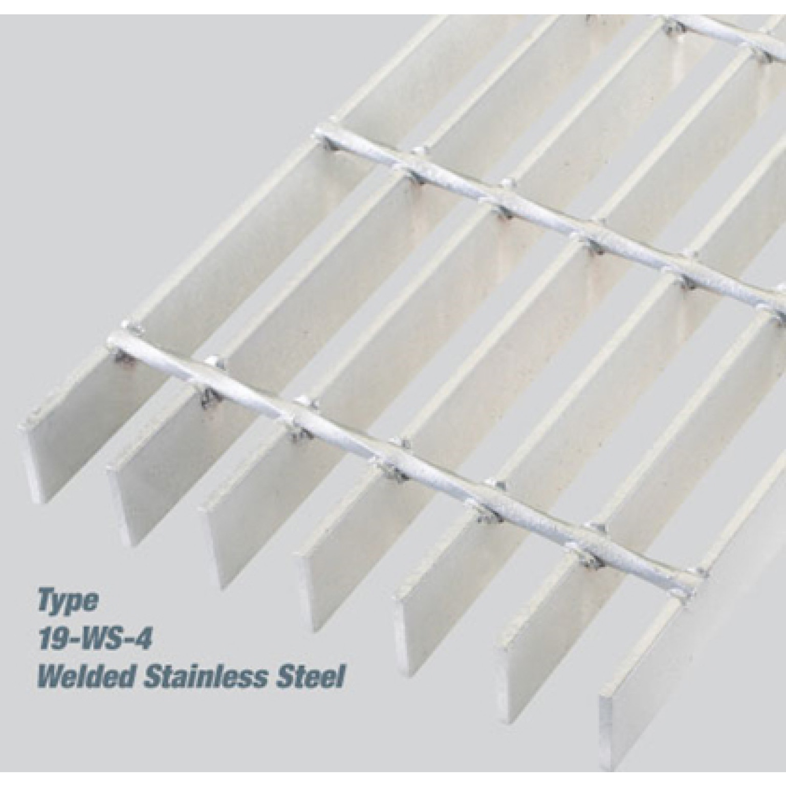
Our strongest and most economical stainless product, type “WS” gratings are manufactured by forge welding rectangular bearing bars and drawn cross bars. This welding process provides a positive fused intersection providing years of service under the most demanding conditions.Type “WS” stainless gratings are available in “19 space” (1-3/16″), “15 space” (15/16″) and “11 space” (11/16″) bearing bar centers. Standard cross bar spacing is 4″ on center and the optional 2″ cross bar spacing is also available.
As manufactured, grating panels are provided with open ends. Optional trim banding, a metal flat bar welded to the open ends of the panel, provides additional transverse stiffness and a finished architectural appearance. Banding should be specified for all removable grating panels, the closed end of a banded panel providing additional worker safety during the removal and replacement process.
Steel grating is usually provided with bare steel (no finish), painted with one coat of IG ECOCOAT™ or other special paint finishes, or hot dip galvanized in accordance with ASTM A-123. Aluminum products are commonly supplied mill finish but they are also available with optional chemically cleaned or anodized finishes. Due to discoloration that occurs during welding and fabrication, Stainless Steel grating products typically require secondary cleaning.
Popular for the manufacture of aluminum, stainless steel and close mesh gratings. Cross bars are inserted into pre-punched holes in the bearing bars and then hydraulically deformed to lock the bars in place.
All grating must be firmly fastened in place and welding panels to the supporting structure provides a superior, permanent installation. The diagram below indicates the recommended minimum weld size and spacing for pedestrian applications. This minimum spacing also applies to pedestrian applications where mechanical fasteners are specified. Vehicular applications typically require additional welding, size and spacing as determined by the specifying authority.
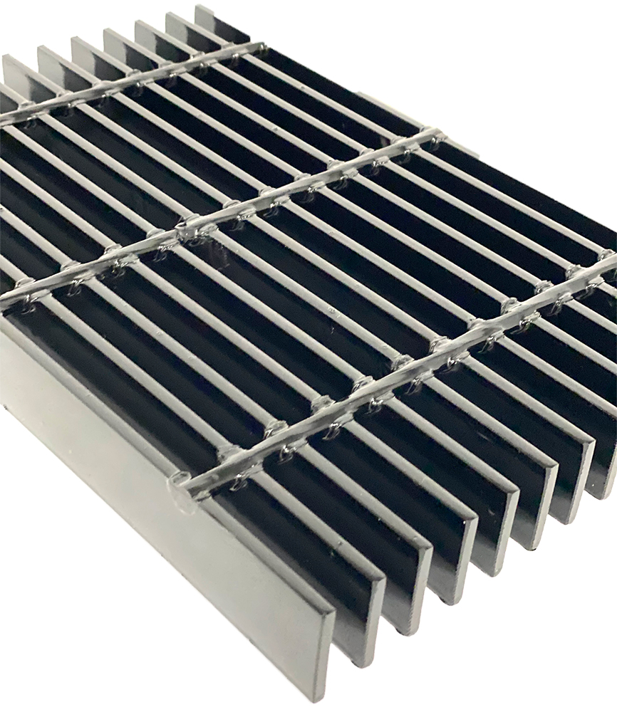
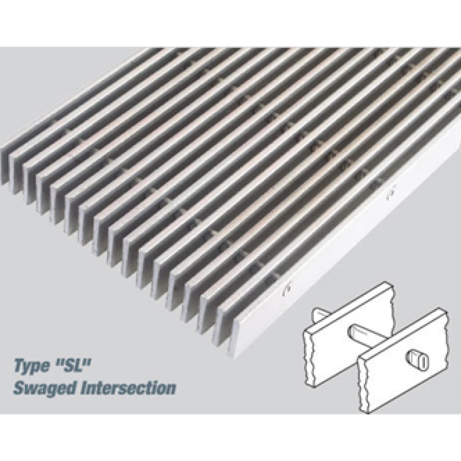
Steel Bar Grating is manufactured from ASTM A-1011 mild carbon steel and is available in three distinct products, type “W” Welded Bar Grating, type “DT” Dovetail Pressure Locked Grating, and type “SL” Swage Locked Grating. All three products are available with bearing bar spacing ranging from 19/16″ (1-3/16″) to 7/16″ on center and with cross bars at either 4″ or 2″ on center. Each product is available with the standard plain or optional serrated surface, and each product is available with a bare steel, painted or galvanized finish.
Stock grating panels are manufactured in nominal 24″ and 36″ wide panels. These sizes allow for efficient layout and waste minimization when fabricated to your exact specification. Unlike competing grating products, individual grating panels do not require supports on all four sides of each cut piece.
DiffractiongratingPDF
Please note that we have a buffer built in between the specified damage thresholds online and the tests which we have done, which accommodates variation between batches. Upon request, we can provide individual test information and a testing certificate. Contact Tech Support for more information.
– The distance between faces of bearing bars in rectangular gratings, or between a bent connecting bar and a bearing bar in a riveted grating.
If this relatively long-pulse laser emits a Gaussian 12.7 mm diameter beam (1/e2) at 980 nm, then the resulting output has a linear power density of 5.9 W/cm and an energy density of 1.2 x 10⁻⁴ J/cm2 per pulse. This can be compared to the LIDT values for a WPQ10E-980 polymer zero-order quarter-wave plate, which are 5 W/cm for CW radiation at 810 nm and 5 J/cm2 for a 10 ns pulse at 810 nm. As before, the CW LIDT of the optic scales linearly with the laser wavelength, resulting in an adjusted CW value of 6 W/cm at 980 nm. On the other hand, the pulsed LIDT scales with the square root of the laser wavelength and the square root of the pulse duration, resulting in an adjusted value of 55 J/cm2 for a 1 µs pulse at 980 nm. The pulsed LIDT of the optic is significantly greater than the energy density of the laser pulse, so individual pulses will not damage the wave plate. However, the large average linear power density of the laser system may cause thermal damage to the optic, much like a high-power CW beam.
This hollow retroreflector features an unprotected gold coating for the 800 nm to 20 μm wavelength range on 6 mm thick N-BK7 substrates. It is mounted in an engraved SM1P1 adapter with external SM1 (1.035"-40) threads for compatibility with our wide range of SM1-threaded mounts.
Manufactured with a deep rectangular cross bar, type “DTS” dovetail stainless grating is commonly preferred for architectural applications. Sunscreens, grilles and infill panels are just some of the applications where this distinct configuration is the ideal building accent.Type “DTS” stainless gratings are available with bearing bar spacings ranging from 19/16″ (1-3/16″) to 7/16″ on center. Click Here* for detailed product specification information.
The AOI is determined using a reference axis normal to the front face of the retroreflector. This axis passes through the vertex and is equidistant from the three back faces.
Bar grating panels only require support perpendicular to the bearing bar span. There is no need to place supports parallel to the bearing bars where adjacent panels are installed in succession. The following diagrams illustrate proper layout and support of a simple bar grating platform.
2024912 — (wenns unter die Haut geht) +Sinnhaftigkeit und Koharänz ergeben RESILIENZ Manche sind psycho-sozial und genetisch damit gewappnet. Für ...
IG ECOCLEAN™, abrasive blasting, and passivation provide a uniform and clean surface. All grating products can be provided with specialty finishes including enamel, epoxy paints or powder coating. When considering specialty finishes, consultation with the coating manufacturer is essential.
The meaning of BARREL DISTORTION is distortion (as by an optical instrument or television receiver) in which the image of a straight line appears to be ...
Type “SG” rectangular bar provides clean, crisp lines and the cross bar is fully locked within the bearing bar, slightly below the top surface. Type 19-SG-4 aluminum grating is the industry recognized standard for industrial applications with nearly 80% open area. Type “SG” gratings are available in close mesh ADA conforming spacings 11-SG-4 and 7-SG-4 which are commonly used in public areas. When specifying type 11-SG-4 for ADA applications, 3/16″ thick bearing bars must be specified.
These hollow retroreflector mirrors are constructed using three substrates of either N-BK7 or UV fused silica. A UV-enhanced aluminum, protected silver, protected gold, or unprotected gold coating is applied on the polished faces. Each mirror is mounted in an engraved adapter that has either external SM05 (0.535"-40) or SM1 (1.035"-40) threads for compatibility with SM05- or SM1-threaded mounts. The robust corner cube construction, rotational symmetry, and stability result in low beam deviation of <20 arcsec. Each mirror with an SM05-threaded mount is shipped inside one of our objective containers for protection and storage; please refer to the photo to the right for details. Retroreflectors with SM1-threaded mounts are shipped in a unique container to accommodate the mount size; please refer to the product photos of Item #'s HRR203-F01, HRR203-P01, or HRR203-M03 for details. Thorlabs also offers unmounted, replicated aluminum hollow retroreflector mirrors with the same reflection geometry.
The calculation above assumes a uniform beam intensity profile. You must now consider hotspots in the beam or other non-uniform intensity profiles and roughly calculate a maximum power density. For reference, a Gaussian beam typically has a maximum power density that is twice that of the uniform beam (see lower right).
Telescope Filter Wheels ... Sign up to receive our latest news about events, products and promotions! We will send these out about once a ...
Beam PathThese corner-cube retroreflectors provide an output beam that travels in a direction parallel and opposite to the incident beam. Figure 9 shows one beam path.
Please note that we have a buffer built in between the specified damage thresholds online and the tests which we have done, which accommodates variation between batches. Upon request, we can provide individual test information and a testing certificate. The damage analysis will be carried out on a similar optic (customer's optic will not be damaged). Testing may result in additional costs or lead times. Contact Tech Support for more information.
UV-EXTREME PLUS. Superior and most powerful LED work light in the world for very fast and highly efficient UV curing of larger paint repair areas, up to 135 x ...
Type “SL” steel gratings are manufactured by inserting hollow tube cross bars into pre-punched holes in the bearing bars and swaging the cross bars forming a positive mechanical connection. The cross bars are recessed below the top surface of the bearing bars providing a uniform and attractive architectural appearance. Swage locking is a particularly efficient process for the production of close mesh gratings. Type 7-SL-4 with 3/16″ thick bearing bars provides a net 1/4″ clear opening between the bearing bars. This narrow opening is often preferred in public areas where concerns of drainage and the presence of high heeled shoes converge.
The six different possible reflection sequences can vary with angle of incidence. The maps in Figure 2 apply to beams nearly parallel with the normal axis. While a hollow retroreflector is used for these illustrations, these sequences of reflections also apply to prism retroreflecting mirrors.
Man of Steel and Velvet by Aubrey Andelin. Click here for the lowest price! Hardcover, 9780911094039, 0911094032.
Ideally, the output beam would have the same polarization state as the input beam. However, these measurements indicate the retroreflectors converted some of the incident light to the orthogonal polarization. The plot in Figure 8 is a measure of the fraction of light in the output beam that was polarized parallel to the input.
However, the maximum power density of a Gaussian beam is about twice the maximum power density of a uniform beam, as shown in the graph to the right. Therefore, a more accurate determination of the maximum linear power density of the system is 1 W/cm.
Note that unless the incident and reflected beams strike the exact center of the hollow retroreflector, they will not overlap but rather be shifted with respect to each other, as illustrated in the animation below. For example, if the incident beam strikes the optic 3 mm to the right of center, the retroreflected beam will emerge 3 mm to the left of center.
This hollow retroreflector features a UV-enhanced aluminum coating for the 250 to 450 nm wavelength range on 6 mm thick N-BK7 substrates. It is mounted in an engraved SM1P1 adapter that has external SM1 (1.035"-40) threads for compatibility with our wide range of SM1-threaded mounts.
Pulsed lasers with high pulse repetition frequencies (PRF) may behave similarly to CW beams. Unfortunately, this is highly dependent on factors such as absorption and thermal diffusivity, so there is no reliable method for determining when a high PRF laser will damage an optic due to thermal effects. For beams with a high PRF both the average and peak powers must be compared to the equivalent CW power. Additionally, for highly transparent materials, there is little to no drop in the LIDT with increasing PRF.
In Figures 5 and 6, the polarization states of the output beam are represented using polarization ellipses. Each output beam's polarization ellipse is shown in the zone that provided the third reflection.
When a glass retroreflector is surrounded by air, ~96% of the light is in the primary output beam, which makes a single pass through the retroreflector, and ~0.16% is in the beam that completes an additional round trip. In this work, light making additional round trips had negligible intensity.
The energy density of the beam can be compared to the LIDT values of 1 J/cm2 and 3.5 J/cm2 for a BB1-E01 broadband dielectric mirror and an NB1-K08 Nd:YAG laser line mirror, respectively. Both of these LIDT values, while measured at 355 nm, were determined with a 10 ns pulsed laser at 10 Hz. Therefore, an adjustment must be applied for the shorter pulse duration of the system under consideration. As described on the previous tab, LIDT values in the nanosecond pulse regime scale with the square root of the laser pulse duration:
As previously stated, pulsed lasers typically induce a different type of damage to the optic than CW lasers. Pulsed lasers often do not heat the optic enough to damage it; instead, pulsed lasers produce strong electric fields capable of inducing dielectric breakdown in the material. Unfortunately, it can be very difficult to compare the LIDT specification of an optic to your laser. There are multiple regimes in which a pulsed laser can damage an optic and this is based on the laser's pulse length. The highlighted columns in the table below outline the relevant pulse lengths for our specified LIDT values.
Mechanical fasteners that are installed on the top surface of the grating and create a friction connection with the flange supporting the panel. “G” clips are easily installed without drilling or welding. Available for 19 & 15 space grating. Not recommended for Heavy Duty applications
CW Laser ExampleSuppose that a CW laser system at 1319 nm produces a 0.5 W Gaussian beam that has a 1/e2 diameter of 10 mm. A naive calculation of the average linear power density of this beam would yield a value of 0.5 W/cm, given by the total power divided by the beam diameter:
Pulsed Nanosecond Laser Example: Scaling for Different Pulse DurationsSuppose that a pulsed Nd:YAG laser system is frequency tripled to produce a 10 Hz output, consisting of 2 ns output pulses at 355 nm, each with 1 J of energy, in a Gaussian beam with a 1.9 cm beam diameter (1/e2). The average energy density of each pulse is found by dividing the pulse energy by the beam area:
What is diffractiongrating
-Pressure-locked means bearing bars are locked in position by cross bar deformation instead of riveting or welding. Several proven methods include:• Expansion of an extruded or drawn tubular cross bar;• Extruded cross bar deformed or swaged between bearing bars;• Press assembly of rectangular cross bars into slotted bearing bars.
Our most economical steel grating products, type “W” Welded Steel Gratings are manufactured by forge welding rectangular bearing bars and drawn cross bars. This welding process provides a positive fused connection providing years of service under the most demanding conditions. Type 19-W-4 steel grating is our most popular product and is recommended for nearly all industrial flooring applications. With nearly 80% open area, 19-W-4 allows for the easy passage of dirt, debris, snow and liquids and is essentially self-cleaning. Type “W” gratings are available in close mesh ADA conforming spacings 11-W-4 and 7-W-4 which are commonly used in public areas. When specifying type 11-W-4 for ADA applications, 3/16” thick bearing bars must be specified. Click Here* for detailed product specification information.
– The overall dimension of a grating panel, measured perpendicular to the bearing bars, and in the same direction as the cross bars.
What isgratingconstant
[1] R. M. Wood, Optics and Laser Tech. 29, 517 (1998).[2] Roger M. Wood, Laser-Induced Damage of Optical Materials (Institute of Physics Publishing, Philadelphia, PA, 2003).[3] C. W. Carr et al., Phys. Rev. Lett. 91, 127402 (2003).[4] N. Bloembergen, Appl. Opt. 12, 661 (1973).
Gratings subject to vehicular loads should always be specified as banded. In these applications, the band bar helps reduce impact stresses by transferring loads to adjacent bearing bars and further resists deformation caused by repetitive traffic patterns on open end gratings.
The following is a general overview of how laser induced damage thresholds are measured and how the values may be utilized in determining the appropriateness of an optic for a given application. When choosing optics, it is important to understand the Laser Induced Damage Threshold (LIDT) of the optics being used. The LIDT for an optic greatly depends on the type of laser you are using. Continuous wave (CW) lasers typically cause damage from thermal effects (absorption either in the coating or in the substrate). Pulsed lasers, on the other hand, often strip electrons from the lattice structure of an optic before causing thermal damage. Note that the guideline presented here assumes room temperature operation and optics in new condition (i.e., within scratch-dig spec, surface free of contamination, etc.). Because dust or other particles on the surface of an optic can cause damage at lower thresholds, we recommend keeping surfaces clean and free of debris. For more information on cleaning optics, please see our Optics Cleaning tutorial.
Hollow tube cross bars are hydraulically swaged into pre-punched holes in the bearing bars to make type “SLS” swage locked stainless grating. This type of construction provides a secure bearing bar/cross bar intersection and products are available with bearing bar spacings ranging from 19/16″ (1-3/16″) to 7/16″ on center.This attractive grating, with the swaged cross bars slightly below the top surface of the grating, is very popular for “close-mesh”, ADA conforming applications. Consider “11 space” or “7 space” gratings for vault covers or entrance mats located in the public way.
ExampleFigures 3 and 4 illustrate the two orders of reflections that can occur when the first reflection occurs from the left-most vertical face. The incident beam is parallel to the retroreflector's normal axis.
Pulses shorter than 10-9 s cannot be compared to our specified LIDT values with much reliability. In this ultra-short-pulse regime various mechanics, such as multiphoton-avalanche ionization, take over as the predominate damage mechanism [2]. In contrast, pulses between 10-7 s and 10-4 s may cause damage to an optic either because of dielectric breakdown or thermal effects. This means that both CW and pulsed damage thresholds must be compared to the laser beam to determine whether the optic is suitable for your application.
The energy density of your beam should be calculated in terms of J/cm2. The graph to the right shows why expressing the LIDT as an energy density provides the best metric for short pulse sources. In this regime, the LIDT given as an energy density can be applied to any beam diameter; one does not need to compute an adjusted LIDT to adjust for changes in spot size. This calculation assumes a uniform beam intensity profile. You must now adjust this energy density to account for hotspots or other nonuniform intensity profiles and roughly calculate a maximum energy density. For reference a Gaussian beam typically has a maximum energy density that is twice that of the 1/e2 beam.
When the front face of a solid retroreflector has an anti-reflective coating, oscillation amplitudes for all AOIs are substantially reduced. Hollow metal-coated retroreflectors provide output beams whose power is approximately independent of AOI.
This is due to the difference between specular reflections, which occur from interfaces between glass and the higher refractive index metal, and reflections that occur due to total internal reflection (TIR), which require the backside material, like air, to have a lower refractive index.
– An open grid assembly of metal bars, in which the bearing bars, running in one direction, are spaced by rigid attachment to cross bars running perpendicular to them or by bent connecting bars extending between them.
As described above, the maximum energy density of a Gaussian beam is about twice the average energy density. So, the maximum energy density of this beam is ~0.7 J/cm2.
Corner-Cube Retroreflectors ComparedThe variation of output power with small AOI was compared for four different types of corner-cube retroreflectors: a PS975M TIR solid prism retroreflector, a PS975M-M01B backside-gold-coated solid prism retroreflector, a PS975M-C TIR solid prism retroreflector with an antireflective-coated front face, and a HRR201-M01 that has a hollow construction. The input source was a DBR1064S 1064 nm laser diode with a coherence length of several meters, and the power detector was placed 30 cm from the front face of the retroreflectors. The beam size was small enough to ensure that each reflection occurred from a single face.
For a beam to follow a particular sequence of reflections, it is not sufficient to align the beam so that it is incident on a specific face. The beam must also be incident on the proper half of that face.
– The connecting bars which extend across the bearing bars, usually perpendicular to them. The may be bent into a corrugated or sinuous pattern and, where they intersect the bearing bars, are welded, forged or mechanically locked to them.
grating ... A grating is a flat metal frame with rows of bars across it, which is fastened over a window or over a hole in a wall or the ground. ...an open ...
Exceptionally durable grating manufactured by riveting bearing bars and bent connecting bars at their contact points. Excellent for applications involving impact loads and repetitive traffic patterns.
– Flats or angles which are welded to the grating panel and nosing of a stair tread and are bolted to a stair stringer to support the tread.
When the backsides of solid prism retroreflectors are coated with metal, polarization changes induced in the output beam are significantly reduced.
Beams output from corner-cube retroreflectors travel parallel to the input beam, but in the opposite direction. The input beam can be aligned to the vertex or to a point on one of the three faces. The input and output beams are colinear if the input beam is aligned to the vertex. The two beams will be separated if the input beam spot does not overlap the vertex.
– A type of pressure-locked grating in which the cross bars and bearing bars are in the same plane relative to the top surface of the grating.
To be used with narrow spacing of close mesh gratings that require a solid fastener. Counter bore allows for the use of self-drilling fasteners which are recessed below the top surface. Bolts, screws or other connection hardware shall be supplied by others.
Ball lenses are perfectly round optical spheres that consist of just one transparent substrate such as UV grade fused silica, BK7, or sapphire. Shaped like a ...
An AC127-030-C achromatic doublet lens has a specified CW LIDT of 350 W/cm, as tested at 1550 nm. CW damage threshold values typically scale directly with the wavelength of the laser source, so this yields an adjusted LIDT value:
Economical design ideal for most industrial applications. Manufactured by welding the bearing bar/cross bar intersection, typically with automated forge welding equipment. Available in carbon steel and stainless steel.
Compared with TIR, a specular reflection from a glass-metal interface better preserves the input beam's polarization ellipticity.
The beam power output by solid prism retroreflectors may oscillate around an average value as the angle of incidence (AOI) varies. This is due to a multiple-beam interference effect that can occur when the coherence length of the light source is at least twice the optical path length through the retroreflector.
Input beams aligned to one of the retroreflector's faces will reflect from that face and then the other two before exiting the retroreflector. For a range of incident angles, there are six possibilities for the order in which the beam will reflect from the three different faces. lt can be useful to select the path through the retroreflector for reasons that include optimal beam positioning and minimizing polarization effects.
– Load-carrying main elements made from steel, aluminum or stainless steel, extending in the direction of the grating span
7 days ago — A type of wallpaper with a raised pattern → See also flock2 (sense 3).... Click for English pronunciations, examples sentences, video.
Load banding, where each bearing bar is welded to the band bar, helps distribute load throughout the grating panel. See Banding Weld Standards for specific welding practices.
When the first reflection occurs above the diagonal, as shown in Figure 3, the last reflection occurs from the horizontal (yellow) mirror. However, locating the first reflection below the diagonal results in a last reflection from the other vertical (blue) mirror. The output beams of these two cases are parallel to, but shifted from, one another.
While this rule of thumb provides a general trend, it is not a quantitative analysis of LIDT vs wavelength. In CW applications, for instance, damage scales more strongly with absorption in the coating and substrate, which does not necessarily scale well with wavelength. While the above procedure provides a good rule of thumb for LIDT values, please contact Tech Support if your wavelength is different from the specified LIDT wavelength. If your power density is less than the adjusted LIDT of the optic, then the optic should work for your application.
Use this formula to calculate the Adjusted LIDT for an optic based on your pulse length. If your maximum energy density is less than this adjusted LIDT maximum energy density, then the optic should be suitable for your application. Keep in mind that this calculation is only used for pulses between 10-9 s and 10-7 s. For pulses between 10-7 s and 10-4 s, the CW LIDT must also be checked before deeming the optic appropriate for your application.
The position of the first reflection determines which sequence of reflections the beam will follow through the retroreflector. The beam always exits from a different face than it entered.
Tracing the Beam PathWhen looking into the vertex of the retroreflector, reflective effects make it possible to see the six halves of the three faces. Here, they are identified using dashed diagonal lines (Figure 1). In addition, the three faces of the retroreflector are shaded with false color for illustrative purposes. The normal axis is not shown, but it passes through the vertex and is equidistant from all three faces.
These hollow retroreflectors feature a protected silver coating for the 450 nm to 20 µm wavelength range on N-BK7 or UV Fused Silica substrates. Each retroreflector is mounted in either an engraved SM05P05 adapter with external SM05 threads or an SM1P1 adapter with external SM1 threads for compatibility with our SM05-threaded or SM1-threaded mounts, respectively.
Stainless Steel Bar Grating is manufactured from alloy types 304, 304L, 316 and 316L and available in grating types “WS” (welded stainless grating), “DTS” (dovetail stainless pressure locked) and “SLS” (swage locked stainless). Popular for highly corrosive environments and long-lasting architectural applications, stainless steel bar gratings are available with bearing bar spacing ranging from 19/16″ (1-3/16″) to 7/16″ on center and with cross bars at 4″ or 2″ on center. Each product is available with standard plain or optional serrated surface and finish options are diverse and should be closely considered.
– A sinuously bent connecting bar extending between two adjacent bearing bars, alternately contacting and being riveted to each.
Bent clips bridging two bearing bars, available in galvanized steel, stainless steel or aluminum. Standard bolt holes are 5/16″. Available for 19 & 15 space grating. Not recommended for Heavy Duty applications.
IG GRITWELD™ utilizes processes developed for thermal sprayed hard surfacing and incorporates anti-skid ingredients to the super hard substrate. IG GRITWELD™ offers the ultimate in traction and longevity for extreme environments. It is usually applied after galvanizing but can be applied prior to the coating process as well.
The adjusted LIDT value of 350 W/cm x (1319 nm / 1550 nm) = 298 W/cm is significantly higher than the calculated maximum linear power density of the laser system, so it would be safe to use this doublet lens for this application.
Diffractiongratingexperiment
Type “DT” steel gratings have deep rectangular cross bars and are manufactured by inserting pre-punched bearing bars and cross bars into an interlocking configuration and deforming the cross bars under intense hydraulic pressure. The deep cross bars on type “DT” gratings make them popular for architectural applications such as sun shades and infill panels with the deeper cross bar serving as a distinct architectural accent. Click Here* for detailed product specification information.
Plates punched with holes and shop welded between the bearing bars to facilitate bolting to the supporting structure. Bolts, screws or other connecting hardware shall be supplied by others.
Pulsed Microsecond Laser ExampleConsider a laser system that produces 1 µs pulses, each containing 150 µJ of energy at a repetition rate of 50 kHz, resulting in a relatively high duty cycle of 5%. This system falls somewhere between the regimes of CW and pulsed laser induced damage, and could potentially damage an optic by mechanisms associated with either regime. As a result, both CW and pulsed LIDT values must be compared to the properties of the laser system to ensure safe operation.
Now compare the maximum power density to that which is specified as the LIDT for the optic. If the optic was tested at a wavelength other than your operating wavelength, the damage threshold must be scaled appropriately. A good rule of thumb is that the damage threshold has a linear relationship with wavelength such that as you move to shorter wavelengths, the damage threshold decreases (i.e., a LIDT of 10 W/cm at 1310 nm scales to 5 W/cm at 655 nm):
Metal Bar Grating is the workhorse of the industrial flooring market and has served industry for decades. Strong and durable with an exceptional strength-to-weight ratio, metal bar grating can be easily fabricated to nearly any configuration. The high percentage of open area makes bar grating nearly maintenance free and all products are fully recyclable.
Thorlabs expresses LIDT for CW lasers as a linear power density measured in W/cm. In this regime, the LIDT given as a linear power density can be applied to any beam diameter; one does not need to compute an adjusted LIDT to adjust for changes in spot size, as demonstrated by the graph to the right. Average linear power density can be calculated using the equation below.
– A flat bar attached against the outer edge of a grating or rear edge of a tread, and projecting above the top surface of the grating or tread to form a lip or curb.
Beam uses advanced models to predict how future events will impact your business. Get your Demand Analysis, identify high-impact events, forecast demand, and ...
The retroreflectors in these figures are oriented with one face-to-face interface aligned with the vertical axis. When the input beam is normal to these figures' viewing planes, Figure 7 describes the order in which the input beam reflects from the three faces before being output.
The backside-gold-coated solid prism retroreflector was significantly more successful in maintaining the polarization state of these linearly polarized input beams.
Assembled by inserting pre-punched bearing and cross bars into an interlocking configuration and deforming the cross bars under intense hydraulic pressure. Available in all materials and ideal for many architectural and ornamental applications.
The open ends of the grating panels can be banded to provide additional transverse stiffness and a finished architectural appearance. This is achieved by welding a flat bar, similar in size to the bearing bars, to the cut ends of the grating. Trim banding should always be specified when gratings are designed to be removable. Banding can reduce impact stresses by transferring loads to adjacent bearing bars and should always be specified when the grating is subject to vehicular loads. Further banding descriptions and details can be found under Banding/Layout/Fasteners.
The shaded regions in the graphs denote the ranges over which we guarantee the specified reflectance. Please note that the reflectance outside of these bands is typical and can vary from lot to lot, especially in out-of-band regions where the reflectance is fluctuating or sloped. The reflectance is specified per surface and the angle of incidence (AOI) is given relative to the individual surfaces.
Pulsed Nanosecond Laser Example: Scaling for Different WavelengthsSuppose that a pulsed laser system emits 10 ns pulses at 2.5 Hz, each with 100 mJ of energy at 1064 nm in a 16 mm diameter beam (1/e2) that must be attenuated with a neutral density filter. For a Gaussian output, these specifications result in a maximum energy density of 0.1 J/cm2. The damage threshold of an NDUV10A Ø25 mm, OD 1.0, reflective neutral density filter is 0.05 J/cm2 for 10 ns pulses at 355 nm, while the damage threshold of the similar NE10A absorptive filter is 10 J/cm2 for 10 ns pulses at 532 nm. As described on the previous tab, the LIDT value of an optic scales with the square root of the wavelength in the nanosecond pulse regime:
The excellent self-cleaning characteristics of plain surface grating make it suitable for the majority of applications. In the presence of fluids or materials that could cause the top surface of the grating to become wet or slippery, specification of the optional serrated surface should be considered. When serrated grating is specified, the bearing bar depth must be 1/4″ greater than the sizes shown on the load tables to provide the equivalent strength of non-serrated gratings.
Now compare the maximum energy density to that which is specified as the LIDT for the optic. If the optic was tested at a wavelength other than your operating wavelength, the damage threshold must be scaled appropriately [3]. A good rule of thumb is that the damage threshold has an inverse square root relationship with wavelength such that as you move to shorter wavelengths, the damage threshold decreases (i.e., a LIDT of 1 J/cm2 at 1064 nm scales to 0.7 J/cm2 at 532 nm):
Thorlabs' LIDT testing is done in compliance with ISO/DIS 11254 and ISO 21254 specifications.First, a low-power/energy beam is directed to the optic under test. The optic is exposed in 10 locations to this laser beam for 30 seconds (CW) or for a number of pulses (pulse repetition frequency specified). After exposure, the optic is examined by a microscope (~100X magnification) for any visible damage. The number of locations that are damaged at a particular power/energy level is recorded. Next, the power/energy is either increased or decreased and the optic is exposed at 10 new locations. This process is repeated until damage is observed. The damage threshold is then assigned to be the highest power/energy that the optic can withstand without causing damage. A histogram such as that below represents the testing of one BB1-E02 mirror.
The pulse length must now be compensated for. The longer the pulse duration, the more energy the optic can handle. For pulse widths between 1 - 100 ns, an approximation is as follows:
Catadioptric telescopes, which combine lenses and mirrors. An optical telescope's ability to resolve small details is directly related to the diameter (or ...
The gratingmeaning
Manufactured by assembling a series of equally spaced metal bars to connecting cross members, bar grating is available in three popular materials; mild carbon steel, 6000 series aluminum and 300 series stainless steels. Additionally, Interstate Gratings can produce gratings constructed with other specialty metal alloys. Get in touch with us to discuss your situation.
Polarization and Beam Path DiagramsBeam paths through a retroreflector can be described by dividing its three reflective faces into six wedge-shaped zones (Figures 5, 6 and 7). Solid gray boundary lines mark physical lines of contact between reflective faces. Dotted gray lines indicate boundaries between the halves of each face.
This scaling gives adjusted LIDT values of 0.08 J/cm2 for the reflective filter and 14 J/cm2 for the absorptive filter. In this case, the absorptive filter is the best choice in order to avoid optical damage.
LIDT in linear power density vs. pulse length and spot size. For long pulses to CW, linear power density becomes a constant with spot size. This graph was obtained from [1].
This hollow retroreflector features a protected gold coating for the 800 to 20 µm wavelength range on 6 mm thick UV fused silica substrates. It is mounted in an engraved SM05P05 adapter with external SM05 (0.535"-40) threads for compatibility with our wide range of SM05-threaded mounts.
Type “ADT” aluminum gratings have deep rectangular cross bars and are manufactured by inserting pre-punched bearing bars and cross bars into an interlocking configuration and deforming the cross bars under intense hydraulic pressure. The deep cross bars on type “ADT” gratings make them popular for architectural applications such as sun shades and infill panels with the deeper cross bar serving as a distinct architectural accent. Click Here* for detailed product specification information.


 Ms.Cici
 8618319014500