Neutral Density Filters - neutral density filter meaning
Field curvaturechart
It has been shown that, if you have a doublet lens, made of two lenses, one a converging lens of focal length \(f_1\) and refractive index \(n_1\), and the other a diverging lens of focal length \(f_2\) and refractive index \(n_2\), curvature of field will be least if \(\frac{1}{n_1f_2}+\frac{1}{n_2f_2}=0\). For example if you have two glasses, of refractive indices \(n_1\) = 1.51 and the other of refractive index \(n_2\) = 1.67, and you want to make a doublet lens of focal length 100 cm, what should be the focal lengths of the two components of the doublet if you want to minimize curvature of field?

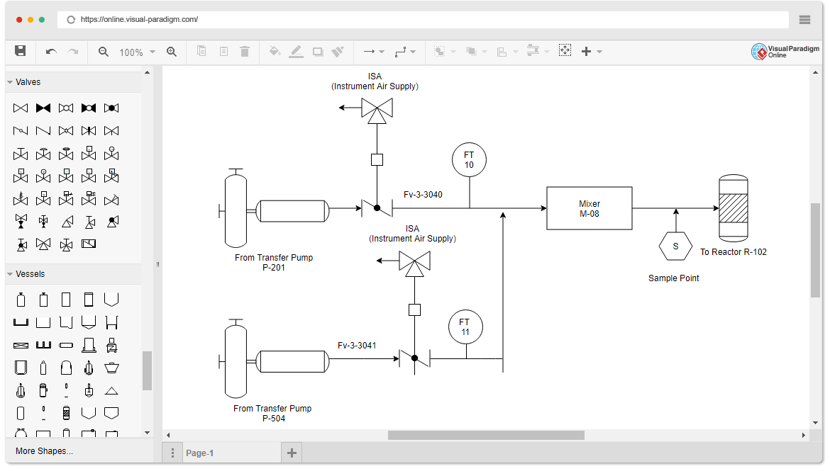
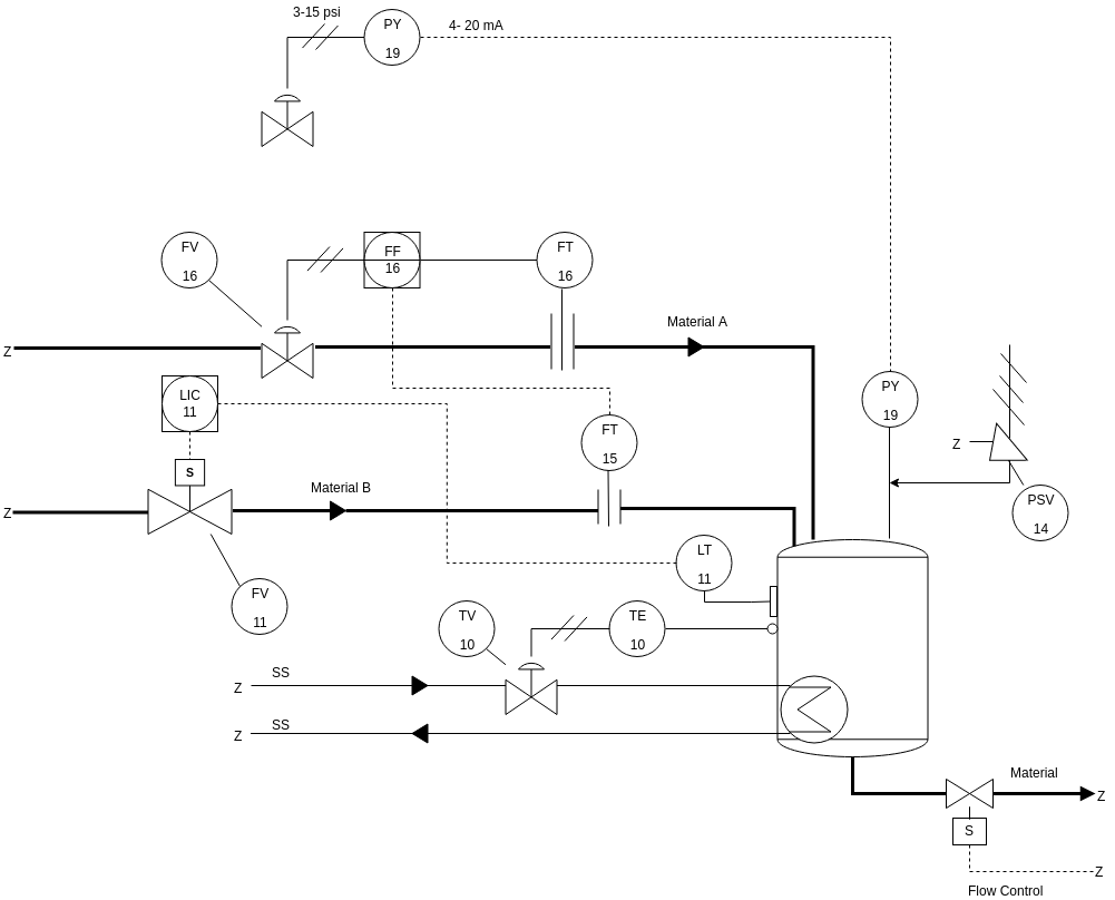
With Visual Paradigm Online, you don't need to start each P&ID from scratch because a rich set of piping templates is ready for you. Followings are some of these P&ID templates. Click the image to preview, or click the edit button to start editing. More P&ID examples are available inside the P&ID diagram editor.
Field curvaturelens
Want to draw piping and instrumentation diagrams? Visual Paradigm's P&ID tool features a handy diagram editor that allows you to draw P&ID diagrams, industrial diagrams, and schematics quickly and easily. The P&ID diagram software comes with a rich set of high-quality P&ID symbols for you to create different kinds of P&ID diagrams. Without a doubt, Visual Paradigm Online is the best P&ID software to create schematics for the process industry.
Field curvatureaberration
This doesn’t matter a great deal in a telescope designed merely for looking through, since the eye can rapidly accommodate for slightly different image distance, but it obviously matters in a photographic telescope. One effective way of dealing with this problem, particularly if your detector is a flexible film, is to shape the filmholder so that the film fits along the Petzval surface. This is often done, for example, with Schmidt astronomical telescopes.
Field curvatureexample
In designing a lens or lens system, the problems of astigmatism and curvature of field are often closely related. For example a meniscus lens tends to suffer from astigmatism, and there is a focal surface for the tangential image, and a focal surface for the sagittal image, and the tangential and sagittal surfaces curve in opposite senses. With luck, or more likely with some careful design, the surface (C) for the loci of the circles of least confusion is between the tangential (T) and sagittal (S) surfaces and is approximately planar (Figure IV.15).
This page titled 4.5: Curvature of Field is shared under a CC BY-NC 4.0 license and was authored, remixed, and/or curated by Jeremy Tatum via source content that was edited to the style and standards of the LibreTexts platform.
Alas, life is not as simple as that, and light doesn’t generally come to a focus in a focal plane, but rather in a curved focal surface (sometimes called the Petzval surface), as in Figure IV.14.
The LibreTexts libraries are Powered by NICE CXone Expert and are supported by the Department of Education Open Textbook Pilot Project, the UC Davis Office of the Provost, the UC Davis Library, the California State University Affordable Learning Solutions Program, and Merlot. We also acknowledge previous National Science Foundation support under grant numbers 1246120, 1525057, and 1413739. Legal. Accessibility Statement For more information contact us at info@libretexts.org.
Field curvaturephotography
Suppose we have a lens that we have managed to correct for (or at least to minimize) spherical aberration, astigmatism and coma, say by a combination of choosing the right shape of the lens and not going too far off-axis. (I.e. we might close the lens to an aperture of \(f/11\) rather than opening it up to \(f/5.6\).) Nothing that we know about refraction and lenses and mirrors tells us that that light coming in at different angles to the axis forms point images conveniently situated in a plane, as illustrated hopefully in Figure IV.13.
Answer: The lenses need to satisfy \(\frac{1}{n_1f_1}+\frac{1}{n_2f_2}=0 \) and \(\frac{1}{f_1}+\frac{1}{f_2}=\frac{1}{f}\). It’s probably easier to work in terms of powers rather than focal lengths, so we have to solve \(1.67 P_1 + 1.51 P_2 = 0\) and \(P_1 + P_2 =0.01\). This gives \(P_1 = −0.094375\) cm−1 and \(P_2 = +0.104375\) cm−1, or \(f_1\) = 10.60 cm and \(f_2\) = 9.58 cm. You will then have to design the lenses so that the faces of the two lenses that are in contact have the same radius of curvature, and we leave that to the reader.


 Ms.Cici
 8618319014500