
MTF of an image sensor - lens mtf measurement
Sealed Air · Jiffylite Self-Seal Bubble Mailer, #0, Barrier Bubble Air Cell Cushion, Self-Adhesive Closure, 6 x 10, Brown Kraft, 25/CT · Bubble Wrap Cushion ...
After the preliminary tests, the number of repeats required to achieve a 100µm deep engraving was extrapolated linearly for each fluence setting and is between 20 and 120 passes.
The removal rate is defined as the volume, which is removed per time unit, here in mm³ per minute. This criterion allows a comparison of all different laser parameters of the test series and provides information on the efficiency and process speed.
VIS-NIR: Our visible/near-infrared broadband anti-reflection coating is specially optimized to yield maximum transmission (>99%) in the near-infrared.
Reflective coatingroof
AR coatings are designed so that the relative phase shift between the beam reflected at the upper and lower boundaries of a thin film is 180°. Destructive interference between the two reflected beams occurs, which cancels out both beams before they exit the surface (Figure 2). The optical thickness of the optical coating must be an odd integer multiple of $\tfrac{\lambda}{4}$, where $ \small{\lambda} $ is the design wavelength or wavelength being optimized for peak performance in order to achieve the desired path difference of $\tfrac{\lambda}{2}$ between the reflected beams. When achieved, this will lead to the cancellation of the beams. The index of refraction of a thin film $ \small{\left( n_f \right)} $ needed for complete cancelation of the reflected beams can be found by using the refractive indices of the incident medium $ \small{\left( n_0 \right)} $ and the substrate $ \small{\left( n_s \right)} $.
Telecom-NIR: Our telecom/near-infrared is a specialized broadband AR coating for popular telecommunications wavelengths from 1200 – 1600nm.
VIS 0° and VIS 45°: VIS 0° (for 0° angle of incidence) and VIS 45° (for 45° angle of incidence) provide optimized transmission for 425 – 675nm, reducing average reflection to 0.4% and 0.75% respectively. VIS 0° AR coating is preferred over MgF2 for visible applications.
The Laser equipment used for this study are a picosecond laser (λ = 1064nm, Pmax = 40W at 1MHz, pulse duration = 8ps) in combination with a Novanta Squirrel, 11mm analog 2D scan head equipped with a telecentric F-Theta lens with a focal length of 80mm. The resulting beam caustic was analyzed with a Primes MicroSpotMonitor, which measured a focal diameter of about 50µm and a beam quality of the entire setup of M² = 1.18 (see Figure 2).
The results on this paper show that the fluence is a critical parameter for achieving high-quality surface structuring. However, both criteria do have specific individual optima within the fluence curves that depend on the various laser, scanner and material combinations. It is further shown that the process is limited by quality, and not by average laser power. Therefore, process improvements can usually not be achieved by higher average power lasers unless the scanning system can provide much higher speeds at equal accuracy. However, the tests performed effectively show that optimization for individual laser, scanner and material combinations for specific application requirements can and should always be done. In the present case, a fluence of 0.6J/cm², applied at 200kHz, ~18W average power and 10 burst pulses was ideal to meet the required quality.
To keep the parameter range manageable, the following laser parameters were varied: laser repetition rate (1000kHz and 200kHz), laser power (100% and 50%) and number of burst pulses (1,2,5,10). At a pulse repetition rate of 1000kHz, a pulse energy of 40µJ is delivered resulting in a maximum fluence of 3J/cm². Using just 50% of power the fluence decreases to 1.6J/cm². Changing the laser frequency to 200kHz results in a roughly four times higher pulse energy delivered by the laser (170µJ). Therefore, the resulting maximum fluence is 12J/cm² at 100% power at 200kHz. Additional levels of fluences beside those at 100% and 50% are generated by inserting the burst mode of the laser with 1,2,5, and 10 pulses per burst (see figure 3). This way the pulse energy is split up into the number of burst pulses leading to a decreased fluence value. In total the pulse energy stays the same within a single burst. The series of burst pulses is emitted at the seeder frequency, which is 30MHz.
Feb 16, 2021 — F10 Fresnel Attachment 45° ... When used with the F10 Fresnel Attachment the 600d Pro had an output of 87,500 lx (8130 fc). That was 9.88% less ...
The surface roughness as a function of the fluence is presented in Figure 5. The measured surface roughness falls within a range of 1.5µm to 5µm, with an extreme of up to 30µm for the combination of 1000kHz and 100% laser power at high numbers of burst pulses. It can be assumed that this is a result of a high pulse overlap and strong melting of the material, that causes the melt to solidify in a random peak and valley structure, leading to increased surface roughness. To mitigate this issue, increasing the scanning speed can help, while this approach is not part of the current study. Overall, the graphs indicate that the surface roughness is heavily influenced by laser and scanner parameters, emphasizing the importance of finding the optimal set of parameters to achieve the desired smoothness.
Reflective coatingSpray
By adjusting laser power and pulse overlap, the surface microstructure is manipulated which creates a certain macro appearance. As this requires even finer surface structures than before, a fluence of 0.6J/cm² is used for the following color schemes.
Zhenjiang Ideal Optical was founded in 2008.From its inception focus was placed solely on lenses.Since then the company has evolved in to a factory that.
Broadband anti-reflection (BBAR) coatings are designed to improve transmission over a much wider waveband. They are commonly used with broad-spectrum light sources and lasers with multiple-harmonic generation. BBAR coatings typically do not achieve reflectivity values quite as low as V-coats but are more versatile because of their wider transmission band. In addition to being applied to transmissive optical components including lenses and windows, AR coatings are also used on laser crystals and nonlinear crystals to minimize reflections, as Fresnel reflections occur where air and the crystal meet.1
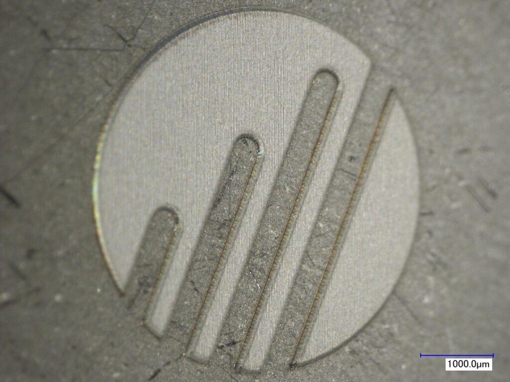
While individual application requirements in this industry vary immensely, a common request is to engrave a detailed logo with a size of 1-10mm² about 50µm deep or even up to a full millimeter (deep engraving) into a metal (see Figure 1). At the same time, the feature details of such logos often need to be in the range of 50µm and to appear with a sharp contrast from the base material. This request for high-contrast can be solved by a fine microstructure of the engraved surface in the range of 1-5µm which then selectively reflects light and therefore lets the material shine in a specific color. Typically, no post processing is desired, hence high-quality, burr free marking is required. Figure 8, towards the end of this paper shows some black, gray and white examples of these colors.
Feb 11, 2015 — Adafruit Industries, Unique & fun DIY electronics and kits Reflective Infrared IR Optical Sensor with 470 and 10K Resistors : ID 2349 - This ...
anti-reflective coating是什么
Anti-reflection V-coats are a type of AR coating designed to increase transmission over a very narrow waveband centered at a specified design wavelength (DWL). This coating type is called “V-coat” because the curve of the transmission versus wavelength forms a “V,” with a minimum at the DWL. V-coats are ideal for obtaining maximum transmission when using single-frequency, small linewidth lasers, or narrow full width-half max (FWHM) light sources.1 V-coats typically have a reflectivity of less than 0.25% at the DWL. However, the reflection curve for the coating locally has a nearly parabolic shape and the reflectivity is significantly higher at wavelengths besides the DWL (Figure 3).
Reflective coatingglasses
Edmund Optics offers all TECHSPEC® transmissive optics with a variety of anti-reflection (AR) coating options that vastly improve the efficiency of the optic by increasing transmission, enhancing contrast, and eliminating ghost images. Most AR coatings are also very durable, with resistance to both physical and environmental damage. For these reasons, the vast majority of transmissive optics include some form of anti-reflection coating. When specifying an AR coating to suit your specific application, you must first be fully aware of the full spectral range of your system. While an AR coating can significantly improve the performance of an optical system, using the coating at wavelengths outside the design wavelength range could potentially decrease the performance of the system.
Features · Modular Zoom Lens System for Machine Vision and Other Imaging Applications · 6.5X System Provides Magnifications from 0.09 to 18.0 (Core Lens has a ...
Figure 4 shows the removal rates of the different laser settings as a function of the resulting fluence. Comparing 100% of average power with 50% at 1000kHz (blue) the removal rate is in a range from 1.4mm³/min to 3.5mm³/min. At the lower repetition rate of 200kHz the values range from 0.8mm³/min to 3.7mm³/min. At 1000kHz and 50% laser power the removal rate first increases at lower fluences, reaches a maximum, and then decreases again. At 200kHz the same behavior can be assumed but is not visible in the data generated. Overall, there is evidence that fluences of 1J/cm² or more, lead to a decreased removal rate. The physical background of this behavior is out of scope of this paper.
For the analysis of the created test samples a KEYENCE VK-X210 laser scanning microscope and a KEYENCE VW-9000 High Speed Microscope were used to identify the surface roughness (Ra) and the engraving depth.
A simple square with edge length of 3mm x 3mm was chosen as a test pattern which is filled by lines of a defined hatch distance. In the first tests the number of passes is limited to 10, later that number will be extrapolated to a depth of 100µm. For the purpose of comparability, the marking speed was fixed at 1m/s.
Reflective coatingpaint
Alternatively, for samples which scatter light, absorbance may be defined as "the negative logarithm of one minus absorptance, as measured on a uniform sample".
anti-reflectioncoating
Laser engraving has become a widely used method for marking and decorating various materials within the jewelry and watch industry due to its high precision, flexibility, and non-contact nature. Compared to traditional mechanical engraving techniques, laser engraving provides several benefits, such as better control over the depth and width of the engraving, the color appearance of the engraved area, the ability to create more complex designs, and virtually no wear of the engraving tool. Additionally, the laser process can be optimized to not produce chips or debris, making it cleaner and less prone to damage of precious materials like metals, gemstones or ceramics.
Table 1 shows the reflectivity and guaranteed laser-induced damage threshold (LIDT) for Edmund Optics’ standard laser V-coats.
As within all industrial applications, process time and process quality matter. For this type of deep engraving application, it is necessary to achieve a good removal rate of several mm³ per minute and simultaneously create a corner radius of less than 50µm with a final surface roughness of just a few micrometers with defined structure. To achieve a sweet spot of these requirements, the laser energy density per pulse, also known as fluence, is a crucial parameter as it affects the engraving quality, removal rate, and surface roughness. Therefore, the optimization of the fluence is essential to achieve the desired engraving results in terms of removal rate and quality. This white paper aims to investigate the effect of laser fluence on the quality of deep engraving on steel using a 40W average power picosecond laser.
Importing Reynaers aluminum products, Big Glass Openings is the leading manufacturer in Canada and the North Eastern United States. High-end windows and ...
UV-AR and UV-VIS: Ultraviolet coatings are applied to our UV fused silica lenses and UV fused silica windows to increase their coating performance in the ultraviolet region.
Because reflectivity increases rapidly as the wavelength of the source moves further away from the DWL, optical components with V-coats are meant for use at exactly or very close to the intended DWL of the coating. An interesting characteristic of V-coats is that the shape of their transmission curves is semi-periodic such that the reflectivity reaches a local minimum at harmonics of the DWL (e.g. $ \tfrac{\lambda_0}{2} $ or $ \tfrac{\lambda_0}{4} $) that are not as optimized for reflectivity as at the DWL. V-coats are usually comprised of only two coating layers. Simple V-coats can consist of a single layer with a thickness of a $ \tfrac{\lambda}{4} $, but more layers may be required to adjust the bandwidth or if a coating material with an appropriate index of refraction is not available. Multilayer coatings may also compensate for different angles of incidence, but are more complicated and tend to have larger bandwidths. If the thickness of the V-coat layers is incorrect, the reflectivity of the coating increases and the DWL changes. V-coats from Edmund Optics typically achieve minimum reflectivities significantly less than 0.25%, but all standard V-coats have specified reflectivities of <0.25% at the DWL. This allows for small shifts in the DWL from coating tolerances.
NIR I and NIR II: Our near-infrared I and near-infrared II broadband AR coatings offer exceptional performance in near-infrared wavelengths of common fiber optics, laser diode modules, and LED lights.
Opticalcoating
Both criteria, roughness, and removal rate, show better results at lower fluences, except the lowest fluence in this test series. The removal rate got its maximum peek at a fluence of 12J/cm², but the corresponding roughness of 5µm is comparatively high which is often not acceptable.
Within the first series of tests the achievable removal rate and surface roughness is examined after 10 passes of the defined hatching pattern and with all combinations of laser parameters previously described. This step is extremely important as too high of a surface roughness cannot be compensated for in the final surface structuring step.
In figure 7 the removal rate (blue) and surface roughness (green) are both shown as a function of the fluence at a setting of 200kHz and 100% and 50%. Similarly as before, the lowest fluences are achieved by applying 10 burst pulses, while the higher fluences are achieved with a single pulse.
In conclusion, our study provides insights into the laser ablation process for achieving high-quality surface structuring on stainless steel. Our findings can be used to optimize the laser parameters for specific application requirements and to further develop the laser ablation process for other materials and applications.
Our Applications Testing Labs offer application and proof-of-concept testing to OEMs, system integrators, material manufacturers, processors, and end-users of automated machinery. Novanta Application Engineers are laser processing experts, and understand the parameters that will ensure successful, efficient laser processing. Using laser and beam steering equipment from well- known Novanta brands, our Application Engineers will determine the key product parameters and processing know-how to achieve the desired results.
$\tfrac{\lambda}{4}$ MgF2: The simplest AR coating used is $ \tfrac{\lambda}{4} $ MgF2 centered at 550nm (with an index of refraction of 1.38 at 550nm). MgF2 coating is ideal for broadband use though it gives varied results depending upon the glass type involved.
May 24, 2022 — Advanced Photonix UV Enhanced Silicon Photodiode offers a high-performance, cost-effective solution for any requirement.
No. Under no circumstances should anyone use compressed air to clean off clothing or any part of the body. Although many people know using compressed air to ...
Laser engraving is a widely used method for marking a variety of materials, from vehicle parts and toolmaking over electromechanics, to jewelry and watches. The laser process allows for fine structures and high flexibility in shaping the engraved design, while also enabling a contactless process. Short pulse lasers, such as the picosecond laser used in this study, enable engraving on a wide range of materials with low heat impact, making it suitable even for temperature-sensitive electronic parts. This paper investigates the impact of laser energy density (fluence) on the quality of deep engraving on steel for jewelry and watch applications, with a focus on removal rate and surface quality. Tests were performed using a 40W average power picosecond laser, varying laser repetition rate, power, and number of burst pulses. The results provide insights into the efficiency of the laser engraving process at different fluence levels.
The preceding engraving step creates a smooth surface with a roughness of 0.5µm. After finishing the surface, the roughness ranges from 1.7µm to 2.0µm, depending on the requested appearance.
polarization. Polarization refers to the orientation of oscillations in a transverse wave, such as light waves, radio waves, or other electromagnetic waves. In ...
Due to Fresnel reflection, as light passes from air through an uncoated glass substrate approximately 4% of the light will be reflected at each interface. This results in a total transmission of only 92% of the incident light, which can be extremely detrimental in many applications (Figure 1). Excess reflected light reduces throughput and can lead to laser-induced damage in laser applications. Anti-reflection (AR) coatings are applied to optical surfaces to increase the throughput of a system and reduce hazards caused by reflections that travel backwards through the system and create ghost images. Back reflections also destabilize laser systems by allowing unwanted light to enter the laser cavity. AR coatings are especially important for systems containing multiple transmitting optical elements. Many low-light systems incorporate AR coated optics to allow for efficient use of light.
In this study, we investigated the laser ablation process of stainless steel to achieve high-quality surface structuring for jewelry and watch applications. We analyzed the effect of laser and scanner parameters on the removal rate and surface roughness of the machined surface.
For jewelry and watch industries, the customer often wants to have a certain appearance, like black, white, opaque, or shiny. All of these can be achieved with an additional finishing step after the requested depth is reached if at this point the surface roughness is not too high (Ra < ~5 µm).
antireflectivecoating中文
Novanta is uniquely positioned to solve even the most complex challenges for OEMs, system integrators, and end-use customers seeking to advance their manufacturing processes with high precision laser systems. With some of the most well-known brands in the industry and in-country application and service support, Novanta delivers reliable, precise, and durable components and sub-systems.
For deep engraving more than the initially tested 10 passes are required, which has a further impact on the resulting surface roughness. While the removal rates at 100% and 1000kHz are very good, the generated surface roughness is unacceptably high to achieve the required surface finish. Therefore, the parameters at 200kHz provide the best ablation rate and quality combination which are used for further tests with more passes and higher engraving depth.
The second evaluation criterion is the surface roughness Ra (Roughness Average), which provides insight into the quality of the machined surface. In this study, achieving a very smooth surface is crucial as it aligns with the target market’s requirements of typical 2µm or lower.
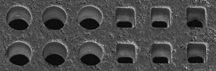
Figure 6 shows images of the worst and best result of surface roughness. The left images represent the extreme value of 30µm of roughness achieved at 1000kHz, that leads to a random peak and valley structure with a high burr at the edge. The other example shows a smooth surface with a roughness of 1.5µm. There is also a smooth transition on the edge of the machined surface without burr.
Edmund Optics offers all TECHSPEC® lenses with an optional single-layer, dielectric anti-reflection (AR) coating to reduce surface reflections. In addition, custom single-layer, multi-layer, V, and 2V coatings are available for both our off-the-shelf and large volume custom orders. View Custom Optical Lens Coatings for information.


 Ms.Cici
 8618319014500