
Microscope Objective Lenses for Industry - microscope lense
The blazed grating features geometries similar to the transmission and reflection gratings discussed thus far; the incident angle () and th order reflection angles () are determined from the surface normal of the grating. However, the significant difference is the specular reflection geometry is dependent on the blaze angle, , and NOT the grating surface normal. This results in the ability to change the diffraction efficiency by only changing the blaze angle of the diffraction grating.
Diffraction grating formulaA Level
The blaze wavelength is one of the three main characteristics of the blazed grating. The other two, shown in Figure 3, are , the groove or facet spacing, and , the blaze angle. The blaze angle is the angle between the surface structure and the surface parallel. It is also the angle between the surface normal and the facet normal. Note that Figure 3 also defines the direction of the "blaze arrow"; this arrow is visibly marked on one edge of all Thorlabs' blazed transmission gratings.
Resolving Power:The resolving power of a grating is a measure of its ability to spatially separate two wavelengths. It is determined by applying the Rayleigh criteria to the diffraction maxima; two wavelengths are resolvable when the maxima of one wavelength coincides with the minima of the second wavelength. The chromatic resolving power (R) is defined by R = λ/Δλ = n*N, where Δλ is the resolvable wavelength difference, n is the diffraction order, and N is the number of grooves illuminated. Due to their low groove density, Echelle gratings provide high resolving power.
Caution for Gratings with Surface Grooves:The surface of a diffraction grating with surface grooves can be easily damaged by fingerprints, aerosols, moisture or the slightest contact with any abrasive material. Gratings should only be handled when necessary and always held by the sides. Latex gloves or a similar protective covering should be worn to prevent oil from fingers from reaching the grating surface. Solvents will likely damage the grating's surface. No attempt should be made to clean a grating other than blowing off dust with clean, dry air or nitrogen. Scratches or other minor cosmetic imperfections on the surface of a grating do not usually affect performance and are not considered defects. Conversely, volume phase holographic gratings can be cleaned using standard optics cleaning procedures and have high durability.
Diffraction gratingexperiment
There are many reasons why your optical integrator may recommend bandpass filters; they are a mainstay in countless optoelectronic devices, are at the forefront of datacom filter solutions, and present many opportunities to reduce the footprint and design complexity of your systems.
Bandpass filters are optical filters that only let a selected range of frequencies through. Bandpass filters are used for many optical applications in telecommunications, satellite communications and data transfer for light modulation. This article will explore some common use cases of bandpass filters and how they allow users’ applications to obtain “more signal, with less background”.
Blaze Wavelength:Ruled gratings have a sawtooth groove profile created by sequentially etching the surface of the grating substrate. As a result, they have a sharp peak efficiency around their blaze wavelength. Holographic gratings are harder to blaze, and tend to have a sinusoidal groove profile resulting in a less intense peak around the design wavelength. Applications centered around a narrow wavelength range could benefit from a ruled grating blazed at that wavelength.
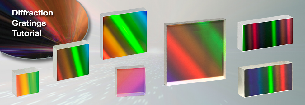
Reflective grating master copies are made by depositing a metallic coating on an optic and ruling parallel grooves in the surface. Thorlabs' reflective gratings are made of epoxy and/or plastic imprints from a master copy, in a process called replication. In all cases, light is reflected off of the ruled surface at different angles corresponding to different orders and wavelengths. All of Thorlabs' ruled reflective diffraction gratings exhibit a sawtooth profile, also known as blazed, while our reflective holographic diffraction gratings exhibit a sinusoidal profile. For more information, please refer to the Gratings Tutorial tab.
Diffraction grating formulaDerivation
Canada's best selection of full-frame fixed focal length wide angle lenses at Vistek Canada Featuring SEL FE 35mm f/1.4 GM E-Mount Lens 35mm f/1.4 DG DN Art ...
Lençol plano SLEEP NUMBER ESSENCIAL ALGODÃO BRANCO QUEEN SIZE, CONTAGEM DE 300 FIOS ... Lençol ...
Polarization Dependence:Surface gratings that have high groove densities also have an issue with polarization dependent loss, often with significantly lower efficiency when exposed to parallel- versus perpendicularly-polarized light. Volume phase holographic gratings are designed for applications that require low polarization dependent loss at higher spatial frequencies.
Diffraction grating formulaWhat is n
Another very common diffractive optic is the reflective grating. A reflective grating is traditionally made by depositing a metallic coating on an optic and ruling parallel grooves in the surface. Reflective gratings can also be made of epoxy and/or plastic imprints from a master copy. In all cases, light is reflected off of the ruled surface at different angles corresponding to different orders and wavelengths. An example of a reflective grating is shown in Figure 2. Using a similar geometric setup as above, the grating equation for reflective gratings can be found:
The Littrow configuration angle, , is dependent on the most intense order ( = 1), the design wavelength, , and the grating spacing . It is easily shown that the Littrow configuration angle, , is equal to the blaze angle, , at the design wavelength. The Littrow / blaze angles for all Thorlabs' Blazed Gratings can be found in the grating specs tables.
Diffraction gratings, either transmissive or reflective, can separate different wavelengths of light using a repetitive structure embedded within the grating. The structure affects the amplitude and/or phase of the incident wave, causing interference in the output wave. In the transmissive case, the repetitive structure can be thought of as many tightly spaced, thin slits. Solving for the irradiance as a function wavelength and position of this multi-slit situation, we get a general expression that can be applied to all diffractive gratings when = 0°,
where both and are positive if the incident and diffracted beams are on opposite sides of the grating surface normal, as illustrated in the example in Figure 1. If they are on the same side of the grating normal, must then be considered negative.
Thorlabs offers two types of transmission gratings: ruled and volume phase holographic. The ruled transmission gratings are created by scratching or etching a transparent substrate with a repetitive, parallel structure, creating areas where light can scatter. These gratings have a sawtooth diffraction profile and are made of epoxy and/or plastic imprints from a master copy, in a process called replication. Our volume phase holographic diffraction gratings consist of a dichromated gelatin (DCG) film between two glass substrates. These gratings have a sinusoidal wave diffraction pattern written on the DCG film using a laser setup. For more information, please refer to the Gratings Tutorial tab.
Oct 3, 2013 — You can get lost in the above physiology. The simpler answer is about 20 fps. Whenever strobing stops and persistence of vision takes over to ...
One popular style of grating is the transmission grating. The sample diffraction grating with surfaces grooves shown in Figure 1 is created by scratching or etching a transparent substrate with a repetitive series of narrow-width grooves separated by distance . This creates areas where light can scatter.
where is positive and is negative if the incident and diffracted beams are on opposite sides of the grating surface normal, as illustrated in the example in Figure 2. If the beams are on the same side of the grating normal, then both angles are considered positive.
The DCG film is taken through multiple quality control steps to ensure it performs up to standard and then cut into the desired size. The film is sealed between two glass covers to prevent degradation of the material. Since the DCG film is contained between two glass substrates, VPH gratings have high durability and long lifetimes, as well as easy maintenance compared to other gratings that can be easily damaged.
While blazed gratings offer extremely high efficiencies at the design wavelength, they suffer from periodic errors, such as ghosting, and relatively high amounts of scattered light, which could negatively affect sensitive measurements. Holographic gratings are designed specially to reduce or eliminate these errors. The drawback of holographic gratings compared to blazed gratings is reduced efficiency.
A high-quality bandpass filter can block all but a narrow range of frequencies and therefore eliminate contributions from nearby channels. Wavelength division multiplexing has become one of the technologies of choice for transferring large amounts of data and providing network infrastructures for large corporations. The technology allows for more efficient networks, but wavelength division multiplexing relies on bandpass filters to ensure that only the desired light colors pass through.
Telecom and satcom bandpass filters are used to filter the bandwidth of signals to select the signal of interest from the background. In modern fiber optic networks, it has become common to use designs that involve multiplexing of channels. Wavelength-division multiplexers help improve the efficiency of the transfer of information but the proximity of multiple channels risks cross-talk and potential degradation of the integrity of the data being transferred.
by KM Hampson · 2021 · Cited by 173 — Adaptive optics (AO) is a technique that corrects for optical aberrations. It was originally proposed to correct for the blurring effect of ...
Holographic gratings are made from master gratings by similar processes to the ruled grating. The master holographic gratings are typically made by exposing photosensitive material to two interfering laser beams. The interference pattern is exposed in a periodic pattern on the surface, which can then be physically or chemically treated to expose a sinusoidal surface pattern. An example of a holographic grating is shown in Figure 9.
In photography these are also called F-stops. F/ = f / D. Problem 1 – An astronomer wants to design a telescope that takes up the least amount of.
At Iridian Spectral, we consider ourselves experts in bandpass filter design. We are uniquely positioned to help advise you on the best optical solution for your specifications. If we believe bandpass filters are suitable for your application, we can then craft custom optical filters based on your individual requirements.
The incident light impinges on the grating at an angle , as measured from the surface normal. The light of order exiting the grating leaves at an angle of , relative to the surface normal. Utilizing some geometric conversions and the general grating expression (Eq. 1) an expression for the transmissive diffraction grating can be found:
Diffraction grating formulafor maxima
Bandpass filters are used for so many applications because they allow for shaping and controlling the wavelengths that pass through. The filtering process within the bandpass filter provides for the selective blocking of unwanted wavelengths. This filtering is beneficial in many spectroscopic applications where scattered light may contaminate a spectrum or cause saturation of a detector, or there may be residual fundamental wavelengths from some frequency conversion process.
The high selectivity for a given central wavelength is crucial for satcom where high transmittance in the signal band, but good blocking of all other wavelengths is essential. Many satcom instruments also require very large diameter windows compared to other applications and need blocking with steep edges to maximize the isolation of particular channels and prevent cross-communication. Often, solar rejection bandpass filters are required at the input of a satcom optical communication port, transmitting the SWIR telecom bands while blocking the background solar radiation, improving signal quality, and additionally preventing solar induced heating within the satellite.
The first issue with using higher order diffraction patterns is solved by using an Echelle grating, which is a special type of ruled diffraction grating with an extremely high blaze angle and relatively low groove density. The high blaze angle is well suited for concentrating the energy in the higher order diffraction modes. The second issue is solved by using another optical element: grating, dispersive prism, or other dispersive optic, to sort the wavelengths/orders after the Echelle grating.
Songs · "Hot n Cold", by Katy Perry · "Hot n Cold", by Albert Collins 1965 · "Hot & Cold", by SM Town from 2022 Winter SM Town: SMCU Palace, 2022 · "Hot and ...
Please note that dispersion is based solely on the number of grooves per mm and not the shape of the grooves. Hence, the same grating equation can be used to calculate angles for holographic as well as ruled blazed gratings.
The 1.5mm allen key is an essential tool in various industries, known for its precision and ability to fit into tight spaces. This tool falls under the category ...
Both the reflective and transmission gratings suffer from the fact that the zeroth order mode contains no diffraction pattern and appears as a surface reflection or transmission, respectively. Solving Eq. 2 for this condition, = , we find the only solution to be =0, independent of wavelength or diffraction grating spacing. At this condition, no wavelength-dependent information can be obtained, and all the light is lost to surface reflection or transmission.
Infrared WindowsInfrared windows are used to remove the risk to thermographers by ensuring that they are never exposed to energized electrical equipment while ...
Diffraction gratingdefinition
For further information about gratings and selecting the grating right for your application, please visit our Gratings Tutorial.
known as the grating equation. The equation states that a diffraction grating with spacing will deflect light at discrete angles (), dependent upon the value λ, where is the order of principal maxima. The diffracted angle, , is the output angle as measured from the surface normal of the diffraction grating. It is easily observed from Eq. 1 that for a given order , different wavelengths of light will exit the grating at different angles. For white light sources, this corresponds to a continuous, angle-dependent spectrum.
The Littrow configuration refers to a specific geometry for blazed gratings and plays an important role in monochromators and spectrometers. It is the angle at which the grating efficiency is the highest. In this configuration, the angle of incidence of the incoming and diffracted light are the same, = , and > 0 so
The desired grating pattern is comprised of a repetitive series of lines separated by distance . The fringe planes for transmission gratings are perpendicular to the plane of the plate as seen in Figure 8, allowing any frequency of light to pass through the plate. Diffraction occurs as incoming light crosses through the DCG film. Therefore, the three major factors that determine performance are film thickness, bulk index (the average index of refraction between Bragg planes), and index modulation (the difference of index of refraction between the Bragg planes). The incident light enters the grating at an angle of , as measured from the surface normal. The light of order exiting the grating leaves at an angle of , relative to the surface normal. The grating expression mentioned above can be used to calculate diffraction angles for volume phase holographic gratings since dispersion is based on the line density. The quality of the grating is determined by the fringe contrast, with a poor fringe contrast resulting in low efficiency or no grating at all.
Raman spectroscopy is one example of a technique where a bandpass filter can help ensure the laser illumination light is monochromatic (since the resultant Raman scattered light is observed as a shift relative to the illumination light) thus reducing unwanted background. There are also specific polymerase chain reaction (PCR) band pass filters designed to help discriminate the fluorescence signal produced by one probe from another, which is essential for identifying specific genetic material.
Diffraction grating formulawavelength
Figure 6 illustrates the specific case where = 0°, hence the incident light beam is perpendicular to the grating surface. In this case, the 0th order reflection also lies at 0°. Utilizing Eqs. 3 and 4, we can find the grating equation at twice the blaze angle:
Unlike traditional gratings, volume phase holographic (VPH) gratings do not have surface grooves. Instead, VPH gratings consist of a dichromated gelatin (DCG) film between two glass substrates. These VPH gratings are designed to reduce the periodic errors that can occur in blazed gratings. Surface gratings with high groove density also have an issue with polarization dependent loss. These unique transmission gratings deliver high first-order diffraction peak efficiency, low polarization dependence, and uniform performance over broad bandwidths.
Diffraction grating formulaexample
The blazed grating, also known as the echelette grating, is a specific form of reflective or transmission diffraction grating designed to produce the maximum grating efficiency in a specific diffraction order. This means that the majority of the optical power will be in the designed diffraction order while minimizing power lost to other orders (particularly the zeroth). Due to this design, a blazed grating operates at a specific wavelength, known as the blaze wavelength.
The specular reflection from the blazed grating is different from the flat surface due to the surface structure, as shown in Figure 5. The specular reflection, , from a blazed grating occurs at the blaze angle geometry. This angle is defined as being negative if it is on the same side of the grating surface normal as . Performing some simple geometric conversions, one finds that
A bandpass filter modulates the incident spectrum of the light by only allowing a fixed amount of bandwidth at a given frequency to pass through. The exact ‘sharpness’ of the filtering, amount of bandwidth transmitted and the central frequency are all dependent on the design of the particular bandpass filter.
The 0th order reflection from a blazed grating is shown in Figure 4. The incident light at angle is reflected at for = 0. From Eq. 3, the only solution is = –. This is analogous to specular reflection from a flat surface.
It is easily observed that the wavelength dependent angular separation increases as the diffracted order increases for light of normal incidence (for = 0°, increases as increases). There are two main drawbacks for using a higher order diffraction pattern over a low order one: (1) a decrease in efficiency at higher orders and (2) a decrease in the free spectral range, , defined as:
Efficiency:Ruled gratings generally have a higher efficiency than holographic gratings. Holographic grating tend to have a lower efficiency but a broader effective wavelength range. The efficiency of ruled gratings may be desirable in applications such as fluorescence excitation and other radiation-induced reactions.
A convex mirror is made by coating a spherical surface so that reflection occurs at the outside. The center of this sphere is called center (C) of the mirror ...
These include the linear magnification, numerical aperture value, optical corrections, microscope body tube length, the type of medium the objective is ...
Stray Light:Due to a difference in how the grooves are made, holographic gratings have less stray light than ruled gratings. The grooves on a ruled grating are machined one at a time which results in a higher frequency of errors. Holographic gratings are made through a lithographic process, which generally creates smoother grating masters free of tool marks. Replicants made from these masters exhibit less stray light. Applications such as Raman spectroscopy, where signal-to-noise is critical, can benefit from the limited stray light of the holographic grating.
This issue can be resolved by creating a repeating surface pattern, which produces a different surface reflection geometry. Diffraction gratings of this type are commonly referred to as blazed (or ruled) gratings. More information about this can be found in the section below.


 Ms.Cici
 8618319014500