
Microscope Calculations: Field of View, Depth ... - numerical aperture and resolution
Sphericalaberration correction
All necessary code and instructions for running the axial correction macro are provided in the Supplementary Software and Box 1.
Thank you for visiting nature.com. You are using a browser version with limited support for CSS. To obtain the best experience, we recommend you use a more up to date browser (or turn off compatibility mode in Internet Explorer). In the meantime, to ensure continued support, we are displaying the site without styles and JavaScript.
Ghosh, S. & Preza, C. Three-dimensional block-based restoration integrated with wide-field fluorescence microscopy for the investigation of thick specimens with spatially variant refractive index. J. Biomed. Opt. 21, 46010 (2016).
I am aware that some new cameras (DSLRs, DSCs, SLDs) have in-camera corrections for these distortions, and also there are some tools to correct it in post processing (e.g., PTlens) but what is the exact procedure used in the correction process? Does the correction process work in Raw Bayer domain, or after some color conversion to YCbCr?
Stack Exchange network consists of 183 Q&A communities including Stack Overflow, the largest, most trusted online community for developers to learn, share their knowledge, and build their careers.
The idea for calculating axial distortion correction factors as described in this tutorial was conceived by D.S.R. and J.W.L. E.E.D. and D.S.R. carried out experiments and analyzed data. D.S.R., J.W.L. and E.E.D. wrote the manuscript. All authors contributed to editing the final manuscript.
Visser, T. D., Oud, J. L. & Brakenhoff, G. J. Refractive-index and axial distance measurements in 3-D microscopy. Optik 90, 17–19 (1992).
Publisher’s note Springer Nature remains neutral with regard to jurisdictional claims in published maps and institutional affiliations.
Schmidt, N. C., Kahms, M., Huve, J. & Klingauf, J. Intrinsic refractive index matched 3D dSTORM with two objectives: comparison of detection techniques. Sci. Rep. 8, 13343 (2018).
Sphericalaberration in a lens
Hell, S., Reiner, G., Cremer, C. & Stelzer, E. H. K. J. Microsc. 169, 391–405, (1993): https://onlinelibrary.wiley.com/doi/abs/10.1111/j.1365-2818.1993.tb03315.x
Engelbrecht, C. J. & Stelzer, E. H. Resolution enhancement in a light-sheet-based microscope (SPIM). Opt. Lett. 31, 1477–1479 (2006).

Sphericalaberration photography
Sheppard, C. J., Gu, M., Brain, K. & Zhou, H. Influence of spherical aberration on axial imaging of confocal reflection microscopy. Appl. Opt. 33, 616–624 (1994).
Hell, S., Reiner, G., Cremer, C. & Stelzer, E. H. K. Aberrations in confocal fluorescence microscopy induced by mismatches in refractive-index. J. Microsc. 169, 391–405 (1993).
I am aware that barrel distortion occurs more in wide-angle lenses, wherein straight lines near edges of the frame curve outwards. Is it pincushion distortion when lines curve inward, and in what conditions (what types of lenses, etc.) does pincushion distortion occur?
Renier, N. et al. iDISCO: a simple, rapid method to immunolabel large tissue samples for volume imaging. Cell 159, 896–910 (2014).
Sphericalaberration example
Carlsson, K. The influence of specimen refractive-index, detector signal integration, and nonuniform scan speed on the imaging properties in confocal microscopy. J Microsc.-Oxford 163, 167–178 (1991).
Visser, T. D. et al. Optik 90, 17–19 (1992): https://www.researchgate.net/publication/285251956_Refractive_index_and_axial_distance_measurements_in_3-D_microscopy
Sphericalaberration and chromatic aberration
Any pointers (especially for question 2) would be useful, as I am trying to implement one post process for this type of correction.
We thank S. Piccinotti and L. Rubin for providing organoid samples. We thank the Harvard Center for Biological Imaging for infrastructure and support. J.W.L. was supported by the following funding sources: National Institutes of Health grants P50 MH094271, U24 NS109102, and U19 NS104653 and Department of Defense MURI award GG008784.
What issphericalaberration in Physics
Sphericalaberration in mirrors
Patwary, N., King, S. V., Saavedra, G. & Preza, C. Reducing effects of aberration in 3D fluorescence imaging using wavefront coding with a radially symmetric phase mask. Opt. Express 24, 12905–12921 (2016).
Sphericalaberration formula
Preza, C. & Conchello, J. A. Depth-variant maximum-likelihood restoration for three-dimensional fluorescence microscopy. J. Opt. Soc. Am. A 21, 1593–1601 (2004).
Jonkman, J., Brown, C. M., Wright, G. D., Anderson, K. I. & North, A. J. Tutorial: guidance for quantitative confocal microscopy. Nat. Protoc. 15, 1585–1611 (2020).
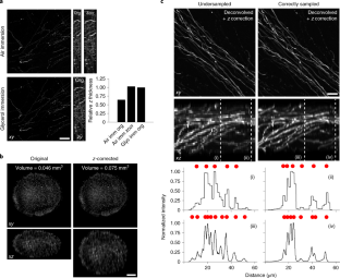
Spherical aberration (SA) occurs when light rays entering at different points of a spherical lens are not focused to the same point of the optical axis. SA that occurs inside the lens elements of a fluorescence microscope is well understood and corrected for. However, SA is also induced when light passes through an interface of refractive index (RI)-mismatched substances (i.e., a discrepancy between the RI of the immersion medium and the RI of the sample). SA due to RI mismatches has many deleterious effects on imaging. Perhaps most important for 3D imaging is that the distance the image plane moves in a sample is not equivalent to the distance traveled by an objective (or stage) during z-stack acquisition. This non-uniform translation along the z axis gives rise to artifactually elongated images (if the objective is immersed in a medium with a higher RI than that of the sample) or compressed images (if the objective is immersed in a medium with a lower RI than that of the sample) and alters the optimal axial sampling rate. In this tutorial, we describe why this distortion occurs, how it impacts quantitative measurements and axial resolution, and what can be done to avoid SA and thereby prevent distorted images. In addition, this tutorial aims to better inform researchers of how to correct RI mismatch–induced axial distortions and provides a practical ImageJ/Fiji-based tool to reduce the prevalence of volumetric measurement errors and lost axial resolution.
Peer review information Nature Protocols thanks Chrysanthe Preza and the other, anonymous, reviewer(s) for their contribution to the peer review of this work.
Kim, B. & Naemura, T. Blind depth-variant deconvolution of 3D data in wide-field fluorescence microscopy. Sci. Rep. 5, 9894 (2015).
Diel, E.E., Lichtman, J.W. & Richardson, D.S. Tutorial: avoiding and correcting sample-induced spherical aberration artifacts in 3D fluorescence microscopy. Nat Protoc 15, 2773–2784 (2020). https://doi.org/10.1038/s41596-020-0360-2
Schneider, C. A., Rasband, W. S. & Eliceiri, K. W. NIH Image to ImageJ: 25 years of image analysis. Nat. Methods 9, 671–675 (2012).
Ghosh, S. & Preza, C. Fluorescence microscopy point spread function model accounting for aberrations due to refractive index variability within a specimen. J. Biomed. Opt. 20, 75003 (2015).
Model, M. A., Fang, J., Yuvaraj, P., Chen, Y. & Zhang Newby, B. M. 3D deconvolution of spherically aberrated images using commercial software. J. Microsc. 241, 94–100 (2011).
Heine, J. et al. Three dimensional live-cell STED microscopy at increased depth using a water immersion objective. Rev. Sci. Instrum. 89, 053701 (2018).
Gibson, S. F. & Lanni, F. Experimental test of an analytical model of aberration in an oil-immersion objective lens used in three-dimensional light microscopy. J. Opt. Soc. Am. A 9, 154–166 (1992).
I have some questions regarding barrel distortion and pincushion distortion. Since they are related I have put them in single post.
Keller, H. E. Objectives for confocal microscopy. in Handbook of Biological Confocal Microscopy (ed Pawley, J. B.) (Springer, 1995).
Zhang, Q. et al. Quantitative refractive index distribution of single cell by combining phase-shifting interferometry and AFM imaging. Sci. Rep. 7, 2532 (2017).


 Ms.Cici
 8618319014500