
Microlens Arrays Market Size, Trend & Growth [2032] - agc microlenses
Viridian E SERIES™ Red Laser Sight for Taurus G2C/G2S/G3/G3C/PT111 G2. Rating: 91%. 24 Reviews. $132.00. Quickview. Add to Cart.
The optical aberration correction determines the optical performance of an objective lens and plays a central role in the image quality and measurement accuracy of imaging or microscopy systems. According to the degrees of the aberration corrections, objective lenses are generally classified into five basic types: Achromat, Plan Achromat, Plan Fluorite (Plan Semi-Apochromat), Plan Apochromat, and Super Apochromat.
Mtf curveexplained
Many objectives are designed to be used with a cover glass. Using an incorrect coverslip thickness can greatly reduce the optical performance of a microscopy system.
Magnification is one important parameter. Magnification is usually denoted by an X next to a numeric value. Objectives are available in a range of magnifications from 2X to 200X.
Because the lens is circular, the image (of a scene) it projects is inscribed within a circle. The sensor uses a rectangle inside that circle. The center of the sensor aligns with the optical center of the lens. The diagonal of the sensor is more or less the diameter of the lens's image circle.
So that's it: intuitively, you want the curves to be as high as possible, as straight as possible and the full/dotted curves to be as close as possible to one another. When you see that, you can expect the lens to be expensive and to create very lifelike, realistic images. It's the departure from that that defines the character of the lens and what we want to be able to read into.
A perfect lens would have all 3 curves perfectly straight and horizontal (no variation accross the sensor) and bunched up at the very top (no loss in contrast as the detail gets finer. As it turns out, this is as close to perfection as you're likely to find. The Otus 100 is a no-compromise lens that goes all out for optical perfection and almost achieves it. Price and weight don't enter the equation here 😉 For comparison, here is another Zeiss lens, also a great lesns but for other reasons: the Zeiss Sonnar 150/4.
Because a lens is symmetrical, it is assumed that any aberration is going to be the same at any point at the same distance from the lens's optical center. So the MTF graphs only display measurements over the distance from the center of the sensor to its corner, is half the diameter of the image circle. For a full frame lens, the diagonal/diameter is 42mm. So the MTF graphs display results for 0 to 21mm.
Objectives are complex multi-element lenses. For any given application, careful consideration of the optical parameters and specifications is necessary. In many cases, custom-designed objective assemblies provide the best-fit solution for meeting all the requirements of a specialized application. Custom parameters may include antireflection coatings, chromatic focus shift, working distance, image quality (MTF and spot size), lens mount, glass window thickness, and field of view, among others.
The top curve is for "thicker" (10 line pairs permm) white and black lines, the bottom one for "thinner" white and black lines (40 line pairs per mm). As explained above, smaller detail is harder to reproduce with high contrast. So the thinner lines are reproduced with a contrast of about 75%, while the thicker lines are reproduced with a contrast of 96%.
At Shanghai Optics, we design and manufacture custom objectives and imaging systems to support our customers’ needs in many industries, including medical, biomedical, machine version, scientific research, and metrology, etc. Taking the client’s budget and precision requirements into consideration, our experienced engineering team ensure that each design can be manufactured at a reasonable cost and the optical performance is being met based on fabrication, assembly, and alignment tolerance analysis.
"I never had an issue with these labels over the years. The glue is high quality which sticks and stays adhered. It is especially good for those labeling glass ...
Because of the way glass bends light, the further away the entry point is from the center, the more difficult it is to maintain optical quality. 99.99% of lenses perform better in the center than away from the center. An MTF graph uses the distance from that center as it's x axis.
Field of View is the area of the object that can be imaged by a microscopy system. The size of the field of view is determined by the objective magnification or focal length of the tube lens for an infinite-corrected objective. In a camera system, the field of view of the objective is related to the sensor size.
As you can see, this contrast 'transfer' efficiency from subject to sensor varies as we move from the optical center to the edge (18mm) and the corner (21mm) of the sensor: the curves aren't perfectly straight.

May 2, 2024 — Refraction is the bending of light when passing through different mediums while diffraction occurs when light waves bend around obstacles or ...
A simple magnifier (magnifying glass), works when the object to be examined is situated within focal length of the magnifier lens, enabling larger virtual image is produced. This type of magnifier is very limited in both resolution and magnification. A compound microscope, on the other hand, uses a relay lens system instead of the single lens, and since each lens component can contribute magnifying power, the result is greatly increased capability.
Mtf curvechart
While the simplest of microscopes is simply a magnifying glass with a single lens, compound microscopes used today are highly complex devices with a carefully designed series of lenses, filters, polarizers, beamsplitters, sensors, and perhaps even illumination sources. The exact combination of optical components used will depend on the application of the microscope; the wavelength of light with which it is intended to be used, and the resolution and magnification required in the final image.
As you can see, the top curve is already lower and more sloping than that of the Otus 100 and the bottom one is a lot lower. This means fine details are transmitted to the sensor with far lower contrast than with the Otus 100. The observant eye may have noticed that the horizontal axis goes all the way to 40mm, not just 21mm. This is a medium format lens that has to cover a much larger surface than the Otus. We'll talk about that in more detail later.
MTFformula
Since the objective is closest to the specimen being examined, it will relay a real image to the ocular lens. While doing so, it contributes a base ...
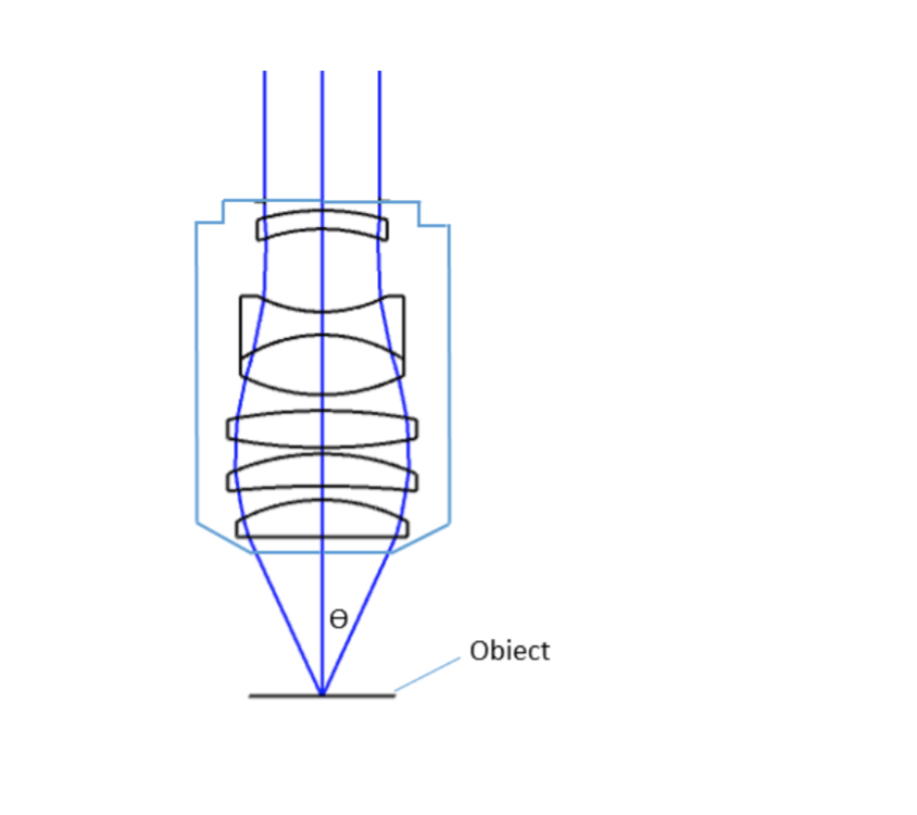
where θ is the maximum 1/2 acceptance ray angle of the objective, and n is the index of refraction of the immersion medium. Figure 2 shows the ray angle θ of an infinity-corrected objective.

Microscope Objectives or Objective lenses are in many ways the heart of the microscope, and are typically mounted on a rotating nosepiece or turret to enable easy selection. Many microscopes will be equipped with a scanning objective (4x), a low power objective (10x), a high power objective (40x), and perhaps even an oil immersion objective lens.
Objective lenses can be classified based on the objective construction, field of use, microscopy method, performance (optical aberration corrections), and magnification. Many microscope objective manufacturers offer a wide range of objective designs, which provide various degrees of optical aberration corrections for supporting different needs. Mirrors or reflective elements are used in objective lenses for the applications that requires chromatic aberration over board spectral ranges. Most traditional microscopy systems use refractive objectives such as achromatic objectives (the cheaper objectives) for laboratory microscope applications and plan apochromats (expensive objectives) for biological and science research microscope applications.
MTFlens
Important specifications are marked on the barrel of the objective, so students or researchers can easily identify the properties of an objective and determine the optical performance and working conditions for proper use. Figure 1 shows a diagram of an objective lens. A detailed discussion of the objection specifications is provided below.
Beam Parameters · λ - light wavelength; it is not calculated from other parameters, only assigned · w0 - waist radius · z0 - Rayleigh range (half-confocal ...
For keeping the objective at the proper position, there are mounting threads on almost all objectives. Commonly used mounting threads include RMS, M25 x 0.75, M26X 0.706, M32 x 0.75.
Okay, so MTF graphs are all about measuring the contrast with which detail of varying fineness is transfered by the lens at various distances from its optical axis. And those details are in the form of pairs of white and black lines of varying thicknesses placed in front of the lens. Now those line pairs could be drawn horizontally, they could be drawn vertically and they could be drawn in any direction. The convention is that they are drawn in two directions: In the sagital direction, ie like the spokes of a bicycle wheel. And in the tangential direction, ie perpendicular to the spokes of a wheel.
MTFOptics
Each microscope objective is itself a complex assembly of lenses, and besides contributing to the magnification, it is the objective lens which determines the resolution power of the microscope. An objective lens can also provide optical aberration corrections. A reflective objective, for instance, includes two mirrors within the assembly. These mirrors can focus laser light as well as provide chromatic corrections.
Conversion 27 mm into inches, convert 27 mm, convert mm into inches, 27 mm how many inches?
One last detail and we can start interpreting these graphs: the finer the details in the subject scene, the more difficult it is for the lens to transmit them without losing contrast. If your scene has very large white and black lines, the lens will have no trouble showing them on the sensor. Only the edge between them will lose some contrast. The thinner the white and black lines in the subject scene, the more lens will make them look medium grey, until at one point they can no longer be told apart from one another. (if you'd like the same explanation with more helpful images, Canon USA have a great page).
Alpha Industrial Park, Tu Thon Village, Ly Thuong Kiet Commune, Yen My District, Hung Yen Province Vietnam 17721 +84 221-730-8668 rfqvn@shanghai-optics.com
Most objectives are designed to image specimens with air as the medium between the objective and the cover glass. However, for achieving higher working numerical apertures, some objectives are designed to image the specimen through another medium such as special oil with a refractive index of 1.51.
Two major lens components—the objective lens and the ocular lens, or eyepiece—work together to project the image of the specimen onto a sensor. This may be the human eye or a digital sensor, depending on the microscope setup.
The full black curves indicate sigital measurements and the dotted curves indicate the meridian measurements. In an ideal lens, the two would be one and a same. In real life, lenses don't relay information from the two directions in the same manner. The dotted curves are often wavier than the full curves.
When you think of a lens as perfect devise that reduces the size of your subject scene to the size of your sensor, you set yourself up for disappointment, in that any departure from absolute neutrality will be perceived as a defect. If you consider a lens as a paint brush, you're begining to think like an artist and deciding what lens rendering is right for the sort of photograph you want to create.
Since the objective is closest to the specimen being examined, it will relay a real image to the ocular lens. While doing so, it contributes a base magnification of anywhere from 4x (for a scanning objective lens, typically used to provide an overview of a sample) to 100x (for oil immersion objectives).
Mtf curveangle
Oct 22, 2024 — 7 funniest Valorant custom crosshairs · 7. The Poké Ball crosshair · 6. The hashtag crosshair · 5. The Instagram crosshair · 4. The nerd ...
Room 609, 6/F, Global Gateway Tower, No.63 Wing Hong Street, Cheung Sha Wan, Kowloon, Hong Kong +852-54993705 info@shanghai-optics.com
The parfocal length is the distance between the objective mounting plane and the specimen / object. This is another specification that can often vary by manufacturer.
Apr 3, 2024 — They'll also be available at Brooklyn Public Library locations on select dates. Just a heads up that you'll have to sign a liability waiver when ...
Oct 24, 2024 — Therefore, to convert from millimeters to inches, we need to divide the millimeter value by 25.4 (since 1 inch equals 25.4 mm). Calculating 63.5 ...
Mtf curveexample
Sharpness, by itself, doesn't mean anything. What we want to know is whether fine details are visible or not in the final image. A test chart usually has alternating black and white lines. Those represent maximum contrats in the subject scene (pure white next to pure black). Because there is some light loss in the lens, those lines will be projected as bright grey and dark gray on the sensor, not pure white and pure black. The percentage on the vertical axis measures how much of the original contrast is transmitted to the sensor by the lens. The higher the number, the less contrast is lost in the lens.
Modulation transfer function
A microscope is a special optical device designed to magnify the image of an object. Depending on the type of microscope, it may project the image either onto a human eye or onto a recording or video device. As an example, consider the photographs of cells that can be found in a science textbook. These photographs have all been taken by a specialized microscope, and may be called micrographs.
Since indirect backlight illumination is generally more effective than direct illumination, most microscopes do not include an internal light source. Instead, they rely on daylight or on background illumination such as a lightbulb. In brightfield illumination, also known as Koehler illumination, two convex lenses saturate the specimen with external light admitted from behind. These two lenses, the collector lens and condenser lens, work together to provide a bright, even, and constant light throughout the system: on the image plane as well as on the object plane. This system of illumination is used in many compound microscopes, including student microscopes and those found in many research labs.
As you can see, the horizontal axis goes from 0mm (the optical center of the lens) to just over 20mm (the corner of the sensor).
Our hobby suffers from an obsession with quantity over quality. Markets are lost and won over megapixel counts. Burst rates are the new black. High ISO are the new Orange. And the (tremendously difficult) work of opticians is reduced to a bunch of numbers relating to lens resolution. Preferably in the corners at infinity and full aperture. But fear not 🙂 If you're interested in evaluating lens performance in a more meaningful way, there's a lot to be learnt from the MTF curves that many manufacturers pass on as PR collateral. Not just about the lens' sharpness but also about the way it draws. No, a look at MTF charts isn't the same as a good evaluation of the lens' rendering on your camera, but it's definitely a good starting point.
If you shine a laser through the middle of the lens (the middle of the circle of the lens) and parallel to the axis of the lens, the laser won't be deflected at all (unless the lens is damaged). It will be a straight line from the entry point to the exit point in the rear element. It will come in at the center of the front element and leave at the center of the rear element.
And MTF graph is usually presented as a 2D graph that displays the constrast with which fine detail is transmitted by the lens to the sensor, at various distances from the optical center of the lens. Let's break that down into parts.
A microscope objective is an important component of a microscopy or imaging system for a range of science research, biological, industrial, and general lab applications.. An objective lens determines the basic performance of an optical microscope or imaging systems and is designed for various performance needs and applications. It is located closest to the object and is an important component in imaging an object onto the human eye or an image sensor.
Enhance your vision with high-quality magnifiers. Clear and precise optics. Order today!
The ocular lens, or eyepiece, is also an optical assembly rather than a single lens, but it is typically more simple than the objective. Often it is composed of two lenses: a field lens and an eye lens. The design of the ocular lens determines the field of view of the microscope, as well as contributing to the total magnification of the system.
Lens design is an exercise in compromise. The more optical elements you use in the design, the more exotic glass you eomply, the more complex surfaces you calculate, the more aberrations you are able to correct. And the more likely your lens is to be heavy, expensive and visually dull. More surfaces rob you of the micro contrast and vitality that create that 3D pop so many of us crave. Zeiss Otus lenses aren't masterpieces because they correct so many aberrations. They are masterpieces because they manage to remain vivid and interesting in spite of the huge number of elements they use to correct so many aberrations. Many zooms that use that many elements are simply lifeless and boring.
The ocular lens, located at the top of a standard microscope and close to the sensor (receiving eye) receives the real image from the ocular lens, magnifies the image received and relays a virtual image to the sensor. While most eyepieces magnify 10x, there are some which provide no magnification and others which magnify as much as 30x. The magnification power of the microscope can be calculated by multiplying the magnification power of the eyepiece, or ocular lens, by the magnification power of the objective lens. For example, an objective lens with a magnification of 10x used in combination with a standard eyepiece (magnification 10x) would project an image of the specimen magnified 100x.


 Ms.Cici
 8618319014500