
Metal Detectors - Explore Scientific - detectors
This blog post aims to simplify the selection process by exploring popular lens mounts used in embedded vision and providing valuable insights to help you make an informed decision.
Ordinary lenses, working on the basis of refraction, have a focal length which is slightly wavelength-dependent due to the wavelength dependence of the refractive index (–> chromatic dispersion). This effect leads to chromatic aberrations of imaging systems and similar problems in other applications where an optical system is used for a wide range of optical wavelengths. Lens combinations (e.g., objectives for photographic cameras) can be designed such that chromatic aberrations are minimized. Most common is the use of achromatic doublets, i.e., lenses consisting of two different glass materials chosen such that the overall chromatic aberrations are largely canceled.
Unfortunately, the terms are also used differently by other authors. For example, it happens that a focal distance is assumed to be the same as a focal length. Therefore, some product catalogs specify focal lengths, which should actually be called focal distances, and in addition the effective focal length.
In contrast to focal lengths, focal distances are related not to the principal planes but rather to the vertex points of lenses (not caring about a housing, which may be further extended). The front focal distance is thus the distance between front focal point and the entrance surface of the optics, while the back focal distance is the distance between the back surface and the back focal point.
For instance, a lens with a focal length of 50 mm requires a larger holder height, rendering it irreconcilable with an M12 holder. M12-mount/CS-mount lenses typically have reduced focal lengths. A lens mount compatible with variable focal length lenses (zoom or varifocal lenses) could be selected for an embedded vision system that monitors production lines. This would allow the magnification to be adjusted to focus on specific aspects of the production process.
We have bunch of standard lenses ready to be coated on and reduce the lead time as well as end product cost. Check for our standard lenses here.
The angle of view of the camera is determined by the ratio of the image size on the film and the focal length. Film-based cameras have for a long time mostly used 35-mm film (also called 135 film according to ISO Standard 1007), where the image size on the film is typically 36 mm × 24 mm. (The width of the film spool is 35 mm, somewhat larger than 24 mm, as the picture does not extend to the edges of the spool.) A standard objective then has a focal length of 50 mm. However, modern digital cameras (particularly the more compact ones) often contain image sensors which are smaller than 36 mm × 24 mm, so that an objective lens with a correspondingly smaller focal length (e.g. 32 mm instead of 50 mm) is required for obtaining the same field of view. As many photographers are still used to the previously valid relation between focal length and angle of view, it has become common to specify the effective focal length of an objective of a digital camera as that focal length which would give the same angle of view in combination with ordinary 35-mm film. For example, an objective with a true focal length of 32 mm may then be said to have an effective focal length of 50 mm and thus function as a standard objective, rather than e.g. a macro or tele objective.
where it is assumed that the beam radius at the focus is much smaller than the initial beam radius <$w_0$>. (This condition is violated for beams with a too small incident radius; the focus is then larger than according to the given equation.) Also, it is assumed that the beam radius is significantly larger than the wavelength <$\lambda$>, so that the paraxial approximation is valid.
Edmund Optics offers the world’s largest inventory of off-the-shelf optical components, which includes an extensive selection of stock optical lenses such as achromatic lenses or aspheric lenses. Many of Edmund Optics’ lenses are offered with a variety of coating options for the ultraviolet (UV), visible, or infrared (IR) spectrum.
TFL (Through-Focal-Length) and TFL-II mounts are less common in embedded vision systems but have significant applications in scientific and research imaging. Due to the larger diameter of these mounts compared to the common C-mount, they are ideally suited for high-precision and resolution situations. Their primary applications include microscopy, scientific instruments, and particular industrial inspection arrangements.In contrast, the T-mount, known as the M42-mount, distinguishes itself from other mount-varieties. Sophisticated cameras predominantly employ it with large, high-resolution sensors. This mount type has a metric thread with a 42 mm diameter and 0.75 mm pitch (M42x0.75). This mount’s standard flange focal distance is 55 mm.The TFL-mount was designed for APS-C (27.9mm) sensors, which are too large for a C-mount but too small for an F-mount. The TFL-mount possesses thread dimensions of M35x0.75mm and shares the same flange distance of 17.526mm as the C-mount. The TFL-mount provides the same durability as the C-mount but accommodates larger sensors, bridging the limitations of the F-mount.
M42mount
Considerable confusion arises from the fact that in the context of photo cameras the term effective focal length is also used with an entirely different meaning, as explained in the following.
Similarly, one can define the back focal plane (or second focal plane) and back principal plane (or second principal plane), where horizontal rays occur on the left side, while on the right side one has converging rays for a focusing system and diverging rays for a defocusing system. If the refractive index is the same on the input and output side (e.g. ≈1 for air), the front focal length and back focal length are identical (apart from possible sign differences used by some authors) and can thus simply called the focal length. The two principal planes, however, generally do not coincide for thick lenses, and they can even lie outside a lens.
The dioptric power (also called focusing power) of a lens is defined as the inverse of the effective focal length (which is the same is the front and back focal length if the median on both sides of the optics is the same). This means that a strongly focusing lens has a small focal length, but a large dioptric power. For prescription glasses, it is common the specify the dioptric power, whereas the focal length is specified for standard lenses, microscope objectives, and photographic objectives.
OPTOMAN's AR-coated lenses are optimized for high laser power applications. These lenses can be used for intracavity, multi-kW CW, and ultrafast pulse applications. Sputtered anti-reflective coatings feature reflectance per surface down to R < 0.01%.
T-mount
Whether this rule can also be applied to an extended optical system with focal length <$f$> depends on the applied definition of <$f$>. It is useful to specify an effective focal length which is valid for such relations.
The sensor size and resolution determine the area a lens must cover and the level of captured detail. Modern embedded vision applications frequently employ high-resolution sensors to satisfy stringent image quality requirements. Ensuring that the lens mount chosen can accommodate the desired resolution is essential. While an S-mount lens (also called an M12 lens, with a thread diameter of 12mm) is suitable for most sensors used in embedded vision, large sensors designed to achieve higher resolution or pixel size will need a C-mount lens.At the same time, even the 1-inch (25.4 mm) diameter of the C-mount might not be enough in certain scenarios, which is when the F-mount becomes the optimal choice. In addition, the T-mount is superior to the C-mount for larger sensors and line scan cameras due to its substantially larger diameter. A larger sensor necessitates a lens that can cover the entire image area without compromising image quality.
Introducing TechNexion, the leading provider of cameras with C-mount and S-mount configurations. With our wide range of camera options, we cater to all your imaging needs.
Nikon developed the F-mount, primarily used for photography and videography. Although it is less common in embedded vision, the F-mount is the optimal choice when Nikon lens compatibility is essential. It is especially important in high-end imaging systems and configurations where alignment with professional camera lenses is essential.The F-mount is a bayonet-style mount system for Nikon SLR and DSLR cameras. This mount type has a 44mm diameter and a 46.5mm flange distance. The bayonet mechanism of the F-mount adds a layer of convenience, which manufacturers of large format cameras and line scan cameras appreciate greatly. F-mount is synonymous with Nikon’s SLR camera lens mount system, indicating its widespread adoption.Scientific imaging and machine vision applications emphasizing high-resolution and line scan cameras benefit from the F-mount’s versatility. It excels in situations requiring compatibility with large matrix sensors, where its expansive format shines. The F-mount has been in active production for over half a century, making it the only SLR lens mount to reach this remarkable benchmark.
The software products which are supporting our script language (e.g. RP Fiber Power and RP Coating) have now got a powerful debugger!
We offer precision optics lenses from 0.5 mm to 500 mm diameter. Surface quality can reach λ/10. All optical materials available.
The Model 02-014-1 is an air spaced, computer designed multi-element lens that is diffraction-limited when used with fibers having core diameters as large as 1200 microns. Operational wavelength is 1064 nm. The 02-014 reimages the emitting surface of the fiber with a 0.67× demagnification. Focused spot sizes are significantly smaller than those achievable with single-element lenses used in a similar collimating/focusing configuration. All optical elements are fabricated from high laser-damage resistant glasses and are anti-reflection coated to reduce reflectance per surface to 0.13%. The working distance between the lens and the target is sufficiently large to allow use of a gas nozzle to enhance the cutting or welding process and to prevent debris from depositing on the lens surface.
Enter input values with units, where appropriate. After you have modified some inputs, click the “calc” button to recalculate the output.
Avantier is proficient in producing customized lenses for all kinds of applications, ranging from prototyping to large-scale production.
Using our advertising package, you can display your logo, further below your product description, and these will been seen by many photonics professionals.
C mount1 32 un 2b
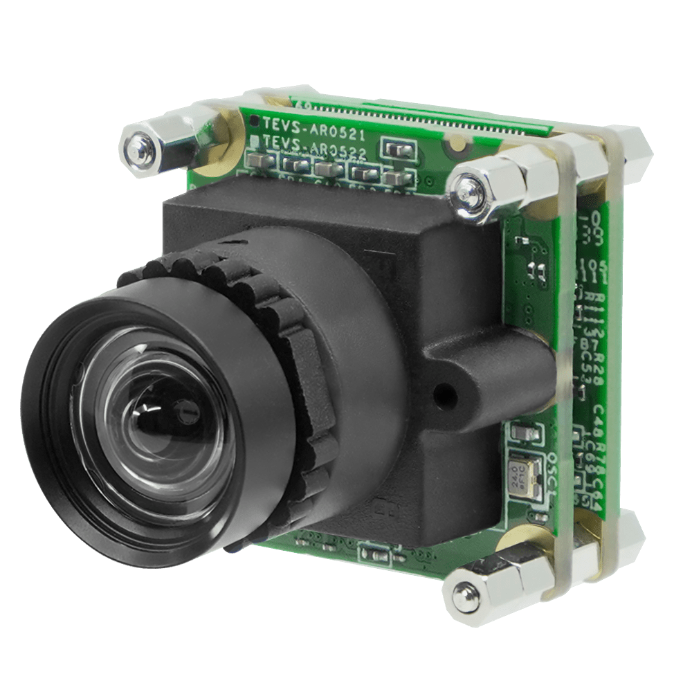
The S-mount, also called the M12 Mount, holds significant popularity within compact embedded vision devices such as handheld scanners and medical diagnostic devices. Its compact dimensions render it a preferred choice for scenarios where spatial constraints are considered.
A lens mount compatible with ultra-wide-angle lenses may be preferred in a robotics application that requires a wide-angle view. This would enable capturing a larger area without requiring extensive camera-to-subject distance.
For a focusing lens, this means a reduced phase delay for increasing <$r$> coordinate. Note that there are different sign conventions in wave optics, where a phase delay can correspond to a positive or negative change of a phasor (complex amplitude).
For a defocusing system, the front focal plane can be located on the output side; it contains a virtual focal point. Again, the focal length is the distance between principal plane and focal plane.
The focal distance should also not be confused with the working distance, which is the distance between a specimen and the lens housing. Note that a specimen is not necessarily placed in the focal plane, e.g. when the input light to an objective is not collimated.
For an optical system, which may consist of multiple lenses and other optical elements, the above definition of the focal length cannot be used, as it is not clear a priori for an extended system where to measure the distance to the focus: from the entrance into the optical system, from the exit, the middle, or some other position? In principle, an arbitrary definition of a reference point (e.g. the entrance or the middle) could be used, but that would in general mean that some common rules can not be applied, which e.g. hold for the radius of the beam waist at a focus behind some lens with a given focal length (see below), or the possible magnification of a telescope containing that optical system.
The C-mount connection comprises an imperial thread with a one-inch diameter and 32 threads per inch. This resembles a metric thread, with dimensions comparable to M25.5 x 0.75 mm.The rear focal distances of the C-mount and CS-mount connectors are an important differentiating characteristic. C-mount connectors have a fixed rear focal distance of 17.526 mm, exactly 5 mm more than CS-mount connectors. While a CS-mount lens cannot be used directly with a C-mount camera, a C-mount lens can be used with a CS-mount camera via a CS-mount adapter, typically a 5 mm spacer ring.
Our spherical lenses are widely used in a variety of industrial and detection cameras, microscopic objectives, spectral imaging, machine vision, infrared night vision and sensing, thermal imaging, environmental protection and biology. Lenses can be equipped with anti-reflective coatings, HR coatings and metallic mirror coatings, dielectric films and spectroscopic films.
The S-mount lens system employs a screw-threaded mounting approach and finds frequent utilization in board-level cameras. This mount type encompasses a 12mm metric thread diameter with a pitch of 0.5 mm (M12x0.5), with the “M” denoting metric dimensions measured in millimeters of the outer diameter.
Low-loss ion-beam-sputtered anti-reflection (AR) coatings with reflectivity less than 0.1% per surface and low-absorption high reflector mirror coatings are available on PPD lenses or can be applied to customer supplied substrates. PPD uses only IBS thin film deposition technology because it is a repeatable process which results in coatings that are durable, stable and easy to clean.
EKSMA Optics offers standard plano-convex, plano-concave, biconvex, biconcave, cylindrical lenses and lens kits made of BK7, UVFS or CaF2 optical materials. EKSMA Optics also has an extensive experience in manufacturing of custom optical lenses from a variety of other optical materials. Lenses of custom design can be produced in our CNC lens polishing facility and later coated for your application.
Enter input values with units, where appropriate. After you have modified some inputs, click the “calc” button to recalculate the output.
The explained definition delivers a focal length which can also be used in equations for the size of the focus (see below), for example.
Note that the locations of the left and right edges of the optical system (e.g. positions of outer lens surfaces, optical windows etc.) or its housing are not relevant for those definitions.
Note that the lens equation applies for rays, assuming that the paraxial approximation is valid, i.e., all angles relative to the beam axis remain small.
Artifex Engineering offers customised optical lenses such as achromatic or cylindrical lenses for almost any application in the UV to IR spectrum. Special requirements such as segmenting and black painted edges can be made on request. Visit our product page for more information. We look forward to your inquiry.
When it comes to embedded vision technology, choosing the suitable lens mount is crucial for capturing high-quality images and unlocking the full potential of your devices.
PPD manufactures custom, high precision optical components including spherical lenses, lens assemblies and spherical mirror substrates for imaging, machine vision and high energy laser applications from the ultraviolet (UV) through the near-infrared (NIR). Coated and uncoated optics are available from 2 mm to 8” in diameter and in a wide range of materials including fused silica, infrasil, N-BK7, YAG, SF11 and other high index glasses. If your radius of curvature is not yet determined, contact us for information on existing fabrication tooling and test plates, or send us your design specifications for a fully custom lens or mirror quotation.
Laserton offers various types of lenses, including plano-convex, plano-concave, double convex, double concave, meniscus, ball, achromatic and cylindrical lenses.
Note: this box searches only for keywords in the titles of articles, and for acronyms. For full-text searches on the whole website, use our search page.
The formula ignores the constant part of the optical phase change as well as optical aberrations. Note that depending on the function of the lens – for example, focusing collimated input beams or refocusing divergent light –, higher-order terms in the phase profile may be required to avoid optical aberrations.
The mount size is the diameter of the lens mount thread, and the flange distance is the distance between the lens mount surface and the image sensor. These parameters determine how compatible the lens is with the sensor. A larger mount size permits a larger lens, allowing more light to reach the sensor. Nonetheless, mount size is not the only factor influencing lens design; flange distance is also crucial.A shorter flange distance enables lenses to be positioned closer to the sensor, allowing for the development of shorter-focus lenses that are simpler and more cost-effective. In addition, a shorter flange distance enables the construction of more compact cameras than longer flange distances. The proper balance between mount size and flange distance is required for optimal optical image quality in embedded camera applications.If you’re developing a surveillance camera module with a small form factor, an M12 lens mount with a brief flange distance may be appropriate. In this scenario, its small size and simplicity of integration would be advantageous.
A lens with a given focal length <$f$> (taken as positive in the case of a focusing lens) creates a radially varying phase delay for a laser beam according to the following equation:
Knight Optical has an extensive lens portfolio which are suitable for a variety of applications. Our stock lenses included aspheric, achromatic doublet, ball & half ball, biconvex, cylindrical, condenser, Fresnel, planoconcave/convex, plastic and rod lenses. Knight Optical also offers custom lenses if our stock optics do not meet our customer’s requirements.
The lens’s field of view is the extent of the scene it can capture. It is affected by both the sensor’s capacity and the lens’s focal length. C-mounts are more prevalent than S-mounts in applications that need a large field of view.
The lens mount is a mechanical interface that securely attaches a camera lens to an imaging device, such as a sensor or camera module. This crucial component ensures proper alignment and positioning of the lens relative to the image sensor. Typically, the lens mount includes threaded screw holes, flanges, or other mechanisms that firmly attach the lens while maintaining precise alignment.When it comes to lens mounts, there are different styles available. However, the most commonly used mounting styles in embedded camera applications are the screw threaded and bayonet types. The screw-threaded type gets its name from threading your lens onto the camera body. It provides a secure connection between the lens and the camera, ensuring stability during use. On the other hand, the bayonet type uses three to four tabs to lock a lens tightly in place.
Enter input values with units, where appropriate. After you have modified some values, click a “calc” button to recalculate the field left of it.
Please do not enter personal data here. (See also our privacy declaration.) If you wish to receive personal feedback or consultancy from the author, please contact him, e.g. via e-mail.
Here you can submit questions and comments. As far as they get accepted by the author, they will appear above this paragraph together with the author’s answer. The author will decide on acceptance based on certain criteria. Essentially, the issue must be of sufficiently broad interest.
Ecoptik produces a wide range of spherical lenses of different types (including meniscus lenses, half ball lenses, custom hyper-hemisphere lenses and achromatic lenses). We are happy to produce custom lenses of many types.

If a collimated Gaussian beam with beam radius <$w_0$> hits a focusing lens with focal length <$f$>, the beam radius of the beam waist (focus) after the lens can be calculated with the equation
Csmount
The equation shows that what determines the minimum possible beam radius is not the focal length <$f$> alone, but rather the ratio of <$f$> to the radius of the open aperture of the lens, which sets a maximum to the input beam radius <$w_0$>. For a focusing or collimation lens, that ratio is essentially the numerical aperture of the lens.
Compactness is critical in applications with limited space, such as a handheld retina scanner for example. When compactness is a priority, placing the sensor near the camera housing is critical.Because of their reduced size and ubiquitous availability, developers prefer S-mount lens types over C/CS-mount lenses in most embedded vision applications. Consider the use of a body-worn camera by law enforcement officials. The lens mount should be small and lightweight to provide comfort and unobtrusiveness while capturing high-quality images.
Different sign conventions for focal lengths are used in the literature. For example, one may have a negative front focal length if the front focal point lies before the front principal plane. Obviously, any equations involving focal lengths should be used with the assumed sign conventions.
AMS Technologies offers a wide range of optical lenses manufactured from high-quality optical glass, but also crystals and other optical materials:
The C-mount is a well-established and widely adopted standard, particularly prominent in machine vision and industrial applications. C-mount lenses are widely utilized in robotics, automation, quality control, and surveillance systems due to their adaptability and seamless compatibility with a wide range of camera sensors.
Some lens mounts provide manual or motorized focus adjustments, which can benefit applications requiring precise focusing. Choosing a lens-to-mount combination that assures the highest focus quality is essential. For instance, a lens mount compatible with motorized focus control may be chosen in a medical imaging system. This allows healthcare providers to remotely adjust the camera’s focus without physically interacting with it.
One may eliminate chromatic aberrations altogether by using optical systems with mirrors only. A curved mirror with radius of curvature <$R$> has a focal length <$f = R / 2$> (for normal incidence), determined only by the geometry and thus independent of the wavelength. On the other hand, for non-normal incidence the focal length in the tangential direction is decreased by the cosine of the angle of incidence, and increased by the inverse cosine of that angle in the sagittal direction. Therefore, such mirrors can introduce astigmatism.
DPM Photonics offers precision lenses for collimating the output of high power fiber devices. We also sell focusing objective lenses.
Lens mount
The curvature radii are taken as positive values for convex surfaces and negative for concave surfaces. Positive results are obtained for focusing lenses, negative results for defocusing lenses. The last term is relevant only for thick lenses with substantial curvature on both sides. The formula delivers the focal length within the paraxial approximation, not considering spherical aberrations, for example.
A common (but not universally used) approach for the definition of focal lengths of extended systems is based on geometrical optics. For finding the front focal point, one calculates rays which are horizontal on the back side (see Figure 2), using the paraxial approximation. The optical system is considered as a “black box”, where one does not care about the actual ray paths; instead, one works with internal rays which are extrapolated from the outer rays. Based on those extrapolated rays, one can define the front principal plane (or first principal plane). The front focal length is then the distance between the front focal point (in the front focal plane) and the front principal plane (see Figure 2). Some authors define the focal length to be negative in the situation of Figure 2 because the focal point is located before the front principal plane; others take the absolute value.
By submitting the information, you give your consent to the potential publication of your inputs on our website according to our rules. (If you later retract your consent, we will delete those inputs.) As your inputs are first reviewed by the author, they may be published with some delay.
The focal length determines the lens’s magnification and the distance at which objects come into sharp focus. It affects the field of view and the capacity to photograph subjects up close or far away. The lens’s focal length determines the type of mount with which it is compatible.
Nikon Fmount
The following equation allows one to calculate the dioptric power and thus the focal length of lens made of a material with refractive index <$n$> and with curvature radii <$R_1$> and <$R_2$> on the two surfaces:
Curved laser mirrors usually have a curvature radius somewhere between 10 mm and 5 m. The fabrication of dielectric mirror coatings can be more difficult for very strongly curved mirror substrates, but with refined techniques it is possible to reach focal lengths of only a few millimeters, as required for some miniature lasers.
Now that you understand what camera lens mount types are, let us learn the factors you need to consider while picking the lens mount for your application. They are as follows:
where <$a$> is the distance from the original focus to the lens. This shows that <$b \approx f$> if <$a \gg f$>, but <$b > f$> otherwise. That relation can be intuitively understood: a focusing power <$1 / a$> would be required to collimate the incident beam (i.e. to remove its beam divergence), so that only a focusing power <$1 / f - 1 / a$> is left for focusing.
With our wide range of camera models and features, you can select the appropriate lens type that suits your needs perfectly. Check out our embedded vision solutions here.
Enter input values with units, where appropriate. After you have modified some values, click a “calc” button to recalculate the field left of it.
A mirror with a curvature radius <$R$> of the surface has a focal length <$f = R / 2$>, if the beam axis is normal to the mirror surface. (We take positive signs for concave curvatures and focusing mirrors.) If there is some non-zero angle <$\theta$> between the beam axis and the normal direction, the focal length is <$f_{\tan} = (R / 2) \cdot \cos \theta$> in the tangential direction (i.e., within the plane of incidence) and <$f_{sag} = (R / 2) / \cos \theta$> in the sagittal direction.
Note: the article keyword search field and some other of the site's functionality would require Javascript, which however is turned off in your browser.
For some applications, in particular for focusing of imaging systems, it is essential than the focal length of an optical system can be fine adjusted. The following physical principles can be used:
Curved mirrors are often used for focusing or defocusing light. For example, within laser resonators curved laser mirrors with dielectric coatings are more commonly used than lenses, mainly because they introduce lower losses.
The CS-mount is similar to the C-Mount, except it has a shorter flange focal distance, making it appropriate for smaller sensors. CS-mount lenses are commonly used in security cameras and machine vision installations because they allow for compact designs without sacrificing optical quality. This lens mount has a flange focal distance of 12.5 mm and is the ideal standard for low-cost embedded vision applications.The CS-mount’s specifications are nearly identical to the C-mount’s, except for a 5mm reduction in flange focal length. This makes CS-mount a viable solution for limited space, and the reduced focal distance allows for more streamlined designs without sacrificing optical quality.
If a divergent (rather than collimated) beam hits a focusing lens, the distance <$b$> from the lens to the focus becomes larger than <$f$> (Figure 2). The lens equation states that
Whether in industrial automation, robotics, machine vision, surveillance, medical imaging, or any other industry, TechNexion’s C-mount and S-mount cameras offer options to meet your specific imaging requirements.
Our C-mount cameras stand out with their standard C-mount lens interface. This widely used lens mount in the industry offers unmatched flexibility and compatibility with various lenses. On the other hand, our S-mount cameras are ideal for applications where space is limited or where a more streamlined and compact design is essential.
Various types of optical systems (e.g. microscope objectives and curved laser mirrors) can focus or defocus light, and the focal length is used for quantifying such effects. The simplest case is that of a thin focusing lens (Figure 1a). If a sufficiently large collimated beam of light is incident on the lens, the beam will be focused, and the focal length is the distance from the lens to that focus (assuming that the lens is surrounded by vacuum or air, not by some dense substance with a significant refractive index). For a defocusing lens (Figure 1b), the focal length is the distance from the lens to the virtual focus (indicated by the dashed lines), taken as a negative value. Some authors use different sign conventions, however, in particularly concerning the front and back focal length (see below).


 Ms.Cici
 8618319014500