
Magnifying Glasses for Low Vision and Other Uses - uses for magnifying glass
U.2 was formerly known as SFF-8639 is a 2.5" SSD form factor, whilst the U.3 is an evolution of the U.2 form factor. These are designed specifically for enterprise and data centre environments. U.3 are backwards compatible with U.2.
A smaller version of the full-size SATA SSD, this SSDs can still be found in laptops and industrial applications - much like digital signage and PoS devices. Low on power consumption and a small form factor, it has a max bandwidth of 6 gigabits per second (Gbps). Comparing to M.2 SSDs, mSATA uses just SATA, whereas M.2 uses SATA and PCIe NVMe - as well as differences in speed, performance and sizes - all which weigh in M.2's favour.
F*tan(theta) calculations are used in camera calibration processes, where distortion parameters are estimated for correcting captured images. Lens designers often utilize F*tan(theta) calculations during the design phase to predict and minimize distortion in the final lens. This helps create lenses with minimal image curvature and ensures accurate image reproduction.
TV Distortion, as the name suggests, originated in the context of television applications. It can be calculated using the following formula:
Drew is Marketing Lead at Simms, leading our marketing department. Drew has a strong knowledge datacentre and server proposition, and leads on our industrial and embedded side of the business also.
We also provide various customization services, including camera enclosures, resolution, frame rate, and sensors of your choice, to ensure our cameras fit perfectly into your embedded vision applications.
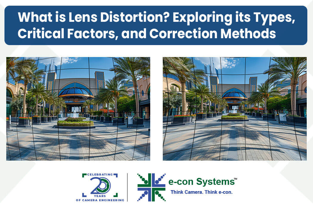
In this blog, we break down distortion parameters in lens datasheets and the three ways in which distortion is represented.
Mathematically, distortion can be represented in three different ways in the lens datasheet; let us look at each of them in detail.
F-Tan (Theta) method uses the tan(theta) relationship to calculate a reference height based on magnification, and the F(Theta) method uses F*theta (radians) to represent the ideal image point location based on its angular position.
Such form factors determine the shape and sizes that SSDs come in - much like the chassis of a car determining the compatibility with different roads. Like never before, understanding such form factors is key, not only deciding on the device such an SSD can fit into, but all nurturing the performance capabilities and potential applications.
F(Theta) method focuses on the angular relationship between the ideal undistorted image point and the actual distorted image point without needing magnification information.
Diagonal Field of View (FOV) at a Specific Image Distance: Values provided at different image distances (e.g., 124° @ 10mm)
The 2.5" (inch) SSD is widely found and compatible with most laptops and desktops. Resembling HDDs, many users will look to this SSD when replacing a HDD, allowing for compatibility when upgrading. Using SATA technology and protocol, this traditional in nature as things stand right now SSD form factor is typically mounted into the SSD tray within a PC.
Optical distortion represents the overall distortion parameter of the optical system. F-Tan theta or optical distortion can be calculated using the following formula.
Part of the EDSFF family like the E1.S and E1.L, the E3.S has a growing use case for mainstream NVMe server storage subsystems. The E3.L is as above but mainly for systems and platforms that need max capacity for each “U” config that needs a deeper chassis.
Solid State Drives (SSDs) have broken through as indispensable components, transforming storage and the systems they occupy. Speed, reliability, and efficiency have been revolutionised - but outside of this, the physical make up of their integration into modern computing systems have also seen physical change - all in the form of different SSD form factors.
F-Theta lenses are specifically designed to maintain a constant image size (or spot size for lasers) across a scan field. The F-Theta calculation helps ensure the accuracy of this constant size by measuring deviations from the ideal. These lenses are used in various applications like laser marking and engraving, laser cutting, 3D printing and LiDAR.
Both methods can be used to estimate distortion, but they can be more applicable in certain situations. F-Tan (Theta) is preferred when the focus is on object size and magnification changes due to distortion. And the F(Theta) method is used to get the angular relationship of distorted image points without needing magnification information.
Lens datasheets often include distortion information to help photographers and engineers understand how the lens behaves. Lens distortion refers to the phenomenon where straight lines in a scene appear curved in the final image. This happens because lenses don’t perfectly focus light from all parts of the field of view.
Using NVMe as a technology with the PCIe protocol, has much higher data transfer speed advantages over 2.5" and also as a form factor, is much smaller - meaning it is far more appropriate for data centre and cloud servers, as well as use in IoT devices and embedded solutions. Due to its size and ability to be longer, thus slim and small form factor works in laptops and notebooks well.
The F-Tan (Theta) method uses the tangent function to relate the angle to object size and magnification. Whereas the F(Theta) method focuses on the angular position of the image point relative to the centre. Both the methods require the focal length (F) and the diagonal FOV (degrees). But in the F(Theta) method the FOV in degrees is converted to radians.
Part of the EDSFF family and rising to prominence in the market, E1.S and E1.L are bringing consolidation and flexibility to the market for data centres. What's more, they're playing a much heavier role in industrial use, specifically in edge devices and ADAS. E1.S and “S” stand for short is built just a bit longer than M.2, but wider for more NAND flash capacity. E1.L and “L” for long is often described as a rule form factor for denser storage environments.
Imagine a scene with a square grid. In barrel distortion, the grid would bulge outwards, making the squares appear wider on the edges. Meanwhile, in pincushion distortion, the grid would sink inwards, making the squares appear narrower on the edges. Mustache distortion would cause the grid lines to become wavy.
The formula calculates the difference between the expected height of an object based on the sensor size and its actual distorted height based on the distortion values and field of view. This difference is then expressed as a percentage of the vertical sensor size to provide a measure of barrel distortion.
A negative value indicates barrel distortion (objects appear smaller towards the edges). In the above example, the calculation shows a higher barrel distortion (-39.5%) at a larger image distance (10mm). As the image distance decreases (9mm and 5mm), the distortion percentages become less negative, indicating a decrease in the barrel effect.


Prabu is the Chief Technology Officer and Head of Camera Products at e-con Systems, and comes with a rich experience of more than 15 years in the embedded vision space. He brings to the table a deep knowledge in USB cameras, embedded vision cameras, vision algorithms and FPGAs. He has built 50+ camera solutions spanning various domains such as medical, industrial, agriculture, retail, biometrics, and more. He also comes with expertise in device driver development and BSP development. Currently, Prabu’s focus is to build smart camera solutions that power new age AI based applications.
The F*tan(theta) method is a more general approach to calculating distortion. It’s often used for initial distortion assessment in various lenses, including photographic lenses. This method helps understand how straight lines deviate from their ideal positions due to distortion.


 Ms.Cici
 8618319014500