
Light sheet microscopy - light sheet
Zhu, R., Chen, L. & Zhang, H. Computer holography using deep neural network with Fourier basis. Opt. Lett. 48, 2333–2336 (2023).
Many approaches have been proposed to accelerate the CGH generation and improve its quality5,6,7,8,9. High-quality CGH generation is a time-consuming process, and advances in this area have been achieved by integrating deep learning techniques10,11,12. Conventional neural networks (CNN), such as U-Net, are ideal for CGH prediction due to their high-resolution and high-speed capabilities13. Nonetheless, real-time 4K holographic displays remains a significant challenge for learning-based CGH algorithms due to the high computational burden.
If the CGH is generated for a 2D reconstruction, \({D}_{d}\) is directly input into the encoding CNN. Note that using a CNN to generate 2D scenes for different depth layers has been proposed by Ryu et al.30, but their method is not optimized for layered CGH generation because the CNN need to be used multiple times for each layer. In our method, the CNN is used once for multiples layers. For layered 3D scenes, the complex amplitude in the CGH plane from different each layer is added before encoding. For example, if the 3D scene is composed of 2 layers \({d_1}\) and \({d_2}\), the complex amplitude in the CGH plane is calculated by adding the complex amplitude \({D}_{d1}\) and \({D}_{d2}\) propagated from each layer:
A light wave is an electromagnetic wave that travels through the vacuum of outer space. Light waves are produced by vibrating electric charges. The nature of such electromagnetic waves is beyond the scope of The Physics Classroom Tutorial. For our purposes, it is sufficient to merely say that an electromagnetic wave is a transverse wave that has both an electric and a magnetic component.
Xiao, J., Zhang, W. & Zhang, H. Sampling analysis for Fresnel diffraction fields based on phase space representation. JOSA A 39, A15–A28 (2022).
Ryu, W. J., Lee, J. S. & Won, Y. H. Continuous depth control of phase-only hologram with depth embedding block. IEEE Photon. J. 14, 1–7 (2022).
Our model of the polarization of light provides some substantial support for the wavelike nature of light. It would be extremely difficult to explain polarization phenomenon using a particle view of light. Polarization would only occur with a transverse wave. For this reason, polarization is one more reason why scientists believe that light exhibits wavelike behavior.
In Fig. 7, we show the numerical and optical reconstructions obtained using different methods. The images are from DIV2K dataset. The generation speed for a 2D reconstruction is 18.03 ms, 54.82 ms and 18.03 ms, respectively. The proposed phase (w/learned phase) and zero phase (w/o phase) are not image-dependent, and they are applied to any target image. The CNN predicted phase is image-dependent, and it is generated according to the input image through a CNN. In the reconstruction, the CNN predicted phase produces better results than the zero-phase method. But the generation time is much longer because a CNN is used to process the target image. Although real-time reconstruction can be achieved in the case of 2D reconstruction, where only a 2D image is processed by a CNN. It would be inefficient in the case of layered scene where multiple images are input into the CNN separately. In contrast, our proposed method achieves a comparable quality while maintaining a fast generation time.
Polarizingtopic meaning
The transverse nature of an electromagnetic wave is quite different from any other type of wave that has been discussed in The Physics Classroom Tutorial. Let's suppose that we use the customary slinky to model the behavior of an electromagnetic wave. As an electromagnetic wave traveled towards you, then you would observe the vibrations of the slinky occurring in more than one plane of vibration. This is quite different than what you might notice if you were to look along a slinky and observe a slinky wave traveling towards you. Indeed, the coils of the slinky would be vibrating back and forth as the slinky approached; yet these vibrations would occur in a single plane of space. That is, the coils of the slinky might vibrate up and down or left and right. Yet regardless of their direction of vibration, they would be moving along the same linear direction as you sighted along the slinky. If a slinky wave were an electromagnetic wave, then the vibrations of the slinky would occur in multiple planes. Unlike a usual slinky wave, the electric and magnetic vibrations of an electromagnetic wave occur in numerous planes. A light wave that is vibrating in more than one plane is referred to as unpolarized light. Light emitted by the sun, by a lamp in the classroom, or by a candle flame is unpolarized light. Such light waves are created by electric charges that vibrate in a variety of directions, thus creating an electromagnetic wave that vibrates in a variety of directions. This concept of unpolarized light is rather difficult to visualize. In general, it is helpful to picture unpolarized light as a wave that has an average of half its vibrations in a horizontal plane and half of its vibrations in a vertical plane.
In addition to generating CGHs for 2D reconstructions, we demonstrate the ability of our method to reconstruct layered 3D scenes in Fig. 3.
The structure of our method is illustrated in Fig. 1. Our model is designed to generate CGH for 2D reconstructions at different depths and layered 3D scenes. Here, 6 target depth layers are set ranging from 160 to 210 mm with an interval of 10 mm. For each depth layer, an initial zero phase is used as learnable parameters during the training process. As shown in Fig. 1a, for each input amplitude, its depth layer is selected randomly from the 6 target depth layers. The input amplitude is then given the corresponding initial phase. After diffraction from the image plane to the CGH plane with the Angular Spectrum Method (ASM), a CNN is utilized to encode the CGH. The amplitude of numerical reconstruction is then compared with the input amplitude for self-supervision. Further details of the training process are introduced in Methods section.
A Polaroid filter is able to polarize light because of the chemical composition of the filter material. The filter can be thought of as having long-chain molecules that are aligned within the filter in the same direction. During the fabrication of the filter, the long-chain molecules are stretched across the filter so that each molecule is (as much as possible) aligned in say the vertical direction. As unpolarized light strikes the filter, the portion of the waves vibrating in the vertical direction are absorbed by the filter. The general rule is that the electromagnetic vibrations that are in a direction parallel to the alignment of the molecules are absorbed.
Converter card for converting infra-red light into visible light. Held directly in a laser to act as a sensor.
Wu, J., Liu, K., Sui, X. & Cao, L. High-speed computer-generated holography using an autoencoder-based deep neural network. Opt. Lett. 46, 2908–2911 (2021).
It is possible to transform unpolarized light into polarized light. Polarized light waves are light waves in which the vibrations occur in a single plane. The process of transforming unpolarized light into polarized light is known as polarization. There are a variety of methods of polarizing light. The four methods discussed on this page are:
Polarization has a wealth of other applications besides their use in glare-reducing sunglasses. In industry, Polaroid filters are used to perform stress analysis tests on transparent plastics. As light passes through a plastic, each color of visible light is polarized with its own orientation. If such a plastic is placed between two polarizing plates, a colorful pattern is revealed. As the top plate is turned, the color pattern changes as new colors become blocked and the formerly blocked colors are transmitted. A common Physics demonstration involves placing a plastic protractor between two Polaroid plates and placing them on top of an overhead projector. It is known that structural stress in plastic is signified at locations where there is a large concentration of colored bands. This location of stress is usually the location where structural failure will most likely occur. Perhaps you wish that a more careful stress analysis were performed on the plastic case of the CD that you recently purchased.
Shi, L., Li, B. & Matusik, W. End-to-end learning of 3d phase-only holograms for holographic display. Light Sci. Appl. 11, 247 (2022).
Our method is optimized with the ideal ASM, which may not accurately simulate the wave propagation in actual displays. Recent advances in learned diffraction models, such as Neural 3D Holography and Time-multiplexed Neural Holography, can be used for accurate wave propagation and as a loss function16,17.
Chakravarthula, P., Peng, Y., Kollin, J., Fuchs, H. & Heide, F. Wirtinger holography for near-eye displays. ACM Trans. Graph. (TOG) 38, 1–13 (2019).
Polarizingperson meaning
Jang, S.-W. et al. Complex spatial light modulation capability of a dual layer in-plane switching liquid crystal panel. Sci. Rep. 12, 1–14 (2022).
Unpolarized light can also undergo polarization by reflection off of nonmetallic surfaces. The extent to which polarization occurs is dependent upon the angle at which the light approaches the surface and upon the material that the surface is made of. Metallic surfaces reflect light with a variety of vibrational directions; such reflected light is unpolarized. However, nonmetallic surfaces such as asphalt roadways, snowfields and water reflect light such that there is a large concentration of vibrations in a plane parallel to the reflecting surface. A person viewing objects by means of light reflected off of nonmetallic surfaces will often perceive a glare if the extent of polarization is large. Fishermen are familiar with this glare since it prevents them from seeing fish that lie below the water. Light reflected off a lake is partially polarized in a direction parallel to the water's surface. Fishermen know that the use of glare-reducing sunglasses with the proper polarization axis allows for the blocking of this partially polarized light. By blocking the plane-polarized light, the glare is reduced and the fisherman can more easily see fish located under the water.
Shi, L., Li, B., Kim, C., Kellnhofer, P. & Matusik, W. Towards real-time photorealistic 3D holography with deep neural networks. Nature 591, 234–239 (2021).
Cem, A., Hedili, M. K., Ulusoy, E. & Urey, H. Foveated near-eye display using computational holography. Sci. Rep. 10, 14905 (2020).
Polarization can also occur by the refraction of light. Refraction occurs when a beam of light passes from one material into another material. At the surface of the two materials, the path of the beam changes its direction. The refracted beam acquires some degree of polarization. Most often, the polarization occurs in a plane perpendicular to the surface. The polarization of refracted light is often demonstrated in a Physics class using a unique crystal that serves as a double-refracting crystal. Iceland Spar, a rather rare form of the mineral calcite, refracts incident light into two different paths. The light is split into two beams upon entering the crystal. Subsequently, if an object is viewed by looking through an Iceland Spar crystal, two images will be seen. The two images are the result of the double refraction of light. Both refracted light beams are polarized - one in a direction parallel to the surface and the other in a direction perpendicular to the surface. Since these two refracted rays are polarized with a perpendicular orientation, a polarizing filter can be used to completely block one of the images. If the polarization axis of the filter is aligned perpendicular to the plane of polarized light, the light is completely blocked by the filter; meanwhile the second image is as bright as can be. And if the filter is then turned 90-degrees in either direction, the second image reappears and the first image disappears. Now that's pretty neat observation that could never be observed if light did not exhibit any wavelike behavior.
The architecture of the encoding CNN is shown in Fig. 10. Here, we use the same Down-sampling and Up-sampling block as our previous CCNN-CGH network21. The encoding CNN uses only one complex-valued convolution (C-Conv) layer, ReLU (C-ReLU) layer and deconvolution (C-Deconv) layer. The input is the complex amplitude after ASM from the image plane. The convolution kernel size of C-Conv is 3 × 3, and the stride is 2. The channel number is 18 after the C-Conv. The convolution kernel size of C-Deconv is 4 × 4, and the stride is 2. The output is a complex amplitude and its phase is used as the phase-only CGH.
Chakravarthula, P., Tseng, E., Srivastava, T., Fuchs, H. & Heide, F. Learned hardware-in-the-loop phase retrieval for holographic near-eye displays. ACM Trans. Graph. (TOG) 39, 1–18 (2020).
Polarizingmeaning in Chemistry
Learning-based computer-generated hologram (CGH) demonstrates great potential for real-time high-quality holographic displays. However, real-time 4K CGH generation for 3D scenes remains a challenge due to the computational burden. Here, a variant conventional neural network (CNN) is presented for CGH encoding with learned layered initial phases for layered CGH generation. Specifically, the CNN predicts the CGH based on the input complex amplitude on the CGH plane, and the learned initial phases act as a universal phase for any target images at the target depth layer. These phases are generated during the training process of the coding CNN to further optimize the quality. The CNN is trained to learn encoding 3D CGH by randomly selecting the depth layer in the training process, and contains only 938 parameters. The generation time for a 2D 4K CGH is 18 ms, and is increased by 12 ms for each layer in a layered 3D scene. The average Peak Signal to Noise Ratio (PSNR) of each layer is above 30dB in the depth range from 160 to 210 mm. Experiments verify that our method can achieve real-time layered 4K CGH generation.
Open Access This article is licensed under a Creative Commons Attribution 4.0 International License, which permits use, sharing, adaptation, distribution and reproduction in any medium or format, as long as you give appropriate credit to the original author(s) and the source, provide a link to the Creative Commons licence, and indicate if changes were made. The images or other third party material in this article are included in the article’s Creative Commons licence, unless indicated otherwise in a credit line to the material. If material is not included in the article’s Creative Commons licence and your intended use is not permitted by statutory regulation or exceeds the permitted use, you will need to obtain permission directly from the copyright holder. To view a copy of this licence, visit http://creativecommons.org/licenses/by/4.0/.
To generate 3D layered scene, each layer is combined with the predicted phase at the corresponding depth. After ASM to the CGH plane, the CNN is used to encode the synthetized complex amplitude. The detailed process is introduced in Methods section. The images are from DIV2K dataset and pixabay. The first 3D scene contains two objects placed at 160 mm and 190 mm, respectively. In Fig. 3a, the letter is in focus, while in Fig. 3c, the castle is in focus. The second 3D scene contains two objects placed at 180 mm and 210 mm, respectively. In Fig. 3b, the rectangle is in focus, while in Fig. 3d, the cat is in focus, demonstrating that our model can generate layered 3D scenes.
Polarising orpolarizing
Park, S., Lee, J., Choi, W., Park, S.-W. & Kim, H. Smoothing of inter-layer edge artifacts in depth-map computer-generated holograms. Opt. Lett. 47, 6421–6424 (2022).
Here, we show detailed experiments on the learned phase. Using CNN for CGH encoding has been widely used in previous researches11,19,22. Our encoding CNN plays a similar role to encode the complex amplitude into CGH. The encoding CNN used is similar to our previous CCNN model21. The main difference is that we proposed a non-image-dependent initial phase for each depth layer. Thus, we firstly show a comparison of using and not using the proposed phase.
Zhong, C. et al. Real-time high-quality computer-generated hologram using complex-valued convolutional neural network. IEEE Trans. Vis. Comput. Graph. (2023).
Zhong, C., Sang, X., Yan, B. et al. Real-time 4K computer-generated hologram based on encoding conventional neural network with learned layered phase. Sci Rep 13, 19372 (2023). https://doi.org/10.1038/s41598-023-46575-1
It should be noted that HoloNet and our previous CCNN-CGH model used a CNN to predict an image-dependent initial phase. However, it is inefficient for a layered 3D scene if each layer is input into the CNN separately. To accelerate the generation, a non-image-dependent initial phase is presented to avoid using CNN to process the input image. To further compare the proposed method, zero phase, CNN predicted phase, we show the numerical and optical experiment in Fig. 7. The encoding CNN is the same, and the CNN used to predict initial phase is the same from our CCNN-CGH.
In order to optimize the layered 3D reconstruction, Self-holo is proposed to use a CNN to predict the WRP with RGBD input similar to Tensor Holography, and another CNN to encode the CGH22. The 3D scene is divided into 3 layers for layered self-supervision. The depth range of reconstruction is also related to receptive field of the CNN for WRP prediction. In summary, using a CNN to process the input image for WRP prediction may result in constraints on the depth of field and receptive field, and generating multiple 2D CGHs can be computationally burdensome. To improve the quality, previous research has also explored various strategies involving training strategy, dataset, and loss function23,24,25. However, these approaches primarily focus on optimizing the training process and related aspects, rather than optimizing the neural network architecture. In contrast, our method takes a novel approach by optimizing the neural network architecture. We achieve this optimization by introducing a learned initial phase instead of relying on a CNN-predicted initial phase11. Our method can be combined with existing strategies to further enhance performance.
Polarization also occurs when light is scattered while traveling through a medium. When light strikes the atoms of a material, it will often set the electrons of those atoms into vibration. The vibrating electrons then produce their own electromagnetic wave that is radiated outward in all directions. This newly generated wave strikes neighboring atoms, forcing their electrons into vibrations at the same original frequency. These vibrating electrons produce another electromagnetic wave that is once more radiated outward in all directions. This absorption and reemission of light waves causes the light to be scattered about the medium. (This process of scattering contributes to the blueness of our skies, a topic to be discussed later.) This scattered light is partially polarized. Polarization by scattering is observed as light passes through our atmosphere. The scattered light often produces a glare in the skies. Photographers know that this partial polarization of scattered light leads to photographs characterized by a washed-out sky. The problem can easily be corrected by the use of a Polaroid filter. As the filter is rotated, the partially polarized light is blocked and the glare is reduced. The photographic secret of capturing a vivid blue sky as the backdrop of a beautiful foreground lies in the physics of polarization and Polaroid filters.
Georgieva, A., Belashov, A. V. & Petrov, N. V. Optimization of DMD-based independent amplitude and phase modulation by analysis of target complex wavefront. Sci. Rep. 12, 7754 (2022).
The first filter will polarize the light, blocking one-half of its vibrations. The second filter will have no affect on the light. Being aligned parallel to the first filter, the second filter will let the same light waves through.
Average PSNR and SSIM of each depth layers using proposed method with learned phase (w/phase) and traditional method with zero phase (w/o phase).
Chang, C., Bang, K., Wetzstein, G., Lee, B. & Gao, L. Toward the next-generation VR/AR optics: A review of holographic near-eye displays from a human-centric perspective. Optica 7, 1563–1578 (2020).
where S is the size of the convolution kernel, \({C}_{in}\) is the input channel number, 1 is the bias of the kernel. \({C}_{out}\) is the output channel number. In C-Conv, the parameters are doubled. Thus, the parameter number for our encoding CNN is 938. Compared with millions of parameters in previous methods. The number of parameters is very small in our CNN.
Polarization is also used in the entertainment industry to produce and show 3-D movies. Three-dimensional movies are actually two movies being shown at the same time through two projectors. The two movies are filmed from two slightly different camera locations. Each individual movie is then projected from different sides of the audience onto a metal screen. The movies are projected through a polarizing filter. The polarizing filter used for the projector on the left may have its polarization axis aligned horizontally while the polarizing filter used for the projector on the right would have its polarization axis aligned vertically. Consequently, there are two slightly different movies being projected onto a screen. Each movie is cast by light that is polarized with an orientation perpendicular to the other movie. The audience then wears glasses that have two Polaroid filters. Each filter has a different polarization axis - one is horizontal and the other is vertical. The result of this arrangement of projectors and filters is that the left eye sees the movie that is projected from the right projector while the right eye sees the movie that is projected from the left projector. This gives the viewer a perception of depth.
The most common method of polarization involves the use of a Polaroid filter. Polaroid filters are made of a special material that is capable of blocking one of the two planes of vibration of an electromagnetic wave. (Remember, the notion of two planes or directions of vibration is merely a simplification that helps us to visualize the wavelike nature of the electromagnetic wave.) In this sense, a Polaroid serves as a device that filters out one-half of the vibrations upon transmission of the light through the filter. When unpolarized light is transmitted through a Polaroid filter, it emerges with one-half the intensity and with vibrations in a single plane; it emerges as polarized light.
with overhang, c) continuous beam, d) a cantilever beam, e) a beam fixed (or restrained) ... averaged across the thickness, t, and hence it is ... beam in three- ...
Then ASM is used to calculate the diffraction from the image plane to the SLM plane. The complex amplitude \({D}_{d}\) in the SLM plane is calculated by:
Lens calculator - Calculating the focal length. The focal length f´ virtually serves to calculate the required lens and is thus the most important ...
3. Consider the three pairs of sunglasses below. Identify the pair of glasses is capable of eliminating the glare resulting from sunlight reflecting off the calm waters of a lake? _________ Explain. (The polarization axes are shown by the straight lines.)
Liu, K., Wu, J., He, Z. & Cao, L. 4K-DMDNet: Diffraction model-driven network for 4k computer-generated holography. Opto-Electron. Adv. 220135–1 (2023).
Chen, C. et al. Multi-depth hologram generation using stochastic gradient descent algorithm with complex loss function. Opt. Express 29, 15089–15103 (2021).
Peng, Y., Choi, S., Padmanaban, N. & Wetzstein, G. Neural holography with camera-in-the-loop training. ACM Trans. Graph. (TOG) 39, 1–14 (2020).
Chen, L., Zhu, R. & Zhang, H. Speckle-free compact holographic near-eye display using camera-in-the-loop optimization with phase constraint. Opt. Express 30, 46649–46665 (2022).
The alignment of these molecules gives the filter a polarization axis. This polarization axis extends across the length of the filter and only allows vibrations of the electromagnetic wave that are parallel to the axis to pass through. Any vibrations that are perpendicular to the polarization axis are blocked by the filter. Thus, a Polaroid filter with its long-chain molecules aligned horizontally will have a polarization axis aligned vertically. Such a filter will block all horizontal vibrations and allow the vertical vibrations to be transmitted (see diagram above). On the other hand, a Polaroid filter with its long-chain molecules aligned vertically will have a polarization axis aligned horizontally; this filter will block all vertical vibrations and allow the horizontal vibrations to be transmitted.
In the same manner, two Polaroid filters oriented with their polarization axes perpendicular to each other will block all the light. Now that's a pretty cool observation that could never be explained by a particle view of light.
Third Order Fresnel Lens · The Fresnel (pronounced Fra-NELL, or Fray-NELL) Lens was invented by Augustin-Jean Fresnel in 1822. · Presque Isleʼs Third Order ...
Polarization of light by use of a Polaroid filter is often demonstrated in a Physics class through a variety of demonstrations. Filters are used to look through and view objects. The filter does not distort the shape or dimensions of the object; it merely serves to produce a dimmer image of the object since one-half of the light is blocked as it passed through the filter. A pair of filters is often placed back to back in order to view objects looking through two filters. By slowly rotating the second filter, an orientation can be found in which all the light from an object is blocked and the object can no longer be seen when viewed through two filters. What happened? In this demonstration, the light was polarized upon passage through the first filter; perhaps only vertical vibrations were able to pass through. These vertical vibrations were then blocked by the second filter since its polarization filter is aligned in a horizontal direction. While you are unable to see the axes on the filter, you will know when the axes are aligned perpendicular to each other because with this orientation, all light is blocked. So by use of two filters, one can completely block all of the light that is incident upon the set; this will only occur if the polarization axes are rotated such that they are perpendicular to each other.
In summary, a novel approach for generating 3D CGHs is presented. A non-image-dependent learned phase is proposed for each target depth layers. After diffraction from the image planes to the CGH plane, a CNN is used to encode the CGH by the complex amplitude on the CGH plane. We show that our method can generate high-quality 4K CGH in real-time, and the CGH can be generated for different depth layers and layered 3D scenes. The generation time is 18 ms for 2D reconstruction, and increased by 12 ms for each additional layer for 3D scenes. The average PSNR is above 30dB in our target depth layers. Our method can be applied to real-time 4K holographic displays.
For point-based reconstruction, precalculated CGH supervision is required in current researches. A RGBD representation is used in Tensor Holography for point-based reconstruction14. A CNN predicts the complex amplitude in the mid-point wavefront-recording-plane (WRP), which is supervised by the precalculated ones15. After diffraction calculation from the WRP to the CGH plane, the double-phase method is used for encoding CGH. The point-based reconstruction provides high depth resolution, but pre-calculation of a dataset is required. Enlarging the depth range of reconstruction also requires a larger receptive field to match the physical propagation, and the computation burden is increased if more convolution layers are used.
For layer-based reconstruction, self-supervision is supported with the input image, but CGH generation for multiple layers with high efficiency is challenging. HoloNet can generate 2D CGH at high-speed in Neural Holography11. A CNN predicts the phase on the image plane, and another is used to encode the CGH. The reconstruction of predicted CGH is self-supervised with the input image. Neural 3D holography and Time-multiplexed Neural Holography use CNN to learn accurate diffraction to generate high-quality CGH through iterations16,17. However, millions of parameters used in the Neural Holography series require much GPU resources, limiting the ability to generate high-speed 4K CGH. Holo-encoder is proposed to generate 4K CGH efficiently13. Given a target image, a single CNN predicts the CGH directly. 4K-DMD-Net is proposed to further enhance the quality using sub-pixel convolution method but the speed is reduced18. There are also methods using only one CNN to encode the CGH19, but real-time generation is not achieved. FFT modules are used to increase the quality, but the speed is much slower20. Instead of sacrificing speed for quality, a complex-valued CNN is used to generate CGH using tens of thousands of parameters21, and 4K CGH is generated in real-time. These methods can generate 2D CGH in high speed, but are not optimized for 3D scenes. Layered CGH can be generated by running multiple models, and it is not an efficient way.
1. Suppose that light passes through two Polaroid filters whose polarization axes are parallel to each other. What would be the result?
2. Light becomes partially polarized as it reflects off nonmetallic surfaces such as glass, water, or a road surface. The polarized light consists of waves vibrate in a plane that is ____________ (parallel, perpendicular) to the reflecting surface.
State Key Laboratory of Information Photonics and Optical Communications, Beijing University of Posts and Telecommunications, Beijing, 100876, China
Dec 10, 2023 — A 50mm camera lens is a prime lens, meaning it has a fixed focal length and, unlike a zoom lens, does not zoom in or out. This encourages ...
The optical setup of the holographic display prototype is shown in Fig. 11. Coherent light is provided by a laser and the wavelength is 520 nm. A beam expander (BE) is used to expand the laser. The optical path is adjusted with a beam splitter (BS). An SLM (HDSLM36R) is used with a pixel pitch of 3.6 μm and a resolution of 3840*2160 to reflect and modulate the incident light. The holographic reconstruction is captured with a Canon EOS 5D Mark IV camera.
Here, we proposed a layered CGH generation method based on encoding CNN with learned layered phase. To generate layered 3D CGH with high efficiency, we seek to avoid using CNN to process the input image. For each depth layer, a corresponding learnable initial phase is used as a universal phase for any input images. After diffraction from the image planes to the CGH plane, the CNN predicts the CGH by taking the complex amplitude in the CGH plane as input. To generate multiple-layer CGH, the input image’s depth layer is randomly selected during the training process. Our model is verified by generating CGH for 2D reconstruction at different depth layers and generating 3D layered CGH by encoding the complex amplitude synthesized by multiple layers. The encoding CNN takes only 6.47 ms to encode a 4K CGH, and its computational burden does not increase for multiple layers because it only processes the synthesized complex amplitude. The diffraction takes 12 ms for each depth layer. Numerical reconstruction and optical experiments demonstrate that our method can achieve real-time 4K CGH generation for layered scenes.
DIV2K training dataset is used to train the neural networks. The training is performed on a computer with an Intel i7-12700K processor, 32GB of RAM, and an NVIDIA RTX 3090 GPU with 24GB memory, running on the Windows 10 operating system. The learning rate is 0.001. It takes approximately 1.5 hour to train our model for 50 epochs. The GPU memory occupation is 5.9 GB for 1 layer and 8.8GB for 6 layers.
In summary, prior research has demonstrated the superiority of employing two separate CNNs for initial phase prediction and CGH encoding, as opposed to relying on a single CNN to predict the CGH directly11. Our method, however, challenges this conventional approach by showing that utilizing a learned phase can yield comparable quality results to CNN-predicted phases while significantly improving processing speed. Moreover, the inclusion of an additional phase in our approach outperforms previous methods that relied on a zero phase and a single CNN for encoding the complex amplitude of the CGH plane19.
2021630 — In this video, I'll explain the reason for the inverse numerical relationship between f-numbers and the aperture.
Matsushima, K. & Shimobaba, T. Band-limited angular spectrum method for numerical simulation of free-space propagation in far and near fields. Opt. Express 17, 19662–19673 (2009).
Polarizingin a sentence

A picket-fence analogy is often used to explain how this dual-filter demonstration works. A picket fence can act as a polarizer by transforming an unpolarized wave in a rope into a wave that vibrates in a single plane. The spaces between the pickets of the fence will allow vibrations that are parallel to the spacings to pass through while blocking any vibrations that are perpendicular to the spacings. Obviously, a vertical vibration would not have the room to make it through a horizontal spacing. If two picket fences are oriented such that the pickets are both aligned vertically, then vertical vibrations will pass through both fences. On the other hand, if the pickets of the second fence are aligned horizontally, then the vertical vibrations that pass through the first fence will be blocked by the second fence. This is depicted in the diagram below.
Then the CNN is used to encode the complex amplitude to CGH. The output of the CNN is also a complex amplitude. Its phase p is used for phase-only CGH. The simulated complex amplitude \({D}^{\prime }\) modulated by the phase-only SLM is:
C.Z. conceived the idea, and realized the proposed method. C.Z. and H.L. built the optical systems, and conducted the experiment. C.Z., X.S. and X.X. wrote the manuscript. X.S. and B.Y. supervised the project. X.X., X.Q., and C.S. verified the analytical methods. All of the authors discussed the results and reviewed the manuscript.
Learning-based CGH algorithms have been used to reconstruct point-based and layer-based scenes in recent research. Neural networks can play different roles in the CGH generation process, either predicting the CGH directly or serving as a module within the traditional CGH generation process.
Choi, S., Gopakumar, M., Peng, Y., Kim, J. & Wetzstein, G. Neural 3D holography: Learning accurate wave propagation models for 3D holographic virtual and augmented reality display. ACM Trans. Graph. (TOG) 40, 1–12 (2021).
Choi, S. et al. Time-multiplexed neural holography: a flexible framework for holographic near-eye displays with fast heavily-quantized spatial light modulators. In ACM SIGGRAPH 2022 Conference Proceedings, 1–9 (2022).
Figure 1 shows the training process of our model. At first the input amplitude A is assigned a random depth layer d and the corresponding phase \(\varphi _{d}\). The complex amplitude \({C}_{d}\) is:
Here, we present the optical reconstructions of 6 depth layers in Fig. 2. The input image is from the DIV2K validation dataset, which is not used to train our model. 6 CGHs are generated with our proposed method, corresponding to depth layers of 160 mm, 170 mm, 180 mm, 190 mm, 210 mm and 210 mm, respectively. The focused reconstruction is highlighted in yellow. The optical reconstructions are clear when the corresponding depth layer is in focus, while other reconstructions are defocused. For instance, CGH 1, 2, and 3 are generated at 160 mm, 170 mm, and 180 mm, respectively. At a depth layer of 160 mm, only the reconstruction of CGH 1 is clear, while the other reconstructions are defocused. We can see that our method can successfully generate CGHs for 2D reconstructions at different depths.
United States (US), United States (US) Minor Outlying Islands, Uruguay ... lab scanner 3d, dof 3d edge scanner. Description. DOF 3D Edge Scanner Dental ...
where \(\mathcal {F}\) represents the two-dimensional fast Fourier transform, and \(\mathcal {F}^{-1}\) represents the reverse two-dimensional fast Fourier transform. k is the wave number, and \({z}_{d}\) is the distance of propagation. \(\lambda\) is the wavelength, \({f_x}\) and \({f_y}\) are the spatial frequencies in the x and y directions respectively. We used zero-padding and band-limited ASM for more accurate diffraction calculation28,29.
Oct 1, 2024 — Fresnel lens, succession of concentric rings, each consisting of an element of a simple lens, assembled in proper relationship on a flat ...
Introducing the New generation of UVC Protective glasses. They're are used to protect the eyes from UVC light. Germicidal UV light is dangerous for the eyes and ...
Yang, D. et al. Diffraction-engineered holography: Beyond the depth representation limit of holographic displays. Nat. Commun. 13, 6012 (2022).
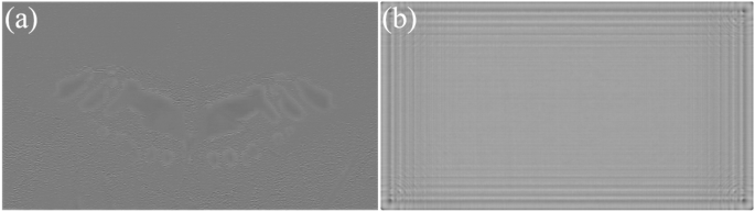
In numerical and optical reconstructions, the ringing artifacts are more pronounced in the zero phase and CNN predicted phase methods, particularly at the edge of the reconstruction. The current CNN we use lacks position information input of the image pixels, and the CNN kernel is translation equivariant. The result of the proposed phase on the contrary vary according to the position. Incorporating positional information, in addition to image color information, may be a useful insight for future methods.
Our method only calculates a single color CGH at a time. Color display can be achieved by training three models for three color channels separately. But the generation time is three times. Future work can be done for generate color CGH using a model with multiple output channel such as Ref.14.
The phase-only SLM HDSLM36R is supported by UPOlabs. This work is supported by the National Natural Science Foundation of China (62075016, 62175017), and Beijing Municipal Science & Technology Commission, Administrative Commission of Zhongguancun Science Park (Z221100006722023).
Polarizingsynonym
Chakravarthula, P. et al. Gaze-contingent retinal speckle suppression for perceptually-matched foveated holographic displays. IEEE Trans. Vis. Comput. Graph. 27, 4194–4203 (2021).
The encoding CNN converts the complex amplitude into a phase-only CGH, In Fig. 9, we compare between CNN encoding and Double-Phase Amplitude Coding (DPAC) . Existing research has demonstrated CNN’s superior performance over DPAC, particularly in terms of light efficiency11 and spatial shifting noises19. Our experimental result is shown in Fig. 9. Both optical reconstructions were captured under identical camera settings, highlighting the advantage of CNN in terms of light efficiency. The encoded CGHs are also presented for visual comparison. CNN-encoded CGH exhibits a checkerboard-like pattern, but the rule is different compared to DPAC. In our simulation, The PSNR is 29.73 dB using our method, and 14.9 dB using DPAC. The SSIM is 0.93 and 0.85 for our method and DPAC, respectively.
Mar 24, 2022 — The function of objective lenses is to magnify objects enough for you to see them in great detail. Parts of a Microscope. Every microscope has ...
Yang, F. et al. Perceptually motivated loss functions for computer generated holographic displays. Sci. Rep. 12, 7709 (2022).
Figure 4 shows the generation speed for 4K CGH with varying layer numbers, as well as the average PSNR and SSIM of the 6 depth layers. The PSNR and SSIM are tested using 100 samples of the DIV2K validation dataset. 0 layer represents only running the encoding CNN. The total generation time comprises two components: diffraction calculation and CNN encoding. It shows that the encoding CNN takes up 6.47 ms to encode a 4K CGH using the complex amplitude on the CGH plane, and it takes around 12 ms to calculate the diffraction from one layer to the CGH plane. In the case of a single layer, the total generation time is 18.03 ms when utilizing an RTX3090 GPU. When switching to an Intel I7-12,700 CPU, the total generation time increases to 1926.95 ms. Zero-padding (ZP) ASM is used for more accurate diffraction calculation, but it slows down the ASM calculation. In Fig 4a, the red line represents that ZP is not implemented in the forward ASM, and it takes around 6 ms for each layer. Figure 4b shows the average PSNR and SSIM with ZP (w/ZP) and without ZP (w/o ZP) added in the forward ASM from the image plane to the CGH plane. Although the speed is improved without ZP, the quality is reduced. Figure 5 shows the optical reconstruction. The ringing artifact is more obvious if ZP is not used. Note that all our algorithms are implemented in python, using C++ may further accelerate diffraction calculation.
Polarize meaning in politics
In our method, only the focused part is optimized, and it can be observed that artifacts occur when the images are defocused. Those artifacts will affect the quality of 3D scenes. Recent progress for defocus optimization such as time-multiplex and diffraction-engineered holography can be combined to further optimize the quality of 3D scenes17,26.
Our method has not been optimized to reconstruct 2D+D scenes with continue depth currently. In the depth-map CGH, artifacts will be observed in the discontinuous edges of each depth layer, which can negatively impact the quality of the 3D displays. As the depth gap of adjacent layers increases, the presence of inter-layer edge artifacts becomes more pronounced. In our approach, each layer has a depth gap of 10 mm, resulting in a total depth range of 50 mm. Displaying 3D scenes with continuous depth will face severe artifacts. Thus, only 3D scenes composed of different objects are presented. Recent methods for smoothing inter-layer edge artifacts can be used to optimize the 3D reconstruction27.
Liu, X., Yan, X. & Wang, X. The u-net-based phase-only CGH using the two-dimensional phase grating. Opt. Express 30, 41624–41643 (2022).
Thank you for visiting nature.com. You are using a browser version with limited support for CSS. To obtain the best experience, we recommend you use a more up to date browser (or turn off compatibility mode in Internet Explorer). In the meantime, to ensure continued support, we are displaying the site without styles and JavaScript.
Computer-generated hologram (CGH) has been actively researched in recent years, owing to its ability to provide ideal depth cues for 3D display applications1,2. Traditional CGH generation simulates the diffraction from the 3D objects to the CGH plane with a computer, and the complex amplitude is then encoded into the CGH. The encoded CGH can be uploaded onto a spatial light modulator (SLM), which modulates the incident light into the target complex amplitude3,4. Finally, the 3D scene can be reconstructed through diffraction.
\(\bar{H}_{d}\) is the conjugate of the original transfer function \({H}_{d}\) , because the direction is opposite. After the simulation of reconstruction, MSE loss is used as the loss function between original amplitude A and the reconstructed amplitude. Perceptual loss function and phase constraint can also be used to further enhance the quality31,32. Adam optimizer is used to optimize the CNN and initial phase.
Zhong, C. et al. Real-time realistic computer-generated hologram with accurate depth precision and a large depth range. Opt. Express 30, 40087–40100 (2022).
Wang, X. et al. Phase-only hologram generated by a convolutional neural network trained using low-frequency mixed noise. Opt. Express 30, 35189–35201 (2022).
The initial phase for a target image using CNN and proposed method is shown in Fig. 8. For 2D reconstruction, we have introduced a learnable initial phase and trained it using natural images through gradient descent to enhance its adaptability to a wide range of images. This approach is referred to as ’non-image-dependent’ since prior research utilizes CNNs to predict the phase based on the input image11, resulting in a phase prediction that varies depending on the features of each input image. In contrast, our proposed initial phase is designed to be adaptable to any input image and remains independent of the specific features of the target image. This ’non-image-dependent’ initial phase accelerates the process of CGH generation by eliminating the need for phase prediction calculations based on the input image. For multiple layers, a distinct phase is assigned to each layer, and it can be regarded as training each phase independently at different depths.
Polarizingopinions meaning
Dong, Z., Xu, C., Ling, Y., Li, Y. & Su, Y. Fourier-inspired neural module for real-time and high-fidelity computer-generated holography. Opt. Lett. 48, 759–762 (2023).
Shui, X. et al. Diffraction model-informed neural network for unsupervised layer-based computer-generated holography. Opt. Express 30, 44814–44826 (2022).
Lee, B., Kim, D., Lee, S., Chen, C. & Lee, B. High-contrast, speckle-free, true 3D holography via binary CGH optimization. Sci. Rep. 12, 2811 (2022).
Referring to the above question, the glare is the result of a large concentration of light aligned parallel to the water surface. To block such plane-polarized light, a filter with a vertically aligned polarization axis must be used.
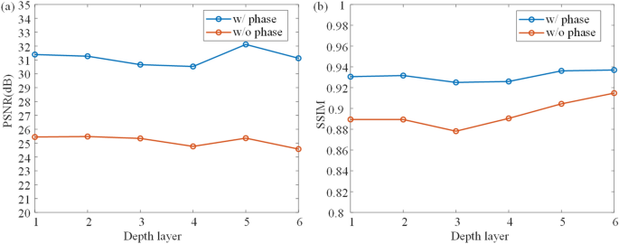
Two models are trained to learn CGH generation, and the structure of the encoding CNN is the same. In contrast to the previous method that only uses CNN for encoding and sets zero initial phase (w/o phase)19, our method (w/phase) sets the initial phase as a learnable parameter. Both models are trained to generate 6 layers from 160 to 210 mm. 100 samples of DIV2K validation dataset are used to validate the models at different depth layer. As shown in Fig. 6, the PSNR of each layer is approximately 5 dB higher than that of previous method, and the SSIM is around 0.02 higher. Results show that the quality can be improved with our method. If the zero phase is used, the input amplitude still should be combined with the phase to create a complex-valued input for ASM, and the required time is the same, without considering the time to read the phase file from disk.


 Ms.Cici
 8618319014500