
Lenses 101 - SEE Eyewear - lenses or lens
So to workaround this clone this git repo, and copy the glTF-Blender-IO/addons/io_scene_gltf2 folder to replace your local blender/x.xx/scripts/addons/io_scene_gltf2 folder.
Data AnalysisPresented to the right are the second-order moment (D4σ) beam widths for the parallel and perpendicular directions as a function of distance from the laser face (denoted as z). Along the parallel direction, we obtained a minimum beam width of 1.5 mm, while along the perpendicular direction, we obtained a minimum beam width of 1.3 mm. The spatial profiles we observed at the two minimum beam width positions, as obtained by the pyroelectric camera, are shown below.
Use a Current Source Specifically Designed for LasersThese lasers should always be used with a high-quality constant current driver specifically designed for use with lasers, such as any current controller listed in the Drivers tab. Lab-grade power supplies will not provide the low current noise required for stable operation, nor will they prevent current spikes that result in immediate and permanent damage.
I can confirm the issue as well. The camera is imported as default 50mm, which is not correct. I have made a three.js WebGL scene and exported it as glTF. In Blender camera FOV is not imported.
Thorlabs manufactures custom and OEM quantum cascade lasers in high volumes. We maintain a broad chip inventory at our Jessup, Maryland laser manufacturing facility and we are accustomed to fulfilling specialized requests.
More details are available on the Custom & OEM Lasers tab. To inquire about pricing and availability, please contact us. A semiconductor specialist will contact you within 24 hours or the next business day.
Heat Build UpLasers are not 100% efficient in forcing electrons to surrender their energy in the form of photons. The electrons that lose their energy as heat cause the temperature of the lasing region to increase.
HHL lasers and TO cans are sealed (although the seal is not hermetic), so the laser chip will not be exposed to air. However, similar dust avoidance precautions should be followed for the window on these packages, since the windows are exposed to the atmosphere.
The electric fields of the perpendicular and parallel components oscillate in planes that are orthogonal to one another. The electric field of the perpendicular component oscillates in a plane perpendicular to the plane of incidence, while the electric field of the parallel component oscillated in the plane of incidence. The polarization of the light beam is the vector sum of the perpendicular and parallel components.
The rollover region includes the peak output power of the laser, which corresponds to a driving current of just under 500 mA in this example. Applying higher drive currents risks damaging the laser.
The light vs. driving current (L-I) curves measured for quantum and interband cascade Lasers (QCLs and ICLs) include a rollover region, which is enclosed by the red box in Figure 2.
If designing your own mounting solution, note that due to these lasers' heat loads, the laser must be mounted in a thermally conductive housing to prevent heat buildup. Heat loads for QCLs and ICLs can be up to 70 W, depending upon the wavelength and package. See the Handling tab for additional information.
The perpendicular and parallel directions are referenced to the plane of incidence, which is illustrated in Figure 1 for a beam reflecting from a surface. Together, the incident ray and the surface normal define the plane of incidence, and the incident and reflected rays are both contained in this plane. The perpendicular direction is normal to the plane of incidence, and the parallel direction is in the plane of incidence.
Operating Limits are Determined by the Heat LoadIdeally, the slope of the L-I curve would be linear above the threshold current, which is around 270 mA in Figure 2. Instead, the slope decreases as the driving current increases, which is due to the effects from the rising temperature of the lasing region. Rollover occurs when the laser is no longer effective in converting additional current to laser light. Instead, the extra driving creates only heat. When the current is high enough, the strong localized heating of the laser region will cause the laser to fail.
Yes, you are right. It is in 2.83 branch like you mentioned and at least import was working correct in my Blender 2.81. Other branches didn't have that change as I checked.
At our semiconductor manufacturing facility in Jessup, Maryland, we build fully packaged mid-IR lasers and gain chips. Our engineering team performs in-house epitaxial growth, wafer fabrication, and laser packaging. We maintain chip inventory from 3 µm to 12 µm, and our vertically integrated facilities are well equipped to fulfill unique requests.
Labels and symbols applied to the perpendicular and parallel components can make it difficult to determine which is which. The table identifies, for a variety of different sets, which label refers to the perpendicular component and which to the parallel.
The 0.85 NA of the collimating lens we used is the largest NA of any lens for this wavelength range that is offered in our catalog. Despite this large NA, we observed lobes in the far field (shown by the figure below) that are consistent with clipping of the laser-emitted light. An ideal measurement would not contain these artifacts.
The specifications for the laser indicate that the typical parallel and perpendicular FWHM divergences are 40° and 60°, respectively. Therefore, as the light propagates, an elliptical beam will result. To collect as much light as possible during the collimation process, consider the larger of these two divergence angles in your calculations (in this case, 60°).
A pyroelectric camera (Spiricon Pyrocam IV) with 80 µm square pixels was scanned along the beam propagation direction, and the beam width was measured along the parallel and perpendicular directions using the second-order moment (D4σ) definition. Hyperbolas were fit to the beam width to extract M2 for each direction. The camera's internal chopper was triggered at 50 Hz since the pyroelectric effect is sensitive to changes in temperature rather than absolute temperature differences. A ZnSe window was present in front of the detector array to help minimize visible light contributions to the signal.
Two-Tab C-MountThe two-tab C-mount measures 6.4 mm x 4.3 mm x 7.9 mm (not including the tabs), provides high thermal conductivity, and can be secured using a 2-56 or M2 screw with the counterbored Ø2.4 mm (Ø0.09") through hole. The drive voltage and current are supplied through the tabs. As measured from the bottom of the C-mount, the emission height of the QCLs is either 7.15 mm or 7.39 mm depending on the chosen laser; the outer dimensions of the C-mounts are the same. All two-tab C-mount lasers sold on this page are electrically isolated from their C-mounts.
Laser Mount CompatibilityThorlabs' LDMC20(/M) C-Mount Laser Mount ships with current and TEC cables for the LDC4005, ITC4001, ITC4002QCL, ITC4005, and ITC4005QCL controllers. To use the LDMC20 with our other controllers, custom cables will be required. For our Ø9 mm TO can QCL we have the LDM90(/M) Laser Mount which is fully compatible with all of the controllers listed in the tables below; however, the mount itself has a limited heat load of 8 W, meaning some QCLs cannot be driven at full power in this mount. If designing your own mounting solution, note that due to these lasers' heat loads, we recommend that they be secured in a thermally conductive housing to prevent heat buildup.
As the temperature of the lasing region increases, more electrons are scattered, and a smaller fraction of them produce light instead of heat. Rising temperatures can also result in changes to the laser's energy levels that make it harder for electrons to emit photons. These processes work together to increase the temperature of the lasing region and to decrease the efficiency with which the laser converts current to laser light.
Proper precautions must be taken when handling and using two-tab C-mount, TO Can, D-mount, or high heat load (HHL) lasers. Otherwise, permanent damage to the device will occur. Members of our Technical Support staff are available to discuss possible operation issues.
This information allows the appropriate collimating lens to be selected. Thorlabs offers a large selection of black diamond aspheric lenses for the mid-IR spectral range. Since this laser emits at 3.80 µm, the best AR coating is our -E coating, which provides Ravg < 0.6% per surface from 3 to 5 µm. The lenses with focal lengths closest to the calculated value of 3.46 mm are our 390036-E (unmounted) or C036TME-E (mounted) Molded Aspheric Lenses, which have f = 4.00 mm. Plugging this focal length back into the equation shown above gives a final beam diameter of 4.62 mm along the major axis.
High-Power Fabry-Perot QCLsFor Fabry-Perot lasers, we can reach multi-watt output power on certain custom orders. The available power depends upon several factors, including the wavelength and the desired package.
Use the tables below to select a compatible controller for our MIR lasers. The first table lists the controllers with which a particular MIR laser is compatible, and the second table contains selected information on each controller. Complete information on each controller is available in its full web presentation. We particularly recommend our ITC4002QCL and ITC4005QCL controllers, which have high compliance voltages of 17 V and 20 V, respectively. Together, these drivers support the current and voltage requirements of our entire line of Mid-IR Lasers.
Some of Thorlabs' DFB quantum and interband cascade lasers are uniquely suited for gas sensing and analysis. Select high heat load QCLs are designed to emit at wavelengths ideal for many gases commonly studied in spectroscopy (see the Spectroscopy tab for more information). These DFB quantum cascade lasers are guaranteed to reach their specified wavelengths within their tuning range and are single wavelength, allowing them to be tuned to specific gas spectra. Thorlabs also sells the ID3250HHLH interband cascade laser and the QD8050CM1 quantum cascade laser, which can be used for methane sensing. A list of these QCLs can be found in the Spectroscopy tab above, and more information is available by clicking on the blue info icons () next to the relevant Item #s below.
The typical operating voltages of our QCLs are 7 - 16 V, while the typical operating voltages of our ICL is 5 V to 8 V. To get L-I-V and spectral measurements of a specific, serial-numbered device, click "Choose Item" next to the part number below, then click on the Docs Icon next to the serial number of the device.
Because quantum cascade lasers (QCLs) and interband cascade lasers (ICLs) have intrinsically large divergence angles, it is necessary to install collimating optics in front of the laser face, as shown in the Collimation tab. We are frequently asked what beam quality can be reasonably expected once the beam has been collimated. This tab presents an M2 measurement we performed using our previous generation 3.80 µm Interband Cascade Laser.
Fabry-Perot LasersFabry-Perot quantum and interband cascade lasers exhibit broadband emission in a range spanning roughly 50 cm-1 to 120 cm-1. The laser's specified output power is the sum over the full spectral bandwidth. Since these lasers have broadband emission, they are well suited for medical imaging, illumination, and microscopy applications. The output spectrum and L-I-V curve of each serial-numbered device, measured by an automated test station, are available below and are also included on a data sheet that ships with the device.
High Heat Load Package with Horizontal EmissionThis package offers an industry-standard pinout and package dimensions. Each package incorporates a built-in thermistor and thermoelectric cooler (TEC) for active temperature management and prolonged laser lifetime, and also includes an internal aspheric lens that collimates the laser's output. As measured from the bottom of the package, the emission height is 12.7 ± 0.13 mm. The emitted light is coupled out of the package through a wedged zinc sulfide (ZnS) window. The output beam of the Distributed Feedback lasers will deviate downward from the normal by either 2.0° ± 1.5° or 2.0° ± 0.75°, while the output beam of the Fabry-Perot lasers will deviate downward from the normal by 2.0° ± 0.6° or 2.0° ± 0.75°. Each laser is electrically isolated from its mount. More information is available at its Distributed Feedback and Fabry-Perot web presentations.
Interbandcascade laser
Distributed Feedback LasersDistributed feedback (DFB) quantum and interband cascade lasers emit at a well-defined center wavelength and provide single transverse mode operation. By tuning the input current and operating temperature, the output frequency can be tuned over a narrow range between 1 cm-1 and 5 cm-1. They are ideal for chemical sensing (see the Spectroscopy tab), optical communications, and other applications. The output spectrum, power, and L-I-V curve of each serial-numbered device, as measured by an automated test station, are available below and are also included on a data sheet with the laser. These quantum and interband cascade lasers are specified for CW output. While pulsed output is possible, this application prohibits current tuning, and performance is not guaranteed. For two-tab C-Mount and D-Mount lasers, some optical power is emitted through the rear facet; this output is not usable in applications.
Additional context Test files are created using ThreeJS editor, adding some cameras and customizing their fov. Then I export to gltf and glb. I see that the fov is stored in the definition of each camera inside the cameras array of gltf file.
D-MountDesigned for OEM customers, our D-mount packages measure 12.0 mm long and have a 2.6 mm emission height. They provide high thermal conductivity and are offered in4.5 mm, 6.0 mm, or 7.5 mm sizes (measured by cavity length). Note that our DFB D-mount is 2.8 mm thick, whereas our FP D-mounts are 2.1 mm thick. Additionally, our D-mount packages are machined with two counterbored slots for mounting. The drive voltage and current are supplied via two large gold contact pads, which are suitable for wire bonding or probe connections. The lasers are electrically isolated from their D-mounts. A built-in thermistor provides real-time temperature measurements for control electronics.
Minimize Physical HandlingAs any interaction with the package carries the risk of contamination and damage, any movement of the laser should be planned in advance and carefully carried out. It is important to avoid mechanical shocks. Dropping the laser package from any height can cause the unit to permanently fail.
Since the output of our MIR lasers is highly divergent, collimating optics are necessary. Aspheric lenses, which are corrected for spherical aberration, are commonly chosen when the desired beam diameter is between 1 - 5 mm. The simple example below illustrates the key specifications to consider when choosing the correct lens for a given application. Please note that lasers in a high heat load (HHL) package are already collimated using a lens integrated into the package.
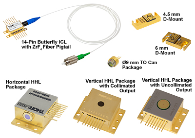
Thorlabs stocks quantum cascade lasers (QCLs) in four packages: a two-tab C-mount recommended for academic and industrial research, D-mount and high heat load packages with horizontal emission intended for OEM applications and system integration, and a Ø9 mm TO can for easy integration into standard mounts. Please see the Handling tab for more tips and information for handling these laser packages. Other packages may be available as custom orders (see the Custom & OEM Lasers tab).
Quantumcascade laserPDF
Each Fabry-Perot quantum and interband cascade laser has an HR-coated back facet. As a custom option, these lasers can be ordered with an AR coating on the front facet; however, the custom item will operate as a gain chip and not as a CW laser. Although these lasers are specified for CW output, they are compatible with pulsed applications provided that the CW max operating current is not exceeded. For more information or to order a Fabry-Perot QCL or ICL with a tested and specified pulsed optical power or other custom features, please contact Tech Support.
Solder can be avoided entirely for two-tab C-mount and TO can lasers by using the LDMC20 or LDM90 laser mounts, respectively. If soldering to the tabs on a two-tab C-mount, solder with the C-mount already attached to a heat sink to avoid unnecessary heating of the laser chip. We do not recommend soldering lasers in TO can packages.
Carefully Make Electrical ConnectionsWhen making electrical connections, care must be taken. The flux fumes created by soldering can cause laser damage, so care must be taken to avoid this.
In order to obtain the hyperbola coefficients a, b, and c for the parallel and perpendicular directions, we fit the discrete beam width measurements along each direction to hyperbolas, as shown in the graph to the right. These coefficients were substituted into Equation 2 (taking λ = 3.781 µm) to yield M2.
DFB QCLs and ICLs are ideal for use in photoacoustic spectroscopy, a technique based on the photoacoustic effect that is able to accurately detect trace gas concentrations for a wide variety of applications. Thorlabs offers an Acoustic Detection Module that can be used with our DFB QCLs and ICLs to build custom QEPAS sensors that target the absorption of a specific gas. We also offer a Quartz-Enhanced Photoacoustic Sensor that targets a methane absorption line to detect trace amounts of methane in a gas.
Ø9 mm TO CanThe Ø9 mm TO can provides high thermal conductivity, and can be easily integrated into a standard mount for high-power TO can laser diodes. This package incorporates an additional copper disk for added heat dissipation. The additional material makes this TO can thicker than standard; however, the laser is still compatible with all Ø9 mm laser mounts. An AR-coated ZnSe window protects the QCL from dust and debris. The drive voltage and current are supplied through the pins. The emission of the QCL is centered in the TO can.
Thorlabs' LCM100(/M) Liquid Cooled Mount is specifically designed to be used with Thorlabs' HHL laser packages. The LCM100(/M) Mount is capable of dissipating heat loads of >140 W at 25 °C, making it an ideal solution for temperature-controlled operation for all of Thorlabs' HHL lasers. For more details on the LCM100(/M) Liquid-Cooled Mount, please see its web presentation here.
I have the same problem. The camera in the gltf has a yFOV value, which is calculated down to the default FocalLength of 50mm after importing the gltf.
DFB QCLs at Custom WavelengthsFor distributed feedback (DFB) lasers, we can deliver a wide range of center wavelengths with user-defined wavelength precision. Our semiconductor specialists will take your application requirements into account when discussing the options with you.
Distributed feedback and Fabry-Perot HHL lasers are compatible with any HHL mount, although cables for HHL packages are typically not rated for the 4.5 A maximum current of the distributed feedback lasers' or the up to 8 A maximum current of the Fabry-Perot lasers' internal thermoelectric coolers. For stable mounting and temperature control of HHL lasers, we recommend using the LCM100(/M) liquid-cooled mount and the CAB4007A or CAB4007B dual LD / TEC connector cables. D-mount lasers require custom mounts. Our ICLs emit a horizontally polarized beam at wavelengths as long as 3.5 µm, while our QCLs emit a vertically polarized beam at wavelengths as long as 11 µm.
Laser cascadevs quantumcascade
For me this worked, you can find the camera fix in io_scene_gltf2/blender/imp/gltf2_blender_camera.py where you can find the added:
Since NALens > NALaser, the 390036-E or C036TME-E lenses will give acceptable beam quality. However, by using the FWHM beam diameter, we have not accounted for a significant fraction of the beam power. A better practice is to use the 1/e2 beam diameter. For a Gaussian beam profile, the 1/e2 beam diameter is approximately equal to 1.7X the FWHM diameter. The 1/e2 beam diameter is therefore a more conservative estimate of the beam size, containing more of the laser's intensity. Using this value significantly reduces far-field diffraction (since less of the incident light is clipped) and increases the power delivered after the lens.A good rule of thumb is to pick a lens with an NA of twice the NA of the laser diode. For example, either the 390037-E or the C037TME-E could be used as these lenses each have an NA of 0.85, which a little less than twice that of our IF3800CM2 laser (NA 0.5). Compared to the first set of lenses we identified, these have a shorter focal length of 1.873 mm, resulting in a smaller final beam diameter of 2.16 mm.
The apparatus we used to determine M2 is shown schematically in the figure above. In order to ensure that our results were rigorous, all data acquisition and analysis were consistent with the ISO11146 standard.
Conversely, heat in the lasing region can be absorbed by electrons. This boost in energy can scatter electrons away from the path leading down the laser's energy steps. Later, scattered electrons typically lose energy as heat, instead of as photons.
The graphs below and photos to the right illustrate some of our custom capabilities. Please visit our semiconductor manufacturing capabilities presentation to learn more.
When polarized light is incident on a surface, it is often described in terms of perpendicular and parallel components. These are orthogonal to each other and the direction in which the light is propagating (Figure 1).
Quantumcascade laserspectroscopy
By clicking “Sign up for GitHub”, you agree to our terms of service and privacy statement. We’ll occasionally send you account related emails.
The maximum drive current and the maximum optical output power of QCLs and ICLs depend on the operating conditions, since these determine the heat load of the lasing region.
Thermally Regulate the LaserTemperature regulation is required to operate the laser for any amount of time. The temperature regulation apparatus should be rated to dissipate the maximum heat load that can be drawn by the laser. For our two-tab C-mount or TO can quantum cascade lasers, this value can be up to 18 W. The LDMC20(/M) C-Mount Laser Mount, which is compatible with our two-tab C-mount package, is rated for >20 W of heat dissipation. The LDM90(/M) Ø9 mm TO Can Laser Mount is only rated for 8 W of heat dissipation, so it cannot operate some quantum cascade lasers at full power. Our DFB D-mount laser's maximum heat load is 7.2 W, our FP D-mount lasers' maximum heat load is 35 W, our HHL FP QCLs have a max heat load of 70 W, and our HHL DFB QCLs and ICL have a maximum heat load of 38 W. The LCM100(/M) Liquid-Cooled Mount is compatible with all standard HHL packages and is capable of dissipating up to 140 W of heat at 25 °C.
The typical operating voltages of our QCLs and ICLs can be as high as 16 V and 8 V, respectively. These lasers do not have built-in monitor photodiodes and must be operated in constant current mode.
Avoid Dust and Other ParticulatesUnlike TO can and butterfly packages, the laser chip of a C-mount or D-mount laser is exposed to air; hence, there is no protection for the delicate laser chip. Contamination of the laser facets must be avoided. Do not blow on the laser or expose it to smoke, dust, oils, or adhesive films. The laser facet is particularly sensitive to dust accumulation. During standard operation, dust can burn onto this facet, which will lead to premature degradation of the laser. If operating a C-mount or D-mount laser for long periods of time outside a cleanroom, it should be sealed in a container to prevent dust accumulation.
For this system, we obtained M2 = 1.2 ± 0.08 in the parallel direction and M2 = 1.3 ± 0.2 in the perpendicular direction. While this is just one example, we believe these results to be representative of well-collimated mid-IR lasers manufactured by Thorlabs, as corroborated by supplementary measurements we have performed in-house.
Distributed Feedback Quantum and Interband Cascade Lasers (DFB QCLs and ICLs) offer many attractive features for spectroscopy. They emit at a single wavelength within the mid-IR, where many gaseous species characteristically absorb. Moreover, their emission wavelength is easily tuned (typical tuning range: 1 - 5 cm-1) by changing the drive current and operating temperature of the laser, making them ideal for isolating narrow gas absorption lines. Finally, quantum cascade lasers offer relatively high output power (typically 40 - 120 mW at rollover current), helping improve measurement sensitivity. ICLs will typically have a low output power, but a far lower power consumption.
As shown by the graph above and to the right, we observed significant astigmatism in the collimated beam: the beam waist of the parallel direction occurred around z = 300 mm, while the beam waist of the perpendicular direction occurred around z = 600 mm. This astigmatism corresponds closely to what is expected for this laser, given that the IF3800CM2 laser is specified with a parallel FWHM beam divergence of 40° and a perpendicular FWHM beam divergence of 60°.
A fan may serve to move the heat away from the TEC and prevent thermal runaway. However, the fan should not blow air on or at the laser itself. Water cooling methods may also be employed for temperature regulation. Although thermal grease is acceptable for TO can and HHL lasers, it should not be used with two-tab C-mount or D-mount lasers, since it can creep, eventually contaminating the laser facet. Pyrolytic graphite is an acceptable alternative to thermal grease for these cases. Solder can also be used to thermally regulate two-tab C-mount lasers, although controlling the thermal resistance at the interface is important for best results. Solder is not recommended for thermal regulation of D-mount or HHL lasers.
Have a question about this project? Sign up for a free GitHub account to open an issue and contact its maintainers and the community.
The back face of the C-mount package and the bottom face of the D-mount or high heat load package is machined flat to make proper thermal contact with a heat sink. Ideally, the heat sink will be actively regulated to ensure proper heat conduction. A Thermoelectric Cooler (TEC) is well suited for this task and can easily be incorporated into any standard PID controller. The HHL package incorporates a suitable TEC.
Quantumcascade laserworking principle
If designing your own mounting solution, note that due to these lasers' heat loads, we recommend that they be secured in a thermally conductive housing with sufficient cooling capacity, either active or passive, to prevent heat buildup. Heat loads for DFB QCLs and ICLs can be up to 38 W. The total heat loads for the Fabry-Perot QCL HHL package can be up to 70 W, although a typical heat load from a Fabry-Perot QCL itself is around 20 W.
Quantumcascade laserapplications
Tuning ExampleTo demonstrate the tunability of these lasers, we measured the center wavelength of a previous-generation QD4580CM1 DFB QCL as a function of drive current, from threshold to near rollover, at 15 °C and 25 °C. Over the entire temperature and drive current range, we obtained center wavelengths from 4.568 µm to 4.586 µm (2189.14 cm-1 to 2180.77 cm-1), spanning a range of 18 nm (8.37 cm-1), with output power ranging from 3.2 mW (at threshold current) to 39.1 mW (at near-rollover current). Since the laser is capable of operating at 35 °C, even broader wavelength tuning is also achievable.
Tunable quantumcascade laser
The previous generation Interband Cascade Laser used for this measurement emitted CW laser light with a center wavelength of 3.781 µm. Our LDMC20 temperature-stabilized mount held the laser's temperature at 25 °C. The output beam was collimated by a C037TME-E lens located immediately downstream of the laser face. This lens was selected because of its large NA of 0.85 (which helped maximize collection of the emitted light) and because of its AR coating (Ravg < 0.6% per surface from 3 µm to 5 µm). We measured 10 mW of output power after the lens.
Mounts, Drivers, and Temperature ControlFor two-tab C-mount quantum cascade lasers, we generally recommend the LDMC20 C-Mount Laser Mount and ITC4002QCL or ITC4005QCL Dual Current / Temperature Controller. This device combination includes all the necessary components to mount, drive, and thermally regulate a two-tab C-mount laser. Other compatible current and temperature controllers are listed in the Drivers tab. The LDM90(/M) Laser Mount along with the ITC4002QCL or ITC4005QCL can be used with the TO can lasers, but the 8 W cooling capacity of the LDM90 may limit the driving current of the lasers.
Below is an image to present the issue. I can manually change the camera lens to Focal Length and convert the FOV value in glTF file to degrees to type in Blender. That will correct the problem, but this should be automatically done by the importer.
The tuning range of individual DFB QCLs and ICLs depends greatly on the actual laser device. Each DFB QCL or ICL is a unique device with its own threshold current, rollover current, and spectrum. Since the wavelength and power of DFB QCLs and ICLs change over the tuning range, operating the lasers near the rollover current is not always desirable in spectroscopy measurements, which require specific wavelengths. The driving current and operating temperature of DFB QCLs and ICLs can be adjusted to change the output signal to the desired wavelength and power.
Avoid StaticSince these lasers are sensitive to electrostatic shock, they should always be handled using standard static avoidance practices.

The CAB4007B Dual Laser / TEC Connector Cable is designed to be used with any of Thorlabs' HHL laser packages or other HHL lasers with compatible pin settings. The CAB4007B connector cable is rated for up to 10 A of laser and TEC current. The CAB4007A Dual Laser / TEC Connector Cable is designed for use with the LCM100(/M) Mount and is rated for up to 11 A of laser and TEC current. For more details on the CAB4007x cables please see the full web presentation here. Please note that third party cables for these packages are typically not rated for the maximum current of the internal thermoelectric cooler.
Although soldering to the leads of our HHL lasers is possible, we generally recommend using cables specifically designed for HHL packages. Thorlabs' CAB4007B LD / TEC cable is specifically designed to connect any standard 10-pin HHL laser package directly to the ITC400xQCL series of laser diode and TEC controllers. The CAB4007A LD / TEC cable can be used to connect an ITC400xQCL controller directly to the LCM100(/M) mount. Please note that third-party cables for high heat load packages are typically not rated for the 4.5 A maximum current of the distributed feedback lasers' or the up to 8 A maximum current of the Fabry-Perot lasers' internal thermoelectric coolers. If soldering to the leads on an HHL package, the maximum soldering temperature and time are 250 °C and 10 seconds, respectively.
QuantumCascade laserprice
Normally Incident LightSince a plane of incidence cannot be defined for normally incident light, this approach cannot be used to unambiguously define perpendicular and parallel components of light. There is limited need to make the distinction, since under conditions of normal incidence the reflectivity is the same for all components of light.

Thorlabs' Quantum and Interband Cascade Lasers (QCLs and ICLs) are composed of multiple quantum well heterostructures and utilize intersubband and interband transitions, respectively, to access the mid-infrared spectral region. They are offered in four packages: a two-tab C-mount, a Ø9 mm TO can, a D-mount, and a high heat load (HHL) package with horizontal emission. The two-tab C-mount and Ø9 mm TO can packages can be easily interfaced to our SM1 lens tubes, 30 mm cage systems, and 60 mm cage systems using the LDMC20 C-Mount Laser Mount or the LDM90 Laser Mount, respectively. The D-mount and HHL packages are intended for OEM applications and systems integration. The HHL package can be mounted Thorlabs' LCM100(/M) Liquid-Cooled Mount for added thermal regulation and protection of the laser diode. Additional information is available in the Packages tab.
Thorlabs' DFB QCLs emit at wavelengths that range from 4.00 to 11.00 µm (2500 cm-1 to 909 cm-1), while our DFB ICLs emit at wavelengths that range from 3.00 to 3.50 µm (3333 cm-1 to 2857 cm-1). If we do not stock the wavelength required for your application, custom wavelengths are available by contacting Tech Support.
An electron must give up some of its energy to drop down to a lower energy level. When an electron descends one of the laser's energy steps, the electron loses energy in the form of a photon. But, the electron can also lose energy by giving it to the semiconductor material as heat, instead of emitting a photon.
A temperature controlled mount is typically necessary to help manage the temperature of the lasing region. But, since the thermal conductivity of the semiconductor material is not high, heat can still build up in the lasing region. As illustrated in Figure 3, the mount temperature affects the peak optical output power but does not prevent rollover.
Laser OperationThese lasers operate by forcing electrons down a controlled series of energy steps, which are created by the laser's semiconductor layer structure and an applied bias voltage. The driving current supplies the electrons.


 Ms.Cici
 8618319014500