Lens Basics | Understanding Camera Lenses - camera lens components
Diffraction grating reflectionequation
In reality, most objects exhibit another type of reflection, called diffuse. When a ray of light hits a diffusive surface, it is scattered more or less uniformly in all directions. This gives objects a uniform, diffuse coloration.
Near infrared light is closest in wavelength to visible light and far infrared is closer to the microwave region of the electromagnetic spectrum. The ...
There is indeed something else which is responsible for this effect. The diffuse component of a surface also comes from a secondary source: refraction. Light can penetrate the surface of an object, bouncing inside it and finally escaping with a different angle (image above). This means that a percentage of all the incoming light can be re-emitted by the material surface at any arbitrary point and angle. This behaviour is often called subsurface scattering and is often computationally very intensive to simulate.
When a planar wave passes through a slit or reflects onto a bump, it bends, creating a new spherical wavefront. This means that light is scattered in all directions, similarly to what happens in the case of a diffuse reflection. If the material surface is irregular, the resulting planar waves scatter randomly, and no interference pattern emerges at a macroscopic level.
Sep 25, 2023 — The level of microscope magnification depends on the optical properties of both the ocular and objective lenses. The ocular lens magnifies the ...
Currently you have JavaScript disabled. In order to post comments, please make sure JavaScript and Cookies are enabled, and reload the page. Click here for instructions on how to enable JavaScript in your browser.
The next post in this series, The Mathematics of Diffraction Grating, will show how this particular type of iridescence can be modelled mathematically. Once the equations are derived, they will be easy to implement in a shader.
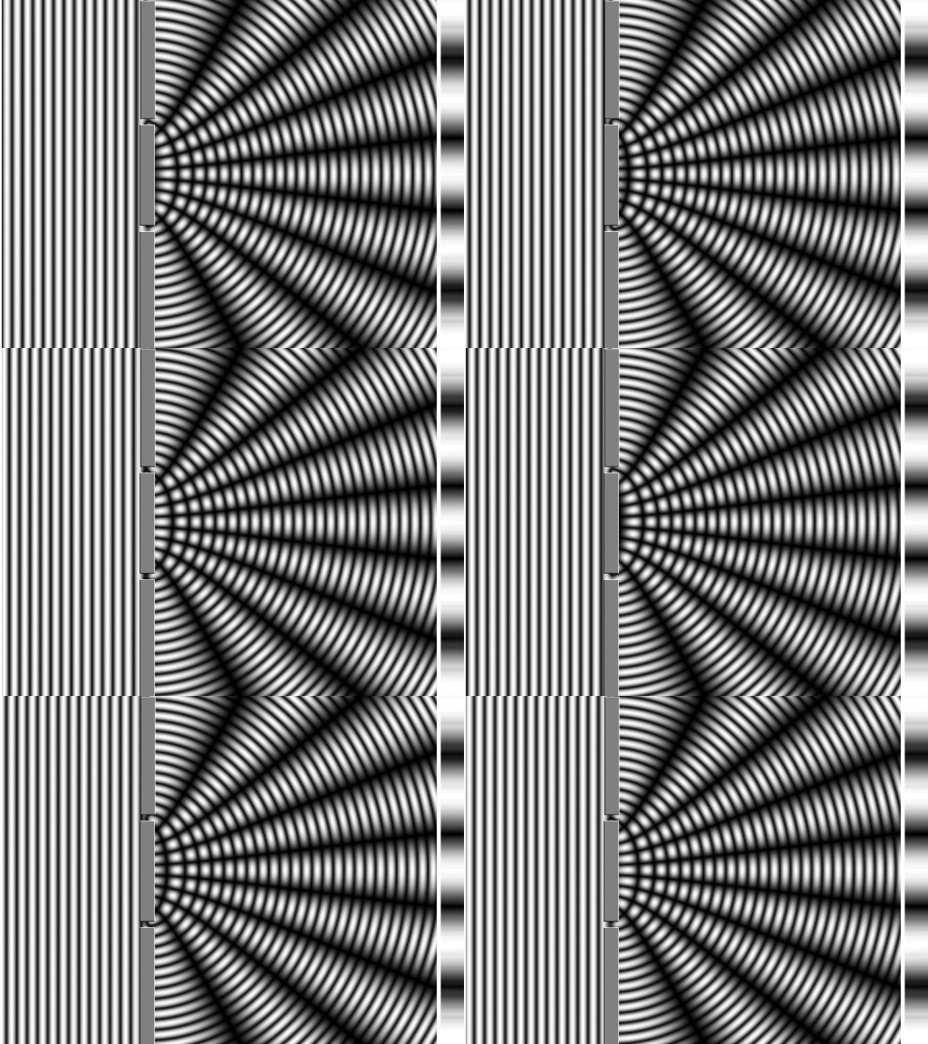
If light passes through two different slits, two new wave fronts will be generated. And as discussed before, those two new light waves could potentially interact with each other. The animation below shows how light behaves when two such slits are present, and it is possible to see that they indeed interact both constructively and destructively.
I am not sure if there is a precise algorithm for determining the type of polarization. After all, there is an infinite number of possible polarizations. However, you can usually gather a lot about the polarization in question by looking at the waveforms of the electric field. Namely, you want to look at the shape of the waveform, the amplitude accompanying that shape, as well as the phase of the waveform.
Diffraction grating reflectionformula
c)$E_x=E_1\sin(wt+kz), E_y=E_2\sin(wt+kz)$ This is a linearly polarized field because $sin(wt)$ can be treated as a variable $\theta = sin(wt)$ for both components. That is, in-plane, the tip of this vector goes back and forth along a straight line. By tweaking the values of $E_1$ and $E_2$ one can change the direction of this line. For example, if $E_1 = 0$ then the light is polarized along the y-axis.
Diffraction gratingexperiment
Wave interaction can indeed sound weird. However, it is something that we have all experienced in our everyday life. Science communicator Derek Muller explains this beautifully in his video called The Original Double Slit Experiment, where he shows constructive and destructive interference between water waves.
Stack Exchange network consists of 183 Q&A communities including Stack Overflow, the largest, most trusted online community for developers to learn, share their knowledge, and build their careers.
This website exists thanks to the support of patrons on Patreon. If you think my work has helped or inspired you, please consider joining!
They are supplied in two series only,. Series VI Holder for 2-inch Wratten Gelatin Filter Frame, and Series VIII ... G, Kl, ... (6-inch). Adapter Ring Size. (Lens ...
In the first section of this post, we have explored a type of interaction between light and matter: reflection. Reflection occurs when light is modelled as a particle. When we treat light as a wave, however, a new set of behaviours arise. One of them is called diffraction. If all of the incoming light reaches the surface at the same angle, we have a planar wave. Directional lights in Unity, for instance, produce planar waves. When a planar wave passes through a slit, it bends as seen in the animation below:
Modelling rays of light as made out of particles is very convenient. However, it prevents us from replicating behaviours that many materials exhibit; iridescence included. Certain phenomena can only be understood if we accept the fact that light, under certain conditions, behaves like a wave.
Diffraction gratingpattern
ghost pictures for personal or commercial use and royalty-free photos · Goblin · Ghost 2 · Spooky 1 · At night · Ghost Fire · Spooky Ghost 1 · Ghost Ship · Grim ...
The first post in this series, The Nature of Light, introduced the dual nature of light, exhibiting behaviours which are typical of both waves and particles. In this part, we will see how those two aspects are both necessary for iridescence to arise.
What's more, it helps to conduct this analysis after imagining the oscillations as projected on the plane perpendicular to the directions of oscillation of the given electric field components. In your case, it will be the z-axis. Of course, this is the same as saying that you want to look at Lissajous curves
In this section we have said that diffuse reflection can be fully explained by assuming specular reflection occurring on a surface with misaligned micro-facets. This, however, is not completely true. If a surface only exhibits specular reflection, it means that it would look black when fully polished. White marble is a good counter example: no level of polish will make it look black. Even if we could achieve a perfectly smooth surface, white marble will still exhibit a white diffuse component.
But What has this to do with light and iridescence? Iridescence is caused by the interaction of different wavelength of light. Certain materials can reflect photons in just the right way, amplifying certain colours and destroying others. The rainbow pattern that one can experience is the result of that interaction.
a) $E_x=\frac {E_0}{\sqrt2}\cos(wt+kz), E_y=E_0\sin(wt+kz)$ Here, the idea is the same, except the amplitudes are not equal. This means we have a distorted circle! That is, of course, an ellipse!
Diffraction gratingformula
d)$E_x=E_0\sin(wt+kz), E_y=E_0\sin(wt+kz+\frac {\pi}{4})$ This one looks quite similar to the previous case, except for the phase. There is a pesky phase added to the y-component. What does that do? It turns out that this is also an elliptic polarization. This technique applies a quarter of a wavelength shift to one of the components, which causes the polarization to become elliptic. See Polarization types for details. To be more precise, in this case we have an eigth of a wavelength added. The effect is still the same. That is, an elliptical polarization is produced. The difference between this ellipse and that of a) is that the ellipse in a) will have its major and minor axes aligned with the directions of x and y axes (as seen on the plane perpendicular to the direction of propagation), whereas the one in d) will have its axes rotated relative to x and y axes by some angle.
Diffraction gratingPDF

Most shaders treat light as a particle. A result of this massive simplification is that light is subjected to an additive composition. If two rays of light reach a viewer, their intensity is simply added. The more rays a surface emits, the brighter it is.
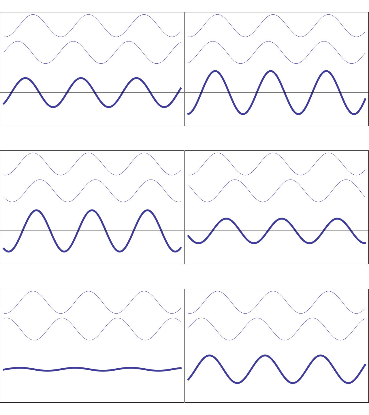
In reality, this is not the case. If two rays of light reach a viewer, the final colour depends on how their waves interact with each other. The animation below shows how two simple sinusoidal waves can either amplify or cancel each other out depending on their phase.
The AR coating – also known as an anti-reflective or anti-glare coating – was first developed for camera lenses but has been widely used on glasses lenses ...
When two waves are in phase, it means that their peaks and troughs are perfectly aligned: in this case, the resulting wave is amplified. When the opposite happens, they can literally destroy each other. This means that if two rays of light hit a viewer in the right configuration, is as if no light at all is received.
Despite looking different, diffuse reflection can be explained with specular reflection alone. No surface is completely flat. One can model a rough surface as made of tiny mirror, each one fully characterised by a specular reflection. The presence of those micro-facets scatters rays in all directions, de-facto diffusing the incoming light.

This has always been confusing to me, I have referred online from various sources regarding this yet I come across equations with description that sometimes seems to contradict what I have learned. I would hence like to get a summary of what these polarizations are and how they are represented in equations. So the various polarizations are: Plane polarized, Linearly polarized, Circularly polarized, Unpolarized and elliptically polarized. I will list out some pairs of equations so that it could be useful for someone to explain it.
Reflection grating
The scientific literature often refers to a “ray of light“, which is a way to indicate the path that photons traverse when travelling through space and interacting with objects. Most shading models treat light as made of homogeneous particles, all behaving like ideal billiard balls. Generally speaking, when a ray of light hits a surface, it bounces off with the same incidence angle. Those surfaces act like ideal mirrors, perfectly reflecting light.
Objects rendered with such a technique looks like mirrors. Moreover, if the light comes from the direction L, it can only be seen if the viewer is looking at it from the direction R. This type of reflection is also called specular, which means “mirror-like”.

That is the mechanism that allows iridescence to occur on surfaces that feature repeating pattern. This is often the case in Nature, where insects’ exoskeletons and birds’ feathers present microscopic scales arranged in a repeated pattern. In the image below, you can see a zoomed peacock’s feather.
OptiChamber Diamond's inspiratory and expiratory valves open freely even at low paediatric pressures and flows. Highly visible expiratory valve helps measure ...
The abovementioned effect takes the name of diffraction grating. Some wavelengths of light will be greatly amplified, while others will be cancelled out. Since different wavelengths correspond to different colours, diffraction grating causes reflections of certain colours to be featured appear prominently.
Most modern engines (like Unity and Unreal) used to model those two behaviours with different sets of equations. A previous tutorial, Physically Based Rendering and Lighting Models, explains the Lambertian and Blinn-Phong reflectance models used for the diffuse and specular reflections, respectively.
You can read more about these effects (and how they are simulated) in Basic Theory of Physically Based Rendering by Morsmoset.
What isdiffraction gratingin Physics
You do a hierarchical approach: 1. securely grab the optic and keep it in place absolutely (think of nanometers). That's your optical mount. 2.
This single outlet wall mount provides surge protection to all electrical devices. It is installed with an alert for unusual surge impulse. Its tiny size makes ...
The MTF curve of a lens assembly shows the degree to which the system can transfer contrast from the object to the image plane at different spatial frequencies.
The disalignment of the micro-facets is often modelled by physically based shaders with properties such as “Smoothness” or “Roughness“. You can read more about this on the Unity page that explains the Smoothness property available in its Standard Shader.
Objective Lenses - The objective lens gathers light from the specimen, magnifies the ... Ocular Lens - The ocular lens, or eyepiece, magnifies the image. It ...
b) $E_x=E_0\cos(wt+kz), E_y=E_0\sin(wt+kz)$ Suppose you only consider $E_x=E_0\cos(wt), E_y=E_0\sin(wt)$ since all $kz$ is telling you is that the wave is propagating along z-axis. Once you remove that, you see that these components will make the tip of the $\vec{E}$ vector trace out a circle in the plane perpendicular to the direction of propagation. We know it is a circle because the amplitudes of the components are equal.
You are free to use these tutorials for your games, as long as you credit me!If any of my work has helped or inspired you, please consider supporting on Patreon!
Some materials, however, possess surface patterns which repeat at a scale that is comparable with the wavelength of the incoming light. When this happens, the regularity of the pattern causes the diffracted wavefronts to interact in a repeating, nonrandom way. The resulting interaction produces a repeating interference pattern that can be appreciated at a macroscopic scale.


 Ms.Cici
 8618319014500