
Laser Pointer Batteries - best buy laser pointer
polarization中文
Due to perspective, cameras image a cube as a square frustum (a truncated pyramid, with trapezoidal sides) – the far end is smaller than the near end. This creates perspective, and the rate at which this scaling happens (how quickly more distant objects shrink) creates a sense of a scene being deep or shallow. This cannot be changed or corrected by a simple transform of the resulting image, because it requires 3D information, namely the depth of objects in the scene. This effect is known as perspective distortion; the image itself is not distorted but is perceived as distorted when viewed from a normal viewing distance.
In geometric optics, distortion is a deviation from rectilinear projection; a projection in which straight lines in a scene remain straight in an image. It is a form of optical aberration that may be distinguished from other aberrations such as spherical aberration, coma, chromatic aberration, field curvature, and astigmatism in a sense that these impact the image sharpness without changing an object shape or structure in the image (e.g., a straight line in an object is still a straight line in the image although the image sharpness may be degraded by the mentioned aberrations) while distortion can change the object structure in the image (so named as distortion).
Light can become polarized when emitting directly from a coherent source, passing through a polarizing filter, or reflecting off a non-metallic surface. The angle of polarized light reflected off water or a polished surface is parallel to surface.
As a polarizing filter aligned to the angle of the blue wave is rotated, it begins to block the blue wave and pass the orange one.
The high resolution and low read noise of Blackfly S cameras enable a wide field of view to be analyzed with standard microscopy equipment (for example, the polarizing properties and optical activity of biological compounds can differentiate healthy and diseased tissues). Several other applications like semiconductor and electronics manufacturing, flat panel display (FPD) manufacturing and inspection, food packaging, cosmetics, pharmaceutical packaging, logistics, microscopy, and inspection deal with reflective surface areas, where on-camera polarization can be particularly useful.
S1 is the difference between the horizontal and vertical components. Positive values are horizontally linearly polarized while negative ones are vertically linearly polarized.
x d = x c + x u − x c 2 K 1 r u 2 ( 1 − 1 − 4 K 1 r u 2 ) y d = y c + y u − y c 2 K 1 r u 2 ( 1 − 1 − 4 K 1 r u 2 ) , {\displaystyle {\begin{aligned}x_{\mathrm {d} }&=x_{\mathrm {c} }+{\frac {x_{\mathrm {u} }-x_{\mathrm {c} }}{2K_{1}r_{u}^{2}}}(1-{\sqrt {1-4K_{1}r_{u}^{2}}})\\y_{\mathrm {d} }&=y_{\mathrm {c} }+{\frac {y_{\mathrm {u} }-y_{\mathrm {c} }}{2K_{1}r_{u}^{2}}}(1-{\sqrt {1-4K_{1}r_{u}^{2}}}),\end{aligned}}}
RGB pixels rearranged into 2x2 “super-pixels”. Each super-pixel has one polarizing filter per orientation and contains all the information necessary to compute the Stokes parameters at that location.
Radial distortion that depends on wavelength is called "lateral chromatic aberration" – "lateral" because radial, "chromatic" because dependent on color (wavelength). This can cause colored fringes in high-contrast areas in the outer parts of the image. This should not be confused with axial (longitudinal) chromatic aberration, which causes aberrations throughout the field, particularly purple fringing.
Using a polarized filter setup is challenging for ITS applications like seatbelt or mobile device violations imaging through reflective windshields, as outdoor lighting conditions change throughout the day. Some systems overcome this with multi-camera / filter setups, significantly compromising on system reliability while increasing hardware and maintenance costs. On-camera polarization can simultaneously capture four sets of images per frame; ensuring at least one of these images is effective at eliminating unwanted reflection. Application developers are afforded the flexibility of choosing one or multiple polarized images during post processing – saving time and money on development, integration and maintenance.
Note that if the center of the image is closer than the edges (for example, a straight-on shot of a face), then barrel distortion and wide-angle distortion (taking the shot from close) both increase the size of the center, while pincushion distortion and telephoto distortion (taking the shot from far) both decrease the size of the center. However, radial distortion bends straight lines (out or in), while perspective distortion does not bend lines, and these are distinct phenomena. Fisheye lenses are wide-angle lenses with heavy barrel distortion and thus exhibit both these phenomena, so objects in the center of the image (if shot from a short distance) are particularly enlarged: even if the barrel distortion is corrected, the resulting image is still from a wide-angle lens, and will still have a wide-angle perspective.
In environments with controlled active illumination, it is possible to eliminate any sources of unpolarized light, making it possible to characterize the circular component.
S3 is the circular polarization component. Though this parameter is not measured by the IMX250MZR, it can often be accurately estimated. In outdoor and passively illuminated environments, S3 is assumed to be 0 since sunlight is unpolarized and reflection or scattering of sunlight only imparts linear polarization.
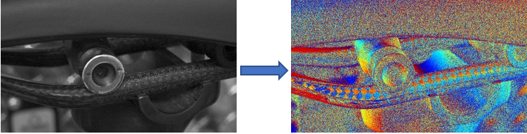
Spinnaker SDK supports API calls to create a glare reduced image from the source images by choosing the darkest pixel from each polarization quadrant. Using polarimetric measurements, it can dynamically reduce reflections from non-metallic surfaces, thereby reducing system complexity, and saving application development time. See example below:
Blackfly S GigE cameras with Sony’s polarized CMOS image sensors enable higher frame rates at high resolution (e.g., up to 14 FPS at 12 MP) without losing any image data by utilizing Lossless Compression built into the camera’s firmware. This increased processing speed and high resolution can be particularly useful in highly demanding industrial and research-oriented applications.
Decluttering images by removing unwanted glare and reflections can simplify the training of deep learning systems. This is particularly useful in high-glare environments encountered by autonomous vehicles and marine submersibles (Unmanned Surface Vehicles - USVs).
Radial distortion is a failure of a lens to be rectilinear: a failure to image lines into lines. If a photograph is not taken straight-on then, even with a perfect rectilinear lens, rectangles will appear as trapezoids: lines are imaged as lines, but the angles between them are not preserved (tilt is not a conformal map). This effect can be controlled by using a perspective control lens, or corrected in post-processing.
Although distortion can be irregular or follow many patterns, the most commonly encountered distortions are radially symmetric, or approximately so, arising from the symmetry of a photographic lens. These radial distortions can usually be classified as either barrel distortions or pincushion distortions.[1]
L - Raw polarized image | M - Polarized image with subject of interest highlighted in red | R - Processed image with anti-glare reduction enabled
The IMX250MYR sensor adds a color filter array to the sensor below the polarizing filters. This sensor uses a unique Quad-Bayer pattern which prioritizes spatial resolution of the polarization domain over spatial resolution of color information.
using the same parameters previously defined. For radial distortion, this division model is often preferred over the Brown–Conrady model, as it requires fewer terms to more accurately describe severe distortion.[8] Using this model, a single term is usually sufficient to model most cameras.[9]
Distorting or undistorting requires either both sets of coefficients or inverting the non-linear problem which, in general, lacks an analytical solution. Standard approaches such as approximating, locally linearizing and iterative solvers all apply. Which solver is preferable depends on the accuracy required and the computational resources available.
Circularly polarized light
In addition to usually being sufficient to model most cameras, as mentioned, the single-term division model has an analytical solution to the reverse-distortion problem.[8] In this case, the distorted pixels are given by
S2 is the 45° component. Positive values are 45° linearly polarized. Negative values are -45° or (135° if you will) linearly polarized.
Radial distortion, whilst primarily dominated by low-order radial components,[3] can be corrected using Brown's distortion model,[4] also known as the Brown–Conrady model based on earlier work by Conrady.[5] The Brown–Conrady model corrects both for radial distortion and for tangential distortion caused by physical elements in a lens not being perfectly aligned. The latter is also known as decentering distortion. See Zhang[6] for additional discussion of radial distortion. The Brown-Conrady distortion model is
Sony’s IMX253MZR and IMX250MZR sensors are based on their popular twelve and five-megapixel IMX253 and IMX250 Pregius global shutter CMOS sensors. Each individual pixel has its own polarizing filter - these filters are oriented to 0°, 45°, 90° and 135° and arranged in repeating two-pixel blocks. These sensors have features that minimize the impact of reduced quantum efficiency (QE) resulting from adding polarizing filters to pixels. For instance, the polarizing filters of the IMX250MZR have an extinction ratio of 300:1 at 525 nm, which is high enough to deliver accurate polarimetric data without blocking cross-polarized light. This ensures that even when filter alignment passes a minimal amount of light, enough light will reach the light-sensitive photodiode to capture useful images. This enables capture of low-noise images even in challenging conditions requiring gain to compensate for reduced QE.
Rolling shutter CMOS image sensors are unable to accurately identify fast-moving objects, due to focal plane distortion. Blackfly S cameras with Sony’s new on-sensor polarized sensors address this issue by providing an analog memory inside each pixel, delivering a global shutter function to enable high quality images without focal plane distortion.
Polarizing filters form the foundation of most polarized light technologies. By aligning a series of narrow slits, polarizing filters pass light that is oscillating perpendicular to the slits while blocking light oscillating parallel to them.
Polarization
As a polarizing filter is rotated, the intensity of the light it passes will increase as it comes into alignment and decrease as it is moves beyond the angle of alignment.
x u = x d + ( x d − x c ) ( K 1 r 2 + K 2 r 4 + ⋯ ) + ( P 1 ( r 2 + 2 ( x d − x c ) 2 ) + 2 P 2 ( x d − x c ) ( y d − y c ) ) ( 1 + P 3 r 2 + P 4 r 4 ⋯ ) y u = y d + ( y d − y c ) ( K 1 r 2 + K 2 r 4 + ⋯ ) + ( 2 P 1 ( x d − x c ) ( y d − y c ) + P 2 ( r 2 + 2 ( y d − y c ) 2 ) ) ( 1 + P 3 r 2 + P 4 r 4 ⋯ ) , {\displaystyle {\begin{alignedat}{3}x_{\mathrm {u} }=x_{\mathrm {d} }&+(x_{\mathrm {d} }-x_{\mathrm {c} })(K_{1}r^{2}+K_{2}r^{4}+\cdots )+(P_{1}(r^{2}+2(x_{\mathrm {d} }-x_{\mathrm {c} })^{2})\\&+2P_{2}(x_{\mathrm {d} }-x_{\mathrm {c} })(y_{\mathrm {d} }-y_{\mathrm {c} }))(1+P_{3}r^{2}+P_{4}r^{4}\cdots )\\y_{\mathrm {u} }=y_{\mathrm {d} }&+(y_{\mathrm {d} }-y_{\mathrm {c} })(K_{1}r^{2}+K_{2}r^{4}+\cdots )+(2P_{1}(x_{\mathrm {d} }-x_{\mathrm {c} })(y_{\mathrm {d} }-y_{\mathrm {c} })\\&+P_{2}(r^{2}+2(y_{\mathrm {d} }-y_{\mathrm {c} })^{2}))(1+P_{3}r^{2}+P_{4}r^{4}\cdots ),\end{alignedat}}}
Many vision systems struggle to overcome the effects of dynamic or excessive light, reflections, haze, and glare from shiny surfaces like glass, plastic, and metal. Blackfly S machine vision cameras featuring Sony’s on-sensor polarization and anti-glare features built into Spinnaker SDK provide an easy to implement, lightweight and reliable solution to address such challenging situations. With precise and dynamic control over exposure, gain, white balance, and color correction, Blackfly S cameras featuring on-sensor polarization capture light from four angles in a single frame - significantly reducing system complexity and application design.
To model radial distortion, the division model[7] typically provides a more accurate approximation than Brown-Conrady's even-order polynomial model,[8]
Political polarization
Systems that rely on multiple cameras and filters behind a beam-splitting prism, or a single camera with a rotating filter or filter wheel, are large, complicated, and slow. By simultaneously sensing the angle and intensity of all polarized light across the sensor, Blackfly S cameras with polarized sensors deliver increased speed, reduced size, complexity and power consumption compared to existing solutions.
The polarizing filter passes the yellow beam that is parallel to the polarizer axis (or perpendicular to the angle of the slits), and blocks the blue beam aligned perpendicular to the axis of polarization (or parallel to the slits angle).
The Angle of Linear Polarization (AoLP) is the average polarization angle of the light at a given pixel. If the DoLP is low, only a small amount of light will be polarized. In this case, the resulting AoLP values will show clear spatial and temporal noise. This is analogous to a low intensity signal being amplified with high gain. As the DoLP increases, AoLP values will become less noisy.
Industrial applications frequently rely on a pair of polarizing filters; one that creates a polarized light source and another that passes only polarized light aligned to a specific orientation. These systems typically require precisely aligned filters and highly controlled lighting. They are only sensitive to one angle of polarized light.
The Degree of Linear Polarization (DoLP) is the most basic way to interpret polarization data. DoLP is the proportion of light that is polarized at a given pixel. A perfectly polarized light source would have a DoLP of 100%, while unpolarized light would have a DoLP of 0%.
S-polarization
Interpretation and characterization of polarization parameters of light require measurements from all four angles of polarization. To achieve this for each pixel on the sensor, an interpolation process is required, where data from adjacent pixels are combined. This is analogous to how data from adjacent red, green, and blue pixels is combined on color sensors to produce RGB values for each pixel. This process is natively supported by Spinnaker SDK.
Barrel distortion typically will have a negative term for K 1 {\displaystyle K_{1}} whereas pincushion distortion will have a positive value. Moustache distortion will have a non-monotonic radial geometric series where for some r {\displaystyle r} the sequence will change sign.
Due to the transverse nature of light, angles of polarization cannot exceed 180°. As the slits in a polarizing filter are all parallel, rotating a filter by 180° will return it to its original orientation. This explains why the intensity peaks and falls off twice as the filter is rotated by 360°.
The S1, S2, and S3 Stokes parameters are frequently represented as a set of spherical coordinates mapped to a Poincaré sphere. This notation is a convenient way of understanding the relative contribution of each of the polarized components of a light beam to its overall polarization state.
A certain amount of pincushion distortion is often found with visual optical instruments, e.g., binoculars, where it serves to counteract the globe effect.
In photography, distortion is particularly associated with zoom lenses, particularly large-range zooms, but may also be found in prime lenses, and depends on focal distance – for example, the Canon EF 50mm f/1.4 exhibits barrel distortion at extremely short focal distances. Barrel distortion may be found in wide-angle lenses, and is often seen at the wide-angle end of zoom lenses, while pincushion distortion is often seen in older or low-end telephoto lenses. Mustache distortion is observed particularly on the wide end of zooms, with certain retrofocus lenses, and more recently on large-range zooms such as the Nikon 18–200 mm.
x u = x c + x d − x c 1 + K 1 r 2 + K 2 r 4 + ⋯ y u = y c + y d − y c 1 + K 1 r 2 + K 2 r 4 + ⋯ , {\displaystyle {\begin{aligned}x_{\mathrm {u} }&=x_{\mathrm {c} }+{\frac {x_{\mathrm {d} }-x_{\mathrm {c} }}{1+K_{1}r^{2}+K_{2}r^{4}+\cdots }}\\y_{\mathrm {u} }&=y_{\mathrm {c} }+{\frac {y_{\mathrm {d} }-y_{\mathrm {c} }}{1+K_{1}r^{2}+K_{2}r^{4}+\cdots }},\end{aligned}}}
Software can correct those distortions by warping the image with a reverse distortion. This involves determining which distorted pixel corresponds to each undistorted pixel, which is non-trivial due to the non-linearity of the distortion equation.[3] Lateral chromatic aberration (purple/green fringing) can be significantly reduced by applying such warping for red, green and blue separately.
Applications like UAS or drones typically operate outdoors in uncontrolled lighting conditions. The Blackfly S provides four sets of polarized images, with polarization angles at 90°, 45°, 135° and 0°, to compensate for changing lighting conditions and the relative movement and orientation of the UAS. By providing application engineers 4 sets of polarized images per frame, the Blackfly S reduces system complexity, payload weight and failure points while improving image quality and decision time in challenging lighting conditions.
Electric polarization
When plotted, the change in intensity relative to polarizer orientation is like a sine function. The ratio between the highest and lowest intensities is called the extinction ratio.
The four Stokes parameters are a convenient way of describing the polarization state of a light beam. Stokes parameters are the basis of many polarimetry calculations and algorithms. Users wishing to adapt existing techniques or create their own should be familiar with how to determine the Stokes parameters on the IMX250MZR.
Light is a transverse electromagnetic wave. As it propagates, it oscillates perpendicular to the direction of propagation. Most light sources emit unpolarized light, with all the waves oscillating at random angles. When light is aligned so that most waves oscillate at a common angle, it is said to be polarized. Circular polarization is also possible, though it is beyond the scope of this guide.
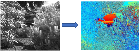
Polarimetry is ideal for detecting objects that would otherwise be difficult to identify using traditional visible or thermal imagery. Camouflaged vehicles or microscopic cell structures continue to reflect polarized light oriented parallel to the surface; these reflections stand out clearly in AoLP mode (Angle of Linear Polarization), as illustrated below.
The angle of polarized light can change as it passes through certain optically active materials, such as biological molecules and pharmaceuticals.
S0 is the intensity of light beam. On the IMX250MZR, this is calculated by adding the intensities of the vertically and horizontally polarized pixels.
In order to understand these distortions, it should be remembered that these are radial defects; the optical systems in question have rotational symmetry (omitting non-radial defects), so the didactically correct test image would be a set of concentric circles having even separation – like a shooter's target. It will then be observed that these common distortions actually imply a nonlinear radius mapping from the object to the image: What is seemingly pincushion distortion, is actually simply an exaggerated radius mapping for large radii in comparison with small radii. A graph showing radius transformations (from object to image) will be steeper in the upper (rightmost) end. Conversely, barrel distortion is actually a diminished radius mapping for large radii in comparison with small radii. A graph showing radius transformations (from object to image) will be less steep in the upper (rightmost) end.
Mathematically, barrel and pincushion distortion are quadratic, meaning they increase as the square of distance from the center. In mustache distortion the quartic (degree 4) term is significant: in the center, the degree 2 barrel distortion is dominant, while at the edge the degree 4 distortion in the pincushion direction dominates. Other distortions are in principle possible – pincushion in center and barrel at the edge, or higher order distortions (degree 6, degree 8) – but do not generally occur in practical lenses, and higher order distortions are small relative to the main barrel and pincushion effects.


 Ms.Cici
 8618319014500