
Laser and IPL safety glasses for Sale | Parts | 1-888-252-2219 - laser safety glasses
In some instances, we do away with the transition band completely when defining band-stop filters. In this case, the stopband will equal the bandwidth, which is calculated at the band between the two cutoff frequencies fL and fH.
Long pass filterfluorescence
Remember that the impedance is made of the resistance and reactance components of the circuit. The typical impedance formula is:
Now let's have a look at a Butterworth low-pass filter with orders 1 through 5 in the following image. Envision this filter ramping down past the low cutoff frequency of the BSF, remembering, again, that the order of the BSF will be double that of the matching order of the HPF and LPF:
Note that resistors generally have greater losses than capacitors and so with the twin-T circuit we'll have uneven gain at either side of the notch frequency.
Notice how the cutoff frequency (which is at 1 kHz for each graph) takes place at the -3 dB attenuation point regardless of filter order.
Hiss in the high-end, if it's concentrated within a specific band of frequencies, can be eliminated with a notch filter will eliminating all of the high-end (as would be the case when using the typical low-pass filter for the job).
Note, too, that the standard Butterworth filter holds the above relationship between order and roll-off rate true. Other filter types offer different relationships. More on this later.
Note that the audible frequency range for humans is universally accepted to be from 20 Hz to 20,000 Hz. For that reason, many audio signals will also be roughly in and around this range.
These frequencies can also be rumbling in a specific frequency band in the low-end or electromagnetic interference (particularly the dreaded 60-cycle hum). However, high-pass filters are typically used for low-end rumble and low-end EMI.
The common twin-T notch filter circuit is as follows (the LPF is made of R1 and C1 and the HPF is made of R2 and C2 while the additional R1 and C2 act to further narrow the notch):
Now, a bell curve/peak filter is generally used with dynamic EQ-style de-essing, which will bring the specific frequencies down by a defined amount as the energy within the band surpasses a set threshold. However, we can achieve “harder” de-essing by notching the sibilant frequencies completely as the energy surpasses a set threshold.
The acoustic environment in question will play a major role in determining which frequencies will begin feeding back first (at lower thresholds). This often has to do with the natural resonances of an acoustic space and the standing waves that come as a result.
To learn more about microphone feedback, check out my article 12 Methods To Prevent & Eliminate Microphone/Audio Feedback.
Band-stop/notch filters aren't the most popular in this situation but can be used in this context to completely eliminate a very narrow band of frequencies (or bands of frequencies) that are particularly prone to causing feedback.
Perhaps the most obvious difference between analog and digital filters is that analog filters are made of analog components (resistors, capacitors, operational amplifiers, etc.) and filter analog audio signals while digital filters are either coded in software or embedded in digital circuits and act on digital audio signals.
In most band-stop filter designs, there will be an equal number of reactive components in the high-pass and low-pass sections of the circuit. This would mean that, generally speaking, band-stop filters will usually have an even number order. Of course, they can be designed in other ways but these designs are less common.
Mid-side (M/S) processing may not be the most popular style of processing when it comes to stereophonic audio, but it’s certainly effective in some situations. Combine this fact with the power of equalization, and it makes perfect sense that mid-side EQs would exist in the realm of audio technology. In this article, we’ll describe mid-side…
This type of filter works great as a band-reject-style BSF, offering superb performance and a width stopband/bandwidth. We can add additional resistor-capacitor pairs to the LPF and HPF portions of the circuit to steepen the roll-offs of the band-reject filter.
What I can say about the Q factor is, regardless of how a manufacturer defines “Q”, increasing this parameter in a band-stop filter will reduce the stopband/bandwidth while decreasing this parameter will increase the stopband/bandwidth.
Notice how both cutoff frequencies are at the -3 dB point of their respective roll-offs. As we've discussed briefly, this is the frequency at which the filter cuts the power of the signal in half. This definition of cutoff frequency is used in band-stop, low-pass, high-pass, band-pass and other filters.
Eliminating the voltage divider (R3 and R4) and connecting the junction of R2 and C1 would yield maximum attenuation at the notch frequency.
In this graph, we can see how the BSF's lower passband gradually rolls off above the low cutoff (fL) and how the BSF's high passband gradually rolls off below the high cutoff (fH). The attenuation continues to increases until the two roll-offs meet at the centre frequency (fC).
As was the case with the basic band-reject filter, we have the first-order low-pass filter on top (made of R1 and C1) and the first-order high-pass filter on the bottom (made of R2 and C2).
However, in many cases, the band-stop filter is its own unique circuit (or script of code). The rest of this article will focus on actual band-stop filter circuits and designs.
The Q factor of a band-stop filter is defined as the reciprocal of the filter's bandwidth/passband. Q is a dimensionless unit. Again, the bandwidth of a band-stop filter is defined as the range between the two cutoff frequencies (fH – fL).
Passive filters like this are also at the disadvantage of relying on the passive components to maintain an output impedance. An op-amp can effectively drop the output impedance to improve signal transfer between the filter and the load (the next audio device). Passive circuits do not have this luxury.
Know that the study of electronic filters is a study that goes deep. The aim of this article is to provide a thorough overview of notch filters in audio rather than a complete guide to all possible band-reject filters. That being said, there's a lot of information here and I'd recommend using the table of contents to jump around to what you're interested in learning.
The addition of an “extra” R1 and C2 deepen the notch, producing a fixed Q value of 0.25 and roll-offs in the order of -12dB.
Shortpass filter
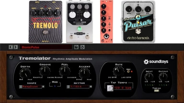
The tremolo effect is a staple in audio production, known for adding rhythmic modulation to sounds. This classic effect, characterized by rapid changes in volume, has been used across genres to create dynamic textures and captivating sonic landscapes. It translates very well to audio signals, where electrical circuits and digital programs can achieve the same…
The lower passband is technically defined as the band between the low cutoff frequency and 0 Hz. Conversely, the high passband is technically defined as the band between the high cutoff frequency and ∞ Hz.
Frequency is measured in Hertz (Hz), which refer to cycles per second. Audio signals are AC signals and, therefore, have frequency components. When audio signals are converted to sound waves, we are able to hear the information of the audio signal. Since the human hearing range is universally accepted to be 20 Hz – 20,000 Hz, most audio signals will have information within this range (so as to avoid having an abundance of imperceivable information).
To learn more about band-pass filters and EQ more generally, check out the following articles:• Audio EQ: What Is A Band-Pass Filter & How Do BPFs Work?• Complete Guide To Audio Equalization & EQ Hardware/Software
Since analog band-stop filters (and the digital filters that aim to recreate them digitally), at the very least, second-order filters, they will, at the very least, have 180º of phase-shift.
With modern digital signal processing (DSP) and computer processing power, it's possible to design incredibly precise and versatile digital filters. Band-stop filters can be designed to act, essentially, as ideal filters in audio devices including, particularly, digital equalizers.
Active and passive filters differ in one key way: active filters have active components that require power to function and passive filters do not.
Long passvs bandpassfilter
A linear phase EQ (which will almost certainly always have band-stop filter options) effectively eliminates any phase-shift within the audio processor.
When dealing with audio filters and EQ, we're obviously affecting the frequency-dependent amplitude of the audio signal. In the majority of cases (excluding linear phase EQs/filters), we're also affecting the frequency-dependent phase of the audio signal.
In the above circuit, we have the first-order low-pass filter on top (made of R1 and C1) and the first-order high-pass filter on the bottom (made of R2 and C2).
But which frequencies are affected and which arent is another question. The passband can be found by finding the cutoff frequency with the following equation:
As a band-stop attenuates the output of certain frequencies by varying amounts, it will also shift the phase of the frequencies by varying amounts.
Here's a short table to recap the differences between analog and digital band-stop filters discussed in this section: Analog Audio BSFDigital Audio BSF Filters analog (continuous-time) audio signalsFilters digital (discrete-time) audio signals Made of analog componentsEmbedded in digital chips (with adders, subtractors, delays, etc.), or; Coded into software Limited in functionality & adaptabilityMore versatile in programming More sensitive to environmental changesLess sensitive to environmental changes Analog components introduce thermal noiseQuantization introduces digital noise Higher manufacturing costLower manufacturing cost
We can add resistor-capacitor pairs to the circuit above in an attempt to steepen the roll-off rate of the filter. However, we'd be doing so at the expense of output amplitude and signal-to-noise ratio as each component will drain some amount of power and add some amount of noise.
What is a finite impulse response filter in audio? An FIR filter is a filter (analog or digital, though nearly always digital) that works with an impulse response of finite duration, settling to zero within some amount of time. It lends itself well to linear phase EQ.
What is a band-pass filter in audio? A band-pass filter “passes” a band of frequencies (a defined range above a low cutoff and below a high cutoff) while progressively attenuating frequencies below the low cutoff and above the high cutoff.
The EQs that will offer a Q factor control on the band-stop filter will typically have a graphic to show you how the filter is affecting the signal.
As an additional equation, we can calculate the aforementioned phase-shift of an RC high-pass filter with the following equation:
Rather than using analog components (capacitors, resistors, operational amplifiers, etc.), digital circuits will be embedded in digital chips (with adders, subtractors, delays, etc.) or, alternatively, be programmed into audio plugins.
Here's a short table to recap the differences between active and passive band-stop filters discussed in this section: Active Audio BSFPassive Audio BSF Requires powerDoes not require power Includes active and passive components (including op-amps)Only includes passive components (resistors, capacitors, etc.) Offers amplification above unity gain (boosts in addition to cuts)Cannot offer amplification above unity gain (cuts only) Possibility of even gain in notch filter roll-offsUneven gain in notch filter roll-offs Low output impedance (load-independent performance)Higher output impedance (load-dependent performance) Higher manufacturing costLower manufacturing cost
The transition bands will happen between the cutoff frequencies and the shared stopband (if we define a stopband at all).
Have any thoughts, questions or concerns? I invite you to add them to the comment section at the bottom of the page! I'd love to hear your insights and inquiries and will do my best to add to the conversation. Thanks!
If we recall our discussion on band-stop filter Q factor, we can remember that there are basically two types of band-stop filters used in audio:
So we know that a band-stop filter will effectively pass all frequencies except for a specified band defined between a low cutoff frequency and a high cutoff frequency.
Vibrato is a popular and powerful musical technique implemented naturally by singers and available to other acoustic instruments, and it’s also available electrically as an audio effect. In this article, we’ll primarily discuss vibrato as an audio effect and consider its origins as an acoustic pitch modulation technique. To further our understanding, we’ll also consider…
Of course, a voltage divider acts on DC voltage and audio signals are AC. However, the idea can be translated to AC voltage in our simple RC high-pass filter. In order to translate the circuit to AC signals, we must consider impedance (Z) and not only resistance.
However, because band-stop filters are generally only tasked with cutting frequencies, they can still work just fine in circuits that would benefit from them (such as passive EQ units).
A linear phase EQ (and band-stop filter) uses digital signal processing (DSP) to analyze the frequency content of a signal and apply gain to the appropriate frequencies via FIR (finite impulse response) filters in order to eliminate any phase-shifting that arises.
The graph above (of the ideal band-stop filter) shows a sharp low cutoff frequency (fL) at 800 Hz and a sharp high cutoff frequency (fH) at 1,000 Hz. No frequencies between fL and fH will be present in the output of such an ideal BPF. All other frequencies (below fL and above fH) will be perfectly represented.
Though we can get very close to the idea band-stop filter, we'll generally have a band-stop filter that is far from “ideal” (though certainly still effective).
With that, a true second-order band-stop filter would have two 6 dB per octave roll-offs. A fourth-order BSF would have two 12 dB/octave roll-offs. So on and so forth.
Generally speaking, a high-Q band-stop filter (10 or above) will have a narrower stopband and will be referred to as a notch filter. Conversely, a low-Q band-stop filter (below 10) will have a wide stopband and will be referred to as a band-reject filter.
Note that an octave is defined as a doubling (or halving) of frequency and a decade is defined as a tenfold increase (or decrease) in frequency.
The performance of a filter is based on what happens to light passing through the filter. The apparent color of light reflected off the surface is not a reliable way to judge the filter's capabilities. Batch-to-batch difference in the apparent color of the coatings or filter substrates can often be easily seen when looking at two examples of the same filter type. The color of the coating does not indicate a disparity in performance. Filters 62mm and greater have a surface quality tolerance of 60/40.
Impedance is made up of two components: resistance and reactance. It's measured in ohms (Ω) just like resistance and can effectively be thought of as “AC resistance”.
What is a band-stop filter in audio? A band-stop filter (aka a notch filter or band-reject filter) works by removing frequencies in a specified band within the overall frequency spectrum. It allows frequencies below the low cutoff point to pass along with frequencies above the high cutoff point.
To begin, let's have a look at a simple set of graphs (amplitude-frequency and phase-frequency) of a first-order low-pass filter:
In the simplified schematic above, we have 3 operational amplifiers. The amps in the filter stages offer improved impedance bridging/buffering and unity gain. The amp in the summing stage offers amplification and effectively sums the two filtered signals together.
Long pass filtermeaning
In the bode graph above, we have frequency (measured in Hertz) on the x-axis and relative amplitude (measured in decibels) on the y-axis.
The typical design of an active band-stop filter would be as follows (the LPF, HPF and summing stages are identified within dotted-line boxes):
Note that this basic circuit looks very much the same as the previous band-reject circuit but has an additional resistor and an additional capacitor. Note, too, that there are two R1 resistors and two C2 capacitors.
There is some arbitrariness as to the point where the transition band becomes the stopband. In many cases, the -50 dB attenuation threshold will mark the crossover point between the transition band and the stopband.
Long pass optical filterprice
For standard Butterworth low-pass filters, each integer increase in order steepens the roll-off by an additional 6 dB per octave or 20 dB per decade.
De-essing is the process of attenuating sibilance and/or harshness in a vocal/voice audio signal. This can be achieved using a dynamic EQ, multiband compressor, sidechain compressor with automation in a mix, or manually.
Used with monochrome cameras in orange-red imaging applications, LP580 material blocks UV, blue, yellow and green light, but passes longer wavelengths. To also eliminate longer wavelengths, consider our BP595 or BP635 Bandpass filters.
The reactive capacitance (XC) of a capacitor increases as the frequency of the input voltage/signal decreases according to this formula:
Shortpassvslong pass filter
De-esser units are generally designed as multi-band compressors. However, we can also use dynamic EQ to achieve the same effect.
To learn more about dynamic EQ, check out the following articles:• The Complete Guide To Dynamic Equalization/EQ• What Is Multiband Compression & How Do MB Compressors Work?
Recall in the section Band-Stop Filters & Phase Shift how we discussed the inevitable phase-shift of analog BSFs (90º of phase-shift for every reactive component in the circuit).
Band-stop filter allow all frequencies to pass except for those in a specified band. This band can be narrow or wide, as we'll get to shortly, and is largely referred to as the stopband of the filter.
Note that the “active” and “passive” labels generally only apply to analog filters. Digital filters, by the nature of their design, are active (this is true of hardware, which is built with transistors and software, which requires a computation).
The simplest way to explain high-pass filters is by looking at the most simple HPF circuit: the first-order passive RC high-pass filter circuit. It looks like this:
This ideal “brickwall” type of BSF is a theoretical idealization and, in practice, it can be approached but not realized. Note that, with digital signal processing and the power of computers, we can get awfully close.
Let's have a look at a Butterworth high-pass filter with orders 1 through 5 in the following image. Envision this filter ramping up to the high cutoff frequency of the BSF, remembering that the order of the BSF will be double that of the matching order of the HPF and LPF:
What is audio equalization? EQ is the process of adjusting the balance between frequencies within an audio signal. This process increases or decreases the relative amplitudes of some frequency bands compared to other bands with filters, boosts and cuts. EQ is used in mixing, tone shaping, crossovers, feedback control and more.
What is an infinite impulse response filter in audio? An IIR filter is a linear time-invarient analog type of filter (that has been digitized as well) that works with an impulse response that continues indefinitely, never becoming exactly zero. Butterworth, Chebyshev, Bessel and elliptic filters are examples of IIR filters.
Multiband compression is a powerful audio processing tool that can truly improve your mixing when understood and used correctly. In this article, we’ll discuss multiband compression in great detail and develop a solid understanding of when, why and how to use it in our own audio projects. Let’s Begin With A Definition Of Compression Multiband…
Sibilance can be quickly defined as the hissing sound. In English, sibilance happens on the consonant sounds of S, Z, Sh, and Zh (as is “leisure” – lei-zh-ure). Though a necessary part of speech intelligibility, sibilance can often be overly harsh in a vocal track and may require attention to smooth out.
Long pass FilterThorlabs
In the ideal world, a band-stop filter would completely remove all frequencies within the range between its cutoff points and pass all other frequencies without affecting them whatsoever.
Another easy difference to point out is that analog BSFs filter analog audio signals (continuous time) while digital BSFs filter digital audio signals (discrete time).
In this article, we'll have a detailed look at band-stop filters, covering how they work, how they're designed and how they're used, not only in EQ but in other applications pertaining to audio as well.
An ideal resistor will have only resistance and no reactance. An ideal capacitor will have only reactance and no resistance. Let's keep these idealizations in mind for easier equations.
R3 and R4 make up the voltage divider is used to control the feedback of the circuit and to determine Q (which is the R3 and R4 resistor ratio). These parameters have the following relationship:
Note that, as we increase the order of the BSF, we do not only steepen the amplitude roll-offs but we'd also cause a great amount of phase-shift.
In the intro to this article, I offered a concise but short answer to the question “what is a band-stop filter?”. There's much more to know about these types of filters and how they're used in the context of audio signals and audio devices.
Utilize band-stop/notch filters in your mixes and consider the reason(s) why you're using them, whether it's for surgically removing resonances, removing unwanted noise at a specific band, aggressively making room for more “important” elements in a specific band, or simply for special effects.Experiment with different slopes.
Increasing the order of such filters vastly increases the complexity but can be done. We've completed what we'll be discussing in terms of filter design theory in this article. If you're interested in learning more, there are plenty of superb resources on the internet.
In the cases of the low-pass filter, we have a situation where, as XC decreases, Vout decreases (assuming R remains constant). This is the opposite of the aforementioned high-pass filter.
We can also see, from the graphs above, that the filter's amplitude graph approaches that of an ideal filter as the order of the filter is increased.
Frequency control ties in nicely to the cutting problem frequencies application. In live settings where microphones and loudspeakers are used together, there is always a risk of feedback.
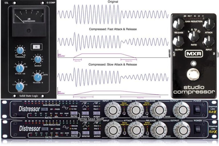
Dynamic range compression is easily one of the most-used essential audio effects/processes. The attack and release parameters of compressors aren’t always the first to be mentioned, yet they are critical to the compressor’s performance. In this article, we’ll discuss the attack and release time parameters of compressors to deepen our understanding of compression and how…
Replacing the voltage divider (R3 and R4) with a potentiometer and feeding the pot into a second op-amp buffer will allow us to effectively alter the Q of the circuit (by altering the “R3 and R4 resistor ratio” by way of the potentiometer). Such a circuit would resemble this:
If we were to swap the resistors of the DC voltage divider with the components of the RC HPF circuit, then R1 would become the capacitor and R2 would become the resistor.
Of course, a band-stop filter can have a high order than second-order if more reactive components are included. For example, a second-order LPF and second-order HPF could be combined in parallel to produce a fourth-order BSF.
Long pass filterflow cytometry
With standard Butterworth low-pass and high-pass filters, half of the total phase-shift will happen by the cutoff frequency. The high-pass filter would cause the output signal phase to lead that of the input while the low-pass filter would cause the output signal phase to lag that of the input.
Due to this combination design possibility, some manufacturers of EQ will simply combine a separate HPF and LPF circuit together to produce a BSF.
Graphic EQs are popular to “ring out” or “tune” a live room to reduce the likelihood of feedback. These EQs will generally find the problem frequency and then cut the frequency band by a certain amount.
Note that, in general, we'll have one op-amp per two resistor-capacitor pairs in these filter circuits to maintain proper gain-staging and buffering.
On the other hand, we could have an additional capacitor in a second-order band-stop filter and the filter could remain second-order. Remember that order is the minimum amount of reactive components required and not necessarily the exact number of reactive components (though they're often on and the same).
When explaining electricity and circuit theory, we often use “ideal circumstances”. This helps us to formulate neat equations and to better understand the topics at hand.
Remember that the typical band-stop filter is essentially a HPF and LPF built in parallel. The simplest band-stop filter, then, will be the passive second-order RC BS filter. It will look like this:
Band-stop filters are often referred to as “second-order filters”. This is because, at a minimum, they must have two reactive components (typically capacitors) in their design. That's at least one reactive component for the high-pass filter section of the BSF and at least one reactive component for the low-pass filter section of the BSF.
Before we move on to digital BSFs, let's consider a common notch-style analog circuit: the twin-T notch filter circuit. It's as follows:
When studying and practicing music production or audio engineering, you will likely come across band-stop filters. Band-stop filters are powerful tools that are used in equalization and in general audio design.
By this definition, we can think of a band-stop filter as a combination of a high-pass filter (HPF) and a low-pass filter (LPF), so long as the HPF's cutoff frequency (we'll call it fH) is higher than the LPF's cutoff frequency (fL).
While ideal filters have strict cutoffs at their cutoff/corner frequencies, typical band-stop filters will have some sort of gradual rolling-off of frequencies (above the low cutoff and below the high cutoff).
Now let's move on to the low-pass portion of the band-stop filter. We'll use much of what we learned in the high-pass filter section in order to quickly understand the LPF. Note that a few of the equations will be altered.
The notch frequency (fN) of such a circuit is the point at which maximum attenuation is achieved (ideally infinite attenuation, though real-world components and the time-varying nature of most audio signal waveforms makes this impractical). The notch frequency can be calculated with the following equation:
The cutoff frequency (fL) can be found with the same formula in order to determine the passband (which is everything below the fL).
With that primer, let's discuss active and passive band-stop filters in greater detail, starting with the simpler of the two: the passive BSF.
In the case of analog band-stop filters, these active components are typically operation amplifiers. The passive components refer to the resistors, capacitors and, in some instances, inductors.
Note that the order and Q factor are fixed because, at the notch frequency, the reactance of the two series capacitors (which cause a 180º phase-shift) becomes equal to the resistance of the two series resistors (which cause no phase-shift). Being 180º out-of-phase, the current through each brand is cancelled out.
I'll reiterate here that ideal filters do not have any transition bands. They change from passband to stopband and back to passband very sharply as we sweep across the frequency spectrum.
When we combine these LPFs and HPFs together in parallel to form a band-stop filter, we could have something resembling the following:
We've been discussing the BSF as a combination of a HPF and LPF. Now let's have deeper look at the high-pass filter components in order to better understand band-stop filters.
When it comes to modulation effects, chorus is certainly one of the most popular. This versatile audio effect can be heard on countless records and helps in making audio tracks sound larger than life. In this article, we’ll discuss the chorus modulation effect and how it’s achieved. We’ll liken it to natural acoustic chorusing and…
Band-stop/notch filters are particularly good at removing problem frequencies from an audio track. This is because they can effectively eliminate frequencies within a very narrow band.
With phase and amplitude relationships fresh in our minds, let's begin our discussion of HPFs with the following graphs (amplitude vs. frequency and phase-shift vs. frequency) of a first-order high-pass with a cutoff frequency at 1 kHz:
Digital filters benefit from improved accuracy and flexibility; improved temperature and humidity resistance, and a lower cost of manufacturing.
In analog BSFs, increasing the filter order will move us closer to the steepness of an ideal filter around the cutoff frequencies. In digital BSFs, we can code plugins to pretty much have the same effect as an ideal band-stop filter.
After having studied the basic RC high-pass and low-pass filters, we can better understand the simple analog band-stop filter.
Fox Music Production is an online resource for those interested in music production and audio. It's my goal to continue learning and teaching the art of music production.
Remember that the reactive capacitance of the capacitor increases as the frequency of the input voltage/signal decreases.
Moving onto the notch filters, we can improve upon the passive twin-T notch filter by adding a single non-inverting operational amplifier and a voltage divider. That would look something like this:
Relative amplitude is measured in decibels (dB), which express the ratio of one quantity to another on a logarithmic scale. When it comes to audio signal amplitude, a 3 dB difference will be a doubling/halving of power quantities (power and ultimately sound intensity) while a 6 dB difference will be a doubling/halving of root power quantities (voltage/current and ultimately sound pressure level).
Indeed, that is the basis of BSF design, as we'll get to later in the article. But first, let's have a deeper look at what a band-stop filter is. We'll begin by observing the ideal band-stop filter.
Though Q has a definition (it's defined at the centre frequency divided by the bandwidth/passband), this definition isn't always held true.
Problem frequencies can be defined as unnatural or natural resonances or “ringing” in a signal that sounds bad and has a negative effect on the overall mix.
Knowing what we know from the previous section on high-pass filters, let's have a look at the simplest low-pass filter design: the first-order passive RC LPF:
Analog BSFs are easier to understand as we can look at a few components and produce ideal equations. Our main focus will be on analog filters. Note that many digital BSF and equalizers are designed to emulate their analog counterparts.
The order of a typical HPF or LPF determines the roll-off rate or steepness of the roll-off (and the width of the transition band). An increase in order will steepen the roll-off.
Band-stop filters also have another important frequency known as the centre frequency (fC). Because frequency (in Hertz) is logarithmic in nature, we don't calculate the average between fL and fH. Rather, we find the center frequency with the following equation:
Whether you’re an audio technician/engineer, musician, audiophile, or simply want to learn about audio and music production, this website is for you!


 Ms.Cici
 8618319014500