
Kohärenz (Physik) • Kohärenz Wellen, Kohärentes Licht - was ist kohärent
Telescope focal length is a distance from the objective to where it focuses collimated light. That is, when the light arrives from objects far enough that the wavefront entering the objective is practically flat, and the light rays are practically parallel. In complex objectives, the effective focal length is determined from the focus separation s from the last surface and the height of marginal ray hm on it, as =sD/2hm (FIG. 8). For closer objects, the focus forms farther away from the objective.
If you need bandpass filters for a frequency other than those that we offer on this page, please let us know and we will add them to our product offerings.
Highpass filter
Radio receivers: Bandpass filters help select specific radio frequency bands for tuning to different stations or channels.
For a paraboloid, K=-1 and 2=R+2z-d2/R which, knowing that z=d2/2R for parabola, yields 2=R and = R/2, with zero spherical aberration. For K=-2 (hyperboloid), 2=R+3z-d2/(R+z), with the same magnitude of longitudinal aberration as sphere, only with marginal rays focusing longer than paraxial (over-correction). Similarly, with object at infinity, any lens with spherical surfaces generates spherical aberration (positive lens under-correction, negative over-correction). In determining the basic image properties - its location with respect to imaging element, and size (first-order optics) - system aberrations are not a significant factor and can be neglected. The simplified calculation following light passing through the central, practically aberration-free portion of the optical surface/element is called paraxial, or Gaussian approximation. ◄ 1.2. Reflection and refraction ▐ 1.3.1. Gaussian approximation ► Home | Comments
Filter Type: There are various filter designs to choose from, such as Butterworth, Chebyshev, or elliptic filters. The choice depends on your specific requirements for filter characteristics like passband ripple, stopband attenuation, and steepness of rolloff.
For spherical mirror, K=0 and 2=R+z-d2/(R-z) which, knowing that the last term closely approximates 2z, implies
Filter Order: The filter order determines how steeply the filter attenuates frequencies outside the passband. Higher-order filters provide better selectivity but may have a more complex design and require more components.
Band pass filtercalculator
FIGURE 7: Image formed by a telescope lens objective, as seen through the eyepiece. Since light is slowed down in glass, the in-phase points of the incident axial wavefront W are retarded the most in the center of the lens objective L (for simplicity, both objective and eyepiece are shown as a single lens), and the least at its edges. Properly made lens objective will re-shape flat incident wavefront W into spherical (W') after exiting the lens. That is a goal for off-axis point wavefronts (Wa) as well, although some form of deviation due to tilt-created asymmetry is usually present. In terms of rays, change in direction of straight lines orthogonal to the wavefront (rays), resulting from its new shape, is called refraction. The lens objective focal length O is the distance between its second principal point P2 and the focal point F. The eyepiece (EP), placed at a distance of its focal length E from the object image h' formed by the objective, converts diverging spherical wavefront into flat, for which the eye has preference. It also increases the apparent incidence angle (α vs. ε), making the object imaged at the retina (E) appear larger by a factor ~O/E. Use of an eyepiece allows for far more light from the object's image (all of it, if properly designed) to reach the eye, much higher magnifications, and much wider fields compared to observing image formed by the objective with eye alone.
It's important to note that designing RF filters can be complex, and it often requires simulation tools and expertise in RF engineering. Depending on your specific needs, you may choose to design a custom filter or purchase a commercially available bandpass filter that meets your frequency and bandwidth requirements at 915 MHz. Commercial filters are often available with datasheets that provide detailed specifications, making them a convenient choice for many applications.
Medical devices: They are used in medical instruments like electrocardiograms (ECGs) and electroencephalograms (EEGs) to focus on specific physiological frequency components.
Bandpass filters can come in various designs, including active filters (using active components like operational amplifiers) and passive filters (using passive components like capacitors and inductors). They can be implemented as analog circuits or digital algorithms in signal processing.
Telescope objective can be a single concave mirror; it can also consist from two or more mirrors, or lenses, or of mirror and lenses combined. It gathers light and forms images of distant objects. While the image it forms can be observed directly, the eye would only receive a small fraction of the light emerging from it (FIG. 6). It is the role of the ocular - or eyepiece - to make all the light from the image formed by the objective available to the eye and, by increasing apparent angles, add a significant magnification factor to the final image formed on the retina (FIG. 7).
Signal processing: Bandpass filters can be employed in signal analysis to isolate specific frequency components of interest.
Bandpass filters are essential tools in wireless applications because the selective filtering of specific frequency ranges is required or at least, very advantageous.
Bandwidth (BW): The bandwidth is the range of frequencies that the filter permits to pass through. It is usually specified as the difference between the upper and lower -3 dB cutoff frequencies (f1 and f2), where the signal power is reduced to half (-3 dB) of its maximum value. In other words, the bandwidth defines how wide the passband is.
Band pass filterPDF
These are just a few examples of the frequency bands where bandpass filters are used in wireless applications. The choice of the appropriate frequency band and filter design depends on the specific requirements of the wireless system and the standards it needs to adhere to.
FIGURE 8: Effective focal length of a telescope system with widely separated surfaces is obtained by extending the final converging axial cone (after the last surface) backward to the point of intersection with the height of the aperture. It can be either shorter (A) or longer (B) than the physical separation between the first surface and focus. The light convergence produced at the last surface bends the chief ray (green) to produce the final system magnification M2, proportional to its effective focal length, not the surface-to-focus separation. A line connecting M2 with the effective (virtual) aperture center (dotted blue) forms an angle with the axis that is equal to the angle of incident light α. Linear size of the Airy disc is determined by the final angle of convergence (i.e. by the effective focal ratio), while its angular size (linear size divided with the effective focal length) remains that corresponding to the aperture diameter (i.e. 2.44λF/=2.44λ/D, in radians).
It's important to note that designing RF filters can be complex, and it often requires simulation tools and expertise in RF engineering. Depending on your specific needs, you may choose to design a custom filter or purchase a commercially available bandpass filter that meets your frequency and bandwidth requirements at 915 MHz. Commercial filters are often available with datasheets that provide detailed specifications, making them a convenient choice for many applications.
Impedance Matching: Ensure that the filter is impedance-matched to the input and output of your system to minimize signal reflection and maximize signal transfer.
Band pass filterapplications
Filter Type: There are various filter designs to choose from, such as Butterworth, Chebyshev, or elliptic filters. The choice depends on your specific requirements for filter characteristics like passband ripple, stopband attenuation, and steepness of rolloff.
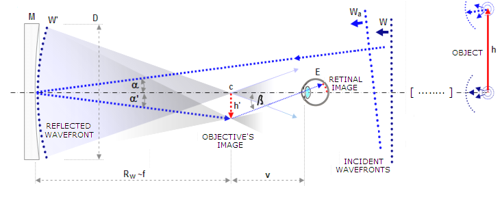
FIGURE 6: Image formed by a telescope mirror objective, as seen without the eyepiece (flat is omitted for simplicity). Wavefronts emitted from distant object of height h become practically flat over the aperture of a telescope, here a concave mirror M. The mirror changes the shape of the incoming flat wavefront section (W) into spherical (W') by delaying reflection of the points in phase belonging to the wavefront's inner area. Point of convergence (c) - or focal point - is at the center of curvature R of the wavefront. Thus, with the stop at mirror surface and exit pupil plane at mirror vertex, the mirror focal length equals the radius of the wavefront in the pupil. The top point of distant object h, at an angle α from the optical axis, is imaged into (reversed) top of the image h' by off-axis wavefront Wa, originating at the object's top point. If observed directly, from the least distance of distinct vision v (approx. 25cm, or 10 inches) most of the light from the object image h' misses the eye pupil (more so for the points farther off-axis, with no light from the image's reversed top reaching the eye); also, magnification is limited to /v, being the objective's focal length. The apparent image angle β determines objective magnification as Mo=tanβ/tanα.
Center Frequency (f0): The center frequency should be set to 915 MHz, as this is the frequency you want to pass through the filter.
In determining the basic image properties - its location with respect to imaging element, and size (first-order optics) - system aberrations are not a significant factor and can be neglected. The simplified calculation following light passing through the central, practically aberration-free portion of the optical surface/element is called paraxial, or Gaussian approximation. ◄ 1.2. Reflection and refraction ▐ 1.3.1. Gaussian approximation ► Home | Comments
Communication systems: Bandpass filters are used in modulators and demodulators to extract the carrier signal from a modulated waveform.
Bandpass filters can come in various designs, including active filters (using active components like operational amplifiers) and passive filters (using passive components like capacitors and inductors). They can be implemented as analog circuits or digital algorithms in signal processing.
These are just a few examples of the frequency bands where bandpass filters are used in wireless applications. The choice of the appropriate frequency band and filter design depends on the specific requirements of the wireless system and the standards it needs to adhere to.
Band pass filtercircuit
In the context of wireless RF (Radio Frequency) applications, the term "bandpass filters" is more commonly used than "band pass filters."
Band pass filterformula
Topology: Select the appropriate filter topology based on your requirements and the available components. Common topologies for RF filters include LC (inductor-capacitor), SAW (Surface Acoustic Wave), and ceramic filter.
Medical devices: They are used in medical instruments like electrocardiograms (ECGs) and electroencephalograms (EEGs) to focus on specific physiological frequency components.
Second orderband pass filter
Bandwidth (BW): The bandwidth is the range of frequencies that the filter permits to pass through. It is usually specified as the difference between the upper and lower -3 dB cutoff frequencies (f1 and f2), where the signal power is reduced to half (-3 dB) of its maximum value. In other words, the bandwidth defines how wide the passband is.
Thus, telescope consist from a single or or multi-element objective, and an eyepiece centered around the optical axis of the objective. The objective forms the focal point - a point of ray convergence on its optical axis (in terms of physical optics, the point of the highest generated wave energy, but the two generally coincide only in aberration-free system) - which determines the focal length of a telescope.
Impedance Matching: Ensure that the filter is impedance-matched to the input and output of your system to minimize signal reflection and maximize signal transfer.
Radio receivers: Bandpass filters help select specific radio frequency bands for tuning to different stations or channels.
A band pass filter is a device for wireless signal processing that is designed to allow a specific range of frequencies to pass through while attenuating or blocking frequencies outside of that range. It effectively filters out unwanted frequencies and only permits signals within a specified frequency band to be transmitted or received.
(2) eyepiece, a sophisticated magnifying glass that enables the eye to greatly enlarge projection of this image onto the retina.
2=R+(1-K)z-d2/[R-(1+K)z)] For spherical mirror, K=0 and 2=R+z-d2/(R-z) which, knowing that the last term closely approximates 2z, implies
Bandwidth (BW): The bandwidth of the filter will depend on your specific application. For ISM applications like LoRa, Sigfox, or other narrowband systems, the bandwidth may be relatively narrow, such as a few MHz or even less. For Wi-Fi or other broadband applications, the bandwidth may be wider, up to several hundred MHz.
Bandpass filters are essential tools in wireless applications because the selective filtering of specific frequency ranges is required or at least, very advantageous.
For K=-2 (hyperboloid), 2=R+3z-d2/(R+z), with the same magnitude of longitudinal aberration as sphere, only with marginal rays focusing longer than paraxial (over-correction). Similarly, with object at infinity, any lens with spherical surfaces generates spherical aberration (positive lens under-correction, negative over-correction). In determining the basic image properties - its location with respect to imaging element, and size (first-order optics) - system aberrations are not a significant factor and can be neglected. The simplified calculation following light passing through the central, practically aberration-free portion of the optical surface/element is called paraxial, or Gaussian approximation. ◄ 1.2. Reflection and refraction ▐ 1.3.1. Gaussian approximation ► Home | Comments
The very basic element of a telescope is the diameter of its aperture. Given optical quality, it is the main determinant of telescope's capabilities with respect to light gathering and resolution, thus also of its limits in useful magnification. If well made, the eyepiece has no appreciable effect on the light gathering or inherent resolution of a telescope. Its main function is magnification of the real image formed by the objective. Consequently, the main optical parameters of a telescope relate to its objective. They are:
Signal processing: Bandpass filters can be employed in signal analysis to isolate specific frequency components of interest.
In the context of wireless RF (Radio Frequency) applications, the term "bandpass filters" is more commonly used than "band pass filters."
Center Frequency (f0): This is the midpoint or central frequency within the desired passband. It defines the frequency around which the filter allows maximum signal transmission.
A band pass filter is a device for wireless signal processing that is designed to allow a specific range of frequencies to pass through while attenuating or blocking frequencies outside of that range. It effectively filters out unwanted frequencies and only permits signals within a specified frequency band to be transmitted or received.
The definition of focal length implies that an optical surface, or system, will have a constant focal length only if it focuses all rays to a single point on the path of the central ray. No actual system does since, due to the presence of spherical aberration, the location of focus varies with the ray height in the telescope pupil. For a given aperture, the focal length is conventionally defined as that with respect to the focal point formed by its marginal (edge) rays. So, for a concave mirror of the vertex radius of curvature R, aperture radius d, surface sagitta z and conic constant K, the focal length is defined by: 2=R+(1-K)z-d2/[R-(1+K)z)] For spherical mirror, K=0 and 2=R+z-d2/(R-z) which, knowing that the last term closely approximates 2z, implies
Bandwidth (BW): The bandwidth of the filter will depend on your specific application. For ISM applications like LoRa, Sigfox, or other narrowband systems, the bandwidth may be relatively narrow, such as a few MHz or even less. For Wi-Fi or other broadband applications, the bandwidth may be wider, up to several hundred MHz.
Lowpass filter
Topology: Select the appropriate filter topology based on your requirements and the available components. Common topologies for RF filters include LC (inductor-capacitor), SAW (Surface Acoustic Wave), and ceramic filter.
If you need bandpass filters for a frequency other than those that we offer on this page, please let us know and we will add them to our product offerings.
Center Frequency (f0): The center frequency should be set to 915 MHz, as this is the frequency you want to pass through the filter.
Component Selection: Choose appropriate passive components (inductors, capacitors, and sometimes resistors) and active components (if using an active filter) with values that meet your design specifications.
Similarly, with object at infinity, any lens with spherical surfaces generates spherical aberration (positive lens under-correction, negative over-correction). In determining the basic image properties - its location with respect to imaging element, and size (first-order optics) - system aberrations are not a significant factor and can be neglected. The simplified calculation following light passing through the central, practically aberration-free portion of the optical surface/element is called paraxial, or Gaussian approximation. ◄ 1.2. Reflection and refraction ▐ 1.3.1. Gaussian approximation ► Home | Comments
Communication systems: Bandpass filters are used in modulators and demodulators to extract the carrier signal from a modulated waveform.
Bandpass filters are commonly used in various wireless applications to select specific frequency bands of interest while attenuating unwanted frequencies. The choice of frequency bands for bandpass filters in wireless applications depends on the particular wireless communication standard or technology being used. Here are some common frequency bands and their associated wireless applications:
Component Selection: Choose appropriate passive components (inductors, capacitors, and sometimes resistors) and active components (if using an active filter) with values that meet your design specifications.
Bandpass filters are commonly used in various wireless applications to select specific frequency bands of interest while attenuating unwanted frequencies. The choice of frequency bands for bandpass filters in wireless applications depends on the particular wireless communication standard or technology being used. Here are some common frequency bands and their associated wireless applications:
Center Frequency (f0): This is the midpoint or central frequency within the desired passband. It defines the frequency around which the filter allows maximum signal transmission.
Filter Order: The filter order determines how steeply the filter attenuates frequencies outside the passband. Higher-order filters provide better selectivity but may have a more complex design and require more components.


 Ms.Cici
 8618319014500