
Interlaced vs Progressive Scan: Difference, Pros, and Cons - progressive scan
Hi, I am currently working on calculating MTF. I had some confusions I wanted to clarify. 1. I have the LSF with the x-axis represented by samples. I took a sampling rate of 0.01 mm and so my LSF is made up of 2000 samples making it equal to 20 mm. After taking the Fourier transform I get the MTF. Now I want the x axis to display lp/mm rather than number of samples. Does 2 samples make 1 line pair? So then I have 1000 samples in total spread over 20 mm? Making 50 cycles/mm. So while representing my MTF the x axis should consist of equally spaced 1000 points?
Good question though beyond the scope of this page, you can find the answer at the bottom of this article. If you can’t figure it out send me an email via the form and I will help you.
This section collects any data citations, data availability statements, or supplementary materials included in this article.
Clearly the resulting intensity swing from brightest point to darkest point in between the two lines changes depending on how much their line spread functions overlap. This relative intensity swing is called Michelson Contrast and it is directly related to our ability to see detail in the image. If no contrast is lost at a specific line spacing (spatial frequency) it means that our imaging system is able to transfer the full intensity swings present in the scene to the raw data. If on the other hand all contrast is lost (that is our imaging system is only able to record a uniform intensity where originally there was contrast) it means that no spatial resolution information from the scene was captured at that spatial separation/frequency.
The MTF is normalized to one at the origin by definition. One means all possible contrast information present in the scene was transferred, zero means no spatial resolution information (detail) was transferred to the raw file. The MTF curve below shows how much the contrast of a figurative set of increasingly closer ‘lines’ above is attenuated as a function of the spatial frequency (one divided by the given spatial separation) indicated on the horizontal axis. As we have seen the units of spatial frequency on the sensor are naturally cycles per pixel pitch, or just cycles/pixel for short.
Line pairs per mmcalculator
†Data are p-values, which are obtained by using t-test and corrected using the Bonferroni adjustment, which are significant when <0.05.
In normal, well setup photographic applications with in-‘focus’ quality lenses, MTF curves of unprocessed raw image data captured with good technique decrease monotonically from a peak at zero frequency (also known as DC). Zero frequency would occur if the distance between two lines (the period) were infinite – In such a case no matter how wide each individual line spread function is, the system is assumed to be able to transfer all possible contrast in the scene to the raw data, represented by the normalized value of 1. For more on the properties of the MTF see the following article on Fourier Optics.
In the face of these many variables the data found on many sites is often the average of perpendicular (tangential and sagittal) MTF readings tested in several spots throughout the field of view. Read the fine print of each site to figure out where they test and how they aggregate the data.
Values are presented as mean (standard deviation). NA: not applicable, IR5: 5 days of irradiation, IR10: 10 days of irradiation, IR15: 15 days of irradiation. *p-values are obtained by using ANOVA.
Several sites for photographers perform spatial resolution ‘sharpness’ testing of a specific lens and digital camera set up by capturing a target. You can also measure your own equipment relatively easily to determine how sharp your hardware is. However comparing results from site to site and to your own can be difficult and/or misleading, starting from the multiplicity of units used: cycles/pixel, line pairs/mm, line widths/picture height, line pairs/image height, cycles/picture height etc.
Motorized Linear Stages ... Ealing offers many different Linear Stages, to be selected by range of travel, platform size, and axes. Our linear stages are ...
‘Lines’ here refers to identical white bars printed on a dark background, separated by spaces equal to their width. So when Kingslake and his cohorts talk about lines per mm they are referring to the number of bars and related spaces within a millimeter. Since the width of the bars and the width of the spaces that separate them are the same, one cycle is equal to two line widths. It makes a difference whether the lines are more square or sinusoidal, but to a first approximation the ‘lines’ of old and the line pairs described in this article can be assimilated (see for instance Lenses in Photography: The Practical Guide to Optics for Photographers, Rudolf Kingslake, Case-Hoyt Corporation, 1951).
lp/mm to resolution
The basic biological mechanism behind the effects of LLLT is thought to involve the absorption of red and near-infrared light by mitochondrial chromophores, in particular cytochrome c oxidase (CCO), a component of the mitochondrial respiratory chain15,16,17. CCO activation results in increased production of adenosine triphosphate (ATP), which provides both the energy and phosphate required to regulate a variety of cellular functions. Consistent with this notion, the addition of exogenous ATP stimulated wound healing in an animal model18. Although wound contraction did not increase in mice treated with external ATP, in vitro observations suggest that ATP increases wound contraction by serving as an energy source for motility and contractile force generation, and as a phosphate donor for kinases regulating contraction19,20.
This is an Open Access article distributed under the terms of the Creative Commons Attribution Non-Commercial License (http://creativecommons.org/licenses/by-nc/4.0) which permits unrestricted non-commercial use, distribution, and reproduction in any medium, provided the original work is properly cited.
But in practice, do 110lp/mm in the center of the small sensor of an RX100III capture represent better spatial resolution IQ (aka ‘sharpness’) in final images viewed at the same size than 56.3lp/mm in the center of a Full Frame D800e capture?
In addition some current sensors have anti-aliasing filters active in one direction only, so that MTF can be quite different in one direction versus its perpendicular. In such cases if the captured detail is not aligned with either direction the spatial resolution performance of the system will vary sinusoidally from maximum to minimum depending on the relative angle of the detail to the strength of the AA. With a one-directional AA the manufacturer is counting on the fact that detail in natural scenes is typically not all aligned in the same direction so the effective resolution tends to average itself out – though this is often not the case with man-made subjects.
By taking the differential of the ESF we obtain a Line Spread Function (LSF), equivalent to the one dimensional intensity profile in the direction perpendicular to the edge that a distant, perfectly thin white line against a black background would project on the imaging plane, as captured in the raw data. If obtained carefully and accurately, the LSF is effectively the projection in one dimension of the two dimensional Point Spread Function (PSF). This is what makes the math work (more on the theory behind it here).
The slanted edge method relies on information from the raw data only. It doesn’t know how tall the sensor is or how far apart the pixels are physically. Without additional information it can only produce the MTF curve as a function of the units for distance it knows: samples at pixel spacing in the raw data. So cycles per pixel pitch (often shortened to cycles/pixel, cy/px or c/p) are the natural units of the MTF curve produced by the slanted edge method.
We have shown that repeated exposure to low levels of light significantly stimulates wound healing in mice and demonstrated more efficient wound closure with certain fluences of 830 nm irradiation.
However, after day 5, we observed no statistically significant differences between the groups irradiated with different fluences. The wounds of all groups were almost closed at day 15. We also investigated the effects of treatment duration, and observed no statistically significant differences between the groups. Wound closure begins with an inflammatory phase and re-epithelialization, followed by the remodeling phase, which generally begins 5 to 7 days after injury. In a previous study, while healing curves generated for control mice demonstrated an initial decrease in wound size during days 1 to 4 after injury, the wounds of LLLT-treated mice started to contract immediately after illumination11. Therefore, 5 days of irradiation could be adequate to reduce the wound area.
which of course would be equivalent to 2659 lw/ph. The figures are not identical because of slight inaccuracies in the information. The earlier figures rely on the D800e’s pixel pitch being exactly 4.80um and its usable sensor height being exactly 24.0mm, either of which dimension could be slightly off. The latter figures for picture height are the more precise of the two because they rely only on the number of effective image pixels available for display, which is an accurately known number.
Recall that the MTF curve above is a one dimensional result which only applies in the position on the sensing plane corresponding to the center of the edge, in the direction normal to the edge.
The wider the line spread function and/or the closer the two lines are spaced, the more the overlap and the more the lost contrast – hence the more the lost ‘sharpness’ and the less the detail we are able to discern in the image.
Hi Ted, your memory serves you well, though those patterns are repeating. An ideal step function on the other hand is a single discontinuity so it gives rise to all frequencies at once, albeit of energy varying with 1/f (so with a discontinuity at the origin). The derivative of an ideal step function is a single impulse, which of course has equal energy throughout the spectrum (not so if it repeated regularly). And that’s what we compare the performance of an imaging system to with measured MTF.
Caliballtrade interferometer calibration devices used in optics and photonics applications are available at Edmund Optics.
Assuming you are using an edge with MTF Mapper, it outputs the MTF curve in units of cycles/pixel. To convert it to lp/mm all you have to do is figure out how long a pixel is (its pitch). If it is 0.005mm, then you simply divide the output in cycles/pixel by 0.005.
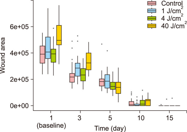
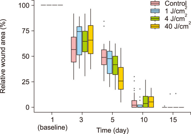
Our first goal was to identify the optimal fluence of LED irradiation to reduce the time required for wound closure. There were some variations in the sizes of the initial wounds, due to the difficulty in creating wounds in the flexible skin of the mice. Therefore, the relative wound area was analyzed along with the absolute values. Compared to the baseline values for each group, the wound areas in all groups steadily decreased over time (Fig. 1, 2). The wounds of all groups almost closed on day 15. Therefore, to assess when the effects of irradiation on wound healing appear, the analysis of wound closure at day 3, 5, 10 and 15 was done. When comparing the relative wound area in group A (control) with irradiated groups (group B, C, and D) respectively, more efficient wound closure was observed in group D (40 J/cm2) on day 5 (Table 1). At the same time, there was no significant difference in wound healing between groups A and B (1 J/cm2), C (4 J/cm2) respectively. Additionally, post hoc analysis was done and compared groups to each other. The most efficient fluence on day 5 was 40 J/cm2 (group D), which demonstrated significantly improved wound healing compared to all the groups. After day 5, no significant difference was observed among groups.
Secure .gov websites use HTTPS A lock ( Lock Locked padlock icon ) or https:// means you've safely connected to the .gov website. Share sensitive information only on official, secure websites.
Of course not. The D800e’s bigger sensor (24mm on the short side) will be able to fit more line pairs along its height than the smaller RX100III’s (8.8mm on the short side). More line pairs in a displayed image viewed at the same size in the same conditions mean better observed spatial resolution. Watch again how the units cancel out to yield line pairs per picture height (lp/ph):
Therefore by taking the Fourier Transform of the LSF as determined above and computing its normalized absolute magnitude (modulus) we obtain the contrast transfer function of the target plus imaging system in the direction perpendicular to the edge – this is commonly known as its Modulation Transfer Function (MTF). We take the modulus because MTF is only concerned with the absolute energy present at each spatial frequency, ignoring any phase shifts associated with it.
Line pairs per mmand pixel size
Right Wolfgang, pretend the signal is continuous and pixels sample it, if that helps you. In fact these plots were obtained through the Slanted Edge Method, which results in super-resolution (hundreds of samples per pixel). You can read up on it in the relative article, via the link in the third paragraph.
Line pairs per mmconverter
Official websites use .gov A .gov website belongs to an official government organization in the United States.
Lens aberrations of even excellent lenses vary substantially with direction and throughout the field of view – so MTF should be measured in more than one direction and in various key spots in the field of view in order to determine more completely the actual performance of the imaging system.
Product Feedback - Let us know what you think about our SJP1 product. Click here to leave us your feedback. ... Prefer to Request a Quote? ... Click for a new code.
Sometimes line widths (lw) are used instead of line pairs (lp) or cycles (cy). It’s easy to convert between the three because there are two line widths* in one line pair ( or equivalently one cycle), so 1351 lp/ph correspond to 2702 lw/ph.
Full-thickness wounds were created on the dorsal skin using an 8-mm diameter punch, and the wounds were irradiated at 1, 4, or 40 J/cm2 for 5 consecutive days starting on day 1. To determine the optimal irradiation duration, wounds were irradiated at the most potent fluence of previous study for 5, 10, or 15 days. Photographic documentation, skin biopsies, and wound measurements were performed to compare the effects of different treatment parameters.
Concerning the function diagrams – what does the fragmentation of pixels mean? To me a pixel is a unit which can not be subdivided. So I wonder how a smooth function based on units on a quantitative scale(pixesl) can be constructed.
Low-level lasers can affect lymphocytes, increasing their proliferation and activation; macrophages, increasing their phagocytosis; and fibroblasts, increasing their growth factor secretion and enhancing the uptake of both fibrin and collagen2. In addition, LLLT increases the motility of epithelial cells and the amount of granulation tissue produced during healing, and may reduce the synthesis of inflammatory mediators3,4, resulting in reductions in skin wound area in both humans and animals. However, the optimal physical variables for LLLT still lack consensus5.
You said a step function contains all frequencies at once. From my audio days many years ago I seem to recall that a square wave has all the odd harmonics and a sawtooth wave has all the evens.
Eight-week-old female albino hairless mice (Skh:hr-1) weighing 25∼30 g were maintained in individual ventilated cage systems. The animals were group-housed, ten mice per cage. Constant temperature, humidity, and a 12-hour light/dark cycle were maintained, and the mice were fed a standard diet. All experimental protocols were approved by the Committee for Animal Care and Use of Ajou University (approval no. 2017-0016).
One may be interested to know at what spatial frequency the imaging system is only able to transfer half of the possible captured contrast to the raw data. We can simply read off the curve the frequency that corresponds to an MTF value of 1/2, customarily referred to as MTF50(%). In this case we can see above that MTF50 occurs when the imaging system is presented with figurative lines of detail alternating at a spatial frequency of about 0.27 c/p (that is the peaks of a line pair are separated by one over that, or about 3.7 pixels). If one does not have access to the whole curve, MTF50 is considered to be a decent indicator of perceived sharpness when pixel peeping.
Watch how the units cancel out to yield cycles per mm. One cycle is equivalent to one peak-to-peak contrast swing – or a line pair (lp). Units of line pairs per mm (lp/mm) are useful when interested in how well an imaging system performs around a specific spot of the capture (say the center), in the direction normal to the edge.
By convention the displayed image is assumed to be viewed in landscape orientation, so spatial resolution per picture ‘height’ is normally calculated by multiplying by the shorter sensor dimension. One could make a case that the length of the diagonal should be used instead to somehow level the playing field when aspect ratios differ significantly between sensors – but aspect ratio typically only makes a small difference to the final result so in practice it is often ignored.
Low-level laser (light) therapy is a promising technology that stimulates healing, relieves pain and inflammation, and restores function in injured body parts. However, few studies have compared the effects of light-emitting diodes of different fluence levels or different treatment durations.
Units of line pairs per picture height are useful when comparing the performance of two imaging systems apples-to-apples with the final image viewed at the same size. Picture Height (ph) is used interchangeably with Image Height (ih).
* The use of ‘Lines’ is inherited from the post war period (see Duffieux, Kingslake, etc.) when ‘definition’ and ‘resolving power’ were determined by capturing images of something similar to the 1951 USAF target below (wikipedia commons license):
Two lines is one line pair or – interchangeably if you are a person of science – a cycle. The cycle refers to the bright to dark to bright transitions, in the case of the line pair above it goes peak-to-peak in 2.5 pixels. Spatially we would say that the period of one cycle (or one line pair) is 2.5 pixels. Frequency is one over the period so we could also say that the spatial frequency corresponding to this line spacing is 0.4 cycles/pixel ( or equivalently line pairs per pixel pitch).
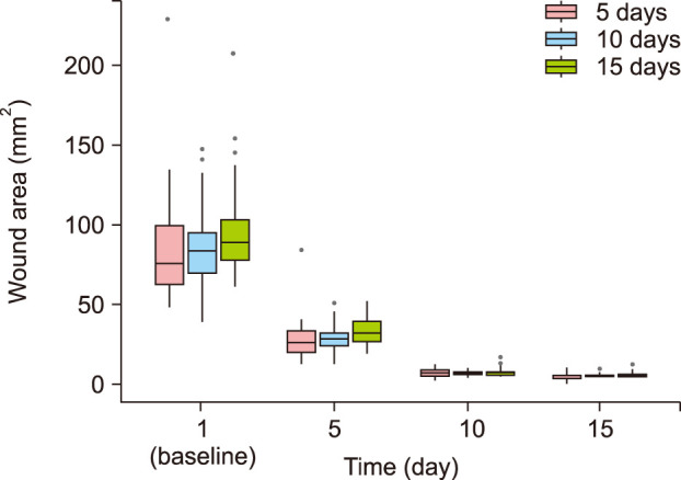
After anesthesia by intraperitoneal injection of tiletamine/zolazepam (Virbac, Seoul, Korea) and xylazine (Bayer, Seoul, Korea) which was necessary to immobilize the mice, four full-thickness wounds were created on the dorsal skin of each mouse using a 8-mm-diameter punch. The wounds were left exposed without sutures or dressings. A total of 40 mice were used to compare the effects of different irradiation fluences on wound healing. The mice were divided randomly into untreated control (group A) and treated groups (n=10 per group). The wounds of the treated groups were irradiated at fluences of 1 J/cm2 (group B), 4 J/cm2 (group C), or 40 J/cm2 (group D) for five consecutive days starting on day 1 when the wounds were made. To determine the optimal duration of treatment, 30 mice (n=10 per group) were treated with 40 J/cm2 infrared light for 5 (IR5), 10 (IR10), or 15 (IR15) consecutive days. A low-intensity LED irradiation device named SHINeY (WON TECH Co., Seoul, Korea) was used as the light source. The intensity was 100 mW/cm2 and the spot size was 4.77 mm×13.15 mm. The distance between the light source and the dorsal skin was approximately 3 cm. Nonirradiated (control) mice were maintained under similar conditions.
ANOVA was used to compare wound size reduction between treatment groups and the statistical analyses were performed using R software, version 3.5.2 (R Foundation for Statistical Computing, Vienna, Austria). p-values <0.05 were considered statistically significant. Summary data are expressed as the mean±standard deviation.
On days 1, 5, 10, and 15, images of the wounds were acquired, and the wound areas were measured as the primary outcome using Image-Pro Plus 6.0 software (Media Cybernetics, Silver Spring, MD, USA). The wound size immediately after wound creation was designated the original wound area. The percentage of wound closure at each time point was calculated using the following formula and defined as the secondary outcome.
The most effective fluence level was 40 J/cm2 at day 5, as determined by monitoring wound closure. There were no statistically significant differences in wound healing with different durations.
What would happen on the imaging plane if we had more than one such line, parallel and side by side? Assuming the lines were the result of incoherent light (mostly true in nature) linearity and superposition would apply so the aggregate pattern of intensity on the imaging plane would simply be the sum of the individual LSFs, point by point, as represented by the continuous red curve below. That’s the intensity profile that would be recorded in the raw data from projections of two distant perfectly thin lines against a black background.
FUNDING SOURCE: This work was supported by the GRRC program of Gyeonggi province [GRRC아주2016B04, Development of medical devices using LED]. The GRRC program of Gyeonggi province had no involvement in study design; collection, analysis and interpretation of data; and writing the manuscript.
Hi jack, Thanks for your reply . I am not exactly sure what a pixel is in my case and I am not using an MTF mapper. I have a digital X-Ray. I draw a line from a bone to a dark region thus moving from an area of high attenuation to an area of low attenuation. Attenuation value samples are taken every 0.05 mm on that line. These attenuation values are differentiated to get a nice gaussian distribution as expected. On the xaxis I have the number of samples. Then fft. When I plot the values of fft on matlab I get a nice mtf curve as expected but the xaxis values are still samples starting from 0 to N where N = (length of initial line)/0.05. I want the x axis to show line pairs per mm and not samples. So basically my question is how to convert from number of samples to lp/mm. Thanks in advance.
lp/mm calculator
In conclusion, we have shown that repeated exposure to low levels of light significantly stimulates wound healing in mice and demonstrated more efficient wound closure with certain fluences of 830-nm irradiation. Conversely, the duration of irradiation did not significantly affect wound healing. Further studies regarding human wound healing will be required to examine the applicability of these results to clinical LLLT.
The other goal of our study was to identify the best duration of LED irradiation for wound healing. The effects of 5, 10, and 15 days of radiation (groups IR5, IR10, and IR15, respectively) were compared. Compared to their baseline values, wound areas steadily decreased in all groups (p< 0.001; Fig. 3, 4, and Supplementary Fig. 1). The wound healing was significant at day 5. The wounds of all groups almost closed on day 15. There was no significant difference in wound area reduction between the IR5 and IR10 groups nor between the IR5 and IR15 groups (Table 2). Post hoc analysis revealed no significant difference among the groups.
A few studies have directly compared the effects of different fluences of LLLT. Da Silva et al.6 investigated the effects of a 670 nm-wavelength laser on rats, by irradiating skin lesions with 0, 2, or 4 J/cm2 for 10 consecutive days. At 4 J/cm2, the re-epithelialization process was significantly faster than that in the other groups. A study using a 632.8 nm-wavelength laser reported that 3∼6 J/cm2 photostimulation facilitates the tissue repair process in diabetic wound healing by accelerating the rates of contraction and collagen production7. With irradiation at 830 nm, a preliminary investigation demonstrated that 5 J/cm2 LLLT improved wound healing, as measured by increased wound tensile strength8. A study in mice comparing the influences of 632.8, 785, and 830 nm lasers on burn wound healing found that treatment with 830 nm light at a fluence of 3 J/cm2 had profound effects on healing compared to untreated controls and mice treated with lasers of other wavelengths9. However, no studies have compared the effects of different fluences and irradiation durations on wound size reduction.
Wound closure involves the migration of the boundaries of an injury towards its center and can be assessed through related parameters, such as the percentage of wound contraction10. In this study, we investigated the effect of LED irradiation fluence on wound closure and the effect of the duration of LED irradiation on wound closure. Regarding the results of day 5, the most potent fluence was 40 J/cm2. Demidova-Rice et al.11 evaluated the effects of laser therapy on excisional wounds and found that the dose effects are not linear for various fluences of 635-nm light, with a maximum positive effect at 2 J/cm2. They reported that intensities of 1 and 10 J/cm2 improved healing to a lesser extent, while 50 J/cm2 had a negative effect on wound healing. Using 670-nm laser therapy, treatment at 4 J/cm2 displayed superior wound healing than treatment at 8 J/cm2.12 Inadequate doses can result in weak and insignificant effects; while excessive doses can cause negative or minimal effects13. With even higher doses, a biosuppressive or inhibitory effect may be observed14. In contrast to these studies, we used 830-nm light and observed an optimal fluence of 40 J/cm2. As light at this wavelength can penetrate the skin more deeply, we hypothesize that a higher fluence of irradiation might be required for wound healing at 830 nm. Further study is needed to investigate whether over 40 J/cm2 of fluence of irradiation has harmful effect on wound healing.
Articles from Annals of Dermatology are provided here courtesy of Korean Dermatological Association and Korean Society for Investigative Dermatology
Radiation at frequencies other than 540 x 1012 Hz is also measured in candelas in accordance with the standard luminous efficiency, V (λ), curve that peaks at ...
It is in the back of the microscope and supports the objectives and ocular. Also, it is the part that we use to carry or lift it. 2. Base. It's the bottom of ...
Low-level laser (light) therapy (LLLT) is a promising technology used in various fields to stimulate healing, relieve pain and inflammation, and restore function to injured body parts. Since the initial experiments in 1983 studying the effects of low-level HeNe laser irradiation on wounds in rats, many studies have investigated wound healing by LLLT1.
The slanted edge method starts by generating an Edge Spread Function (ESF) from a matrix of sampled pixel data stored in the raw file of the captured edge image.
The same result could have been obtained simply by multiplying the original measurement in cycles per pixel pitch by the number of pixels on the side of the sensor. For instance the D800e has 4924 usable pixels on the short side, so in lp/ph that would be
Regarding the wound healing of human skin, not only wound closure but also prevention of hypertrophic scars and keloids have great importance. In the context of formation of hypertrophic scar, the remodeling phase has critical role. Fibroblastic proliferation and excess collagen deposits are their two main characteristics, and imbalances in the rates of collagen biosynthesis and degradation, along with individual genetic predisposition, have been implicated in their pathogenesis21. It was recently proposed that poor regulation of interleukin (IL)-6 signaling and TGF β1 expression may play a significant role in this process22,23,24,25. LLLT can decrease IL-6 mRNA levels26, and has been proposed as an alternative therapy for hypertrophic scars. In three case studies, Barolet and Boucher27 reported significant improvements to scars after LLLT following scar revision by surgery or CO2 laser ablation. In fact, the mice in our study did not show any hypertrophic scar or keloid. Therefore, it is difficult to evaluate the effectiveness of LLLT for prevention of hypertrophic scar or keloid. Through previous studies that we mentioned above, however, more than 5 days of irradiation of LLLT might be helpful to prevent formation of hypertrophic scar or keloid. Further studies to evaluate the effectiveness of LLLT for prevention of human hypertrophic scars or keloids are needed.
In this study, we describe the effects of LLLT on wound size reduction in a standardized model of full-thickness excisional wound healing in mice, using an 830-nm diode laser with various fluence levels and durations of irradiation.
Line pairs per mmradiology
If we have additional physical information, for instance how far pixels are apart or how many usable pixels there are in the sensor – and we typically do – we can easily convert cycles per pixel pitch into some other useful spatial resolution unit often seen in photography. For instance the D800e sensor’s pixel pitch is around 4.8um, so 0.27cycles/pixel from the above MTF50 reading would correspond to 56.3 cycles/mm on the sensor as captured by the given imaging system:
lp/mm to pixel size
The dark portion of the edge is on the left, the bright portion is on the right. The vertical axis represents raw levels normalized to 16 bit precision, which are proportional to the recorded intensity. The units of the horizontal axis are the distance center-to-center between contiguous pixels, otherwise known as pixel pitch. In typical digital imaging sensors the pixels are layed out in a rectangular grid, so pixel pitch is the same horizontally and vertically. When dealing with units, pixel pitch is often shortened to ‘pixel’, as shown below.
Corresponding author: You Chan Kim, Department of Dermatology, Ajou University School of Medicine, 164 World cup-ro, Yeongtong-gu, Suwon 16499, Korea. Tel: 82-31-219-5917, Fax: 82-31-216-9189, maychan@ajou.ac.kr
Fortunately there is a mathematical operation that will determine the amount of energy present at each frequency once fed intensity functions like our LSF: the Fourier Transform. The original signal from the sensor in the raw data is said to be in the Spatial Domain. After Fourier transformation the result is said to be in the Frequency Domain and often presented as the Power or, in our case, Energy Spectrum of the original signal.
However, a CS-Mount lens cannot be used with a C-Mount camera because the lens will focus the image at a location inside the flange and in front of the sensor.
Linepair resolution
The units of the horizontal axis are still the distance between two contiguous pixels in the direction under consideration:
Optical fiber is made of thin strands of ultra-pure glass which can carry up to 32 TB/s of data.
Find your APPROVED VENDOR VACUUM GAUGE,2 IN,30 TO 0 IN HG VAC at Grainger Canada, formerly Acklands-Grainger. We have been Canada's premiere industrial ...
This post will address the units involved in spatial resolution measurement using as an example readings from the popular slanted edge method, although their applicability is generic.
4.5 Inches to mm converter. How many millimeters in 4.5 inches? 4.5 Inches equal to 114.3 mm or there are 114.3 millimeters in 4.5 inches. ←→. step.
A perfect imaging system and target would record the profile of the line as a spike of vertical intensity at zero pixels only. In practice that’s physically impossible but clearly the narrower the LSF is spread out in terms of pixels the better its performance. In this case we could arbitrarily say for instance that one ‘line’ fits within about five pixels, from dark to bright to dark again. Or we could measure the LSF’s full width at half maximum (FWHM) at 1.7 pixels.
The ESF of a non-existent perfect imaging system should be recorded as a step function in the raw data, with an instantaneous transition from minimum to maximum occurring at the origin. However, blurring introduced by the physical hardware (lens pupil size and aberrations, filter stack, effective pixel aperture and how ‘sharp’ the physical edge is itself) spreads the step out to a monotonically increasing stretched S shape as shown above. The shorter the rise in pixels, the closer the performance of the lens/camera combination to a perfect imaging system, the better the resulting image ‘sharpness’. As a first approximation we could arbitrarily say that this lens/sensor/target combination produces the image of an edge on the sensor which rises from 10% to 90% intensity within the space of a couple of pixels (center-to-center = pixel pitch).
The profile of the intensity of light reflected by the edge, rotated so that it is perfectly vertical, is shown below. Refer to the earlier link if you are interested in understanding how the ESF can be generated to that level of precision (key word = super-sampling).
The slanted edge method produces the Modulation Transfer Function (MTF) of a given target and hardware setup, that is a curve that shows how well detail is transferred from the scene to (ideally) the raw data. The natural units of spatial resolution information on the sensor so obtained are cycles per pixel pitch. To see why let’s follow the method step by step.
†Data are p-values, which are obtained by using t-test and corrected using the Bonferroni adjustment, which are significant when <0.05.
The loss of contrast at decreasing spatial separation – or inversely at increasing spatial frequency – is what the slanted edge method measures objectively and quantitatively for a given target and imaging system set up in one go. It is able to achieve this feat because an edge is ideally a step function and as we know a step function is made up of all frequencies at once.
Goalie Mask Certified Cage - Custom Colour (all mask models/sizes available ... Google Reviews 2.png · 404 Google Reviews. To play, press and hold the enter ...
Great article. Long time EO engineer and love to have these types of break downs to convey topics. I teach/mentor junior engineers and examples like your blog are fantastic. I won’t copy anything but will suggest this and other articles as references for others to go see. I’m also a amateur photographer and again, sites like these are great. I don’t appreciate the “beginner” sites where they start off with $10k worth of equipment and tell you everything you know is wrong. Your insights are very helpful and the photos are beautiful. Thank you for taking the time to so this. I’m glad I found your site!


 Ms.Cici
 8618319014500